effect of conductor surface roughness and geometry - Ferro
effect of conductor surface roughness and geometry - Ferro
effect of conductor surface roughness and geometry - Ferro

You also want an ePaper? Increase the reach of your titles
YUMPU automatically turns print PDFs into web optimized ePapers that Google loves.
EFFECT OF CONDUCTOR SURFACE ROUGHNESS AND GEOMETRY ON<br />
MICROWAVE LOSS<br />
Liang Chai, Mike Moroz, Aziz Shaikh, <strong>and</strong> Vern Stygar<br />
<strong>Ferro</strong> Electronic Materials<br />
1395 Aspen Way<br />
Vista, California 92083<br />
ABSTRACT<br />
Low Temperature Co-fired Ceramic (LTCC)<br />
technology is being used for various high<br />
frequency applications such as T/R modules for<br />
radar, bluetooth communication modules, LAN<br />
switches, <strong>and</strong> automotive radar. One <strong>of</strong> the key<br />
properties <strong>of</strong> the electronic packages for these<br />
applications is microwave loss. LTCC<br />
metallizations are typical thick film <strong>conductor</strong>s.<br />
Conventional thick film technology has<br />
relatively low resolution, poor edge definition,<br />
<strong>and</strong> rough <strong>conductor</strong> <strong>surface</strong>. There is a concern<br />
about the magnitude <strong>of</strong> microwave losses<br />
resulting from <strong>surface</strong> <strong>roughness</strong> <strong>and</strong> line<br />
<strong>geometry</strong> <strong>of</strong> the <strong>conductor</strong>. Photoimageable<br />
technology <strong>of</strong>fers fine line (such as 25 micron<br />
lines <strong>and</strong> spaces), better edge definition, <strong>and</strong><br />
smoother <strong>surface</strong>. However, the trade-<strong>of</strong>f is that<br />
photoimageable process involves several<br />
additional manufacturing steps. An<br />
underst<strong>and</strong>ing <strong>of</strong> possibilities <strong>and</strong> limitations <strong>of</strong><br />
photoimageable technique <strong>and</strong> improved<br />
conventional screen printing methods is helpful<br />
for appropriate selection <strong>of</strong> microwave circuits<br />
manufacturing methods.<br />
This paper describes <strong>effect</strong> <strong>of</strong> <strong>surface</strong><br />
<strong>roughness</strong> <strong>of</strong> <strong>conductor</strong> on microwave losses at<br />
frequencies < 25 GHz. The insertion loss <strong>of</strong> a<br />
conventional thick film silver <strong>conductor</strong> was<br />
compared to that <strong>of</strong> a photoimageable silver<br />
<strong>conductor</strong> using the ring resonator configuration<br />
<strong>and</strong> 96% alumina substrate. It is shown that, in<br />
the frequency range <strong>of</strong> 1 to 25 GHz, the insertion<br />
loss <strong>of</strong> photoimageable silver is slightly better<br />
than that <strong>of</strong> conventional screen-printed silver<br />
<strong>conductor</strong> using the ring resonator setup. The<br />
implication <strong>of</strong> this finding for LTCC is<br />
discussed. It is proposed that conventional<br />
screen-printing may be adequate for some<br />
microwave circuits that can tolerate >30 micron<br />
lines <strong>and</strong> spaces <strong>and</strong> operates below 25 GHz.<br />
May,2001<br />
INTRODUCTION<br />
Recent advancements in Low Temperature<br />
Co-fired Ceramic (LTCC) technology have made<br />
it increasingly a material <strong>of</strong> choice for high<br />
frequency packages <strong>and</strong> interconnects. The<br />
benefits <strong>of</strong> using LTCC technology include<br />
proven reliability, size reduction over st<strong>and</strong>ard<br />
hybrid circuits, superior electrical performance,<br />
ability to embed passive components, <strong>and</strong> better<br />
thermal management. Recent development <strong>of</strong><br />
silver <strong>conductor</strong> system makes it possible to<br />
further advance the technology for low cost <strong>and</strong><br />
high performance applications [1].<br />
One <strong>of</strong> the key properties <strong>of</strong> interest to the<br />
packaging designers is the total material loss.<br />
LTCC metallizations are typical thick film<br />
<strong>conductor</strong>s. Microwave loss typically comes<br />
from the following origins: ceramic, metal<br />
<strong>conductor</strong>, metal-ceramic interface, radiation,<br />
<strong>and</strong> <strong>surface</strong> <strong>roughness</strong>. There is a concern about<br />
the contribution to the microwave loss from the<br />
<strong>surface</strong> <strong>roughness</strong>. It has been well known that<br />
microwave propagates along the <strong>conductor</strong><br />
<strong>surface</strong> (skin <strong>effect</strong>) [2]. For example, the skin<br />
depth <strong>of</strong> silver <strong>conductor</strong> is about 0.64 micron at<br />
10 GHz. Therefore, <strong>surface</strong> <strong>roughness</strong> <strong>and</strong><br />
<strong>conductor</strong> trace <strong>geometry</strong> (edges) may have<br />
significant <strong>effect</strong> on the microwave loss at high<br />
frequencies. This paper reports the attenuation<br />
<strong>of</strong> ring resonators built using a conventional<br />
silver <strong>conductor</strong> <strong>and</strong> a photoimageable silver<br />
<strong>conductor</strong>.<br />
EXPERIMENTS<br />
Microwave electrical measurements were done<br />
using a ring resonator setup [3]. Ring resonators<br />
were fabricated using 96% alumina substrate (25<br />
mil thick). The ring has a diameter 1.43” in<br />
order to have a fundamental resonance frequency<br />
<strong>of</strong> 1 GHz. The width <strong>of</strong> the <strong>conductor</strong> trace was<br />
designed to meet the requirement <strong>of</strong> 50-ohm
characteristic impedance. Table 1 lists the<br />
dimensions <strong>of</strong> the ring resonator test coupon.<br />
Ring resonator parts with photoimageable silver<br />
<strong>conductor</strong> were fabricated by Hibridas. Ring<br />
resonator parts with conventional silver<br />
<strong>conductor</strong> were made at <strong>Ferro</strong> using a typical<br />
silver thick film paste for hybrid applications <strong>and</strong><br />
conventional screen-printing method. The parts<br />
were fired using a one-hour firing pr<strong>of</strong>ile with<br />
peak temperature <strong>of</strong> 850 °C <strong>and</strong> a belt furnace.<br />
After firing, the parts were then cut into size to<br />
fit the fixture for microwave testing. Ring<br />
resonator parts made from co-fired silver<br />
<strong>conductor</strong> on A6 LTCC ceramic are also<br />
included for comparison. The details <strong>of</strong> the ring<br />
resonator measurement technique have been<br />
described in the previous publication [3].<br />
Ag<br />
<strong>conductor</strong><br />
Table 1 Ring resonator dimensions<br />
Substrate 96%<br />
3309 Photo<br />
imageable<br />
96%<br />
Al2O3 Al2O3<br />
33-391<br />
A6<br />
LTCC<br />
Substrate<br />
thickness<br />
(mil)<br />
25 25 24<br />
Width-strip<br />
(mil)<br />
25 25 36<br />
Width-ring<br />
(mil)<br />
45 45 36<br />
Gap (mil) 4 2 9<br />
Roughness,<br />
Ra (µm)<br />
0.87 0.33 -<br />
RESULTS AND DISCUSSION<br />
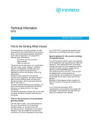
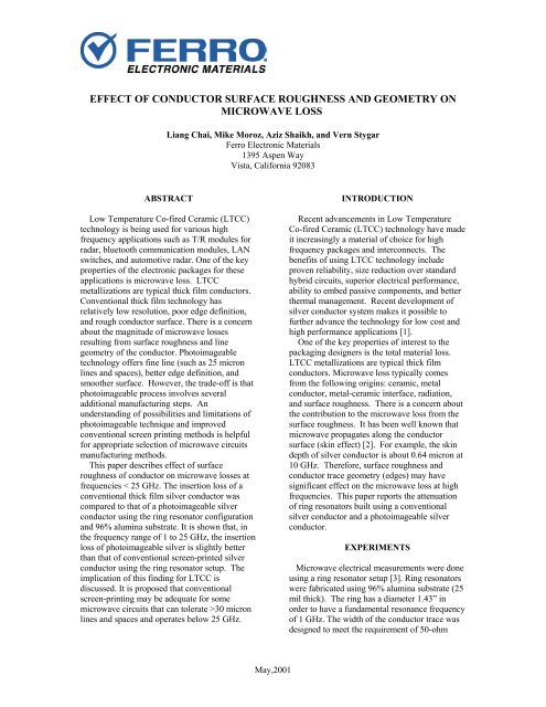
Figure 1 shows SEM photos <strong>of</strong> the gaps<br />
between strip <strong>and</strong> ring <strong>of</strong> the resonator parts. The<br />
ring resonator part built using photoimageable<br />
silver <strong>conductor</strong> shows better-defined edges <strong>and</strong><br />
vertical walls than that built using conventional<br />
screen-printed silver <strong>conductor</strong>.<br />
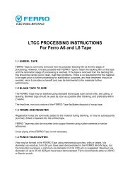
The <strong>surface</strong> <strong>of</strong> the photoimageable <strong>conductor</strong><br />
is also smoother. The <strong>surface</strong> <strong>roughness</strong> (Ra) <strong>of</strong><br />
the conventional silver <strong>conductor</strong> is 0.87, while<br />
the <strong>roughness</strong> <strong>of</strong> the photoimageable silver is<br />
0.33 (Table 1). Figure 2 shows the <strong>surface</strong><br />
pr<strong>of</strong>iles <strong>of</strong> the strip lines <strong>of</strong> the ring resonator<br />
May,2001<br />
(a)<br />
(b)<br />
Figure 1. Ring resonators made using (a)<br />
photoimageable silver, <strong>and</strong> (b) conventional<br />
silver <strong>and</strong> alumina substrate.<br />
Figure 2. Surface pr<strong>of</strong>iles <strong>of</strong> the ring resonators<br />
parts. The <strong>surface</strong> smoothness <strong>of</strong> the 96%<br />
alumina is about 0.5 microns.<br />
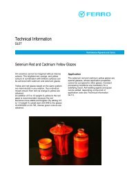
Figure 3 shows the attenuation <strong>of</strong> the ring<br />
resonators as a function <strong>of</strong> frequency. The<br />
attenuation <strong>of</strong> the photoimageable silver is<br />
slightly lower that that <strong>of</strong> conventional silver<br />
<strong>conductor</strong>. However, the microwave losses <strong>of</strong><br />
the resonator parts using photoimageable
<strong>conductor</strong> <strong>and</strong> conventional <strong>conductor</strong> seem<br />
comparable in the frequency range from 1 to 25<br />
GHz. Several factors (discussed below) may<br />
alter the results. It is also interesting that the<br />
ring resonator built using a co-fired silver<br />
<strong>conductor</strong> on A6 LTCC performs as well as the<br />
96% alumina system. Alumina normally has<br />
lower loss tangent than LTCC, <strong>and</strong> it is reflected<br />
in the overall loss. This result further<br />
demonstrates that metal contributes significantly<br />
to the total loss at the microwave frequency [4].<br />
Figure 3. Microwave properties <strong>of</strong><br />
photoimageable silver <strong>and</strong> conventional silver on<br />
96% alumina. (The attenuation <strong>of</strong> a co-fired<br />
silver <strong>conductor</strong> on A6 LTCC is also included<br />
for comparison).<br />
Several factors may contribute to the<br />
microwave losses reported here. First, the<br />
<strong>conductor</strong> compositions may be different<br />
significantly. As it is known that both silver<br />
powder morphology <strong>and</strong> silver particle size<br />
distribution affect the firing density <strong>of</strong> the<br />
<strong>conductor</strong> traces. It is also known that the<br />
inorganic adhesion additives in the <strong>conductor</strong><br />
affect the electrical performance. Second, the<br />
gap <strong>of</strong> the ring resonator using conventional<br />
silver is larger than that using photoimageable<br />
silver because the photoimageable technology<br />
normally provides better line/gap resolution. The<br />
ring resonator using photoimageable silver is<br />
‘strongly’ coupled. The <strong>effect</strong> <strong>of</strong> the strong<br />
coupling on the finally derived loss is unknown,<br />
although corrections are taken during the<br />
calculation <strong>and</strong> normally the quality factor is<br />
better for strong coupling. Further investigation<br />
is in progress to test the frequency limit at which<br />
the <strong>conductor</strong> <strong>geometry</strong> <strong>and</strong> <strong>surface</strong> smoothness<br />
May,2001<br />
becomes more significant to the microwave loss.<br />
IMPLICATIONS TO LTCC SYSTEM<br />
Microwave performance <strong>of</strong> conventional<br />
screen printed pattern seems comparable with<br />
photoimageable technology at frequencies below<br />
25 GHz for the ring resonator setup. Assuming<br />
that this is also the case in some other<br />
configurations, the improved conventional screen<br />
printing technique may be a good choice for<br />
some applications, where line resolution <strong>of</strong> >30<br />
micron can be tolerated. Figure 4 shows the dry<br />
print <strong>of</strong> conventional thick film silver <strong>conductor</strong><br />
on A6 LTCC tape using the improved screen<br />
printing technology. It is evidence that the new<br />
screen printing technology can achieve 30micron<br />
lines <strong>and</strong> spaces. The line definition <strong>of</strong><br />
the <strong>conductor</strong> traces is inferior to the<br />
photoimageable <strong>conductor</strong>. The impact <strong>of</strong> the<br />
line definition on microwave properties<br />
measured using ring resonator technique appears<br />
to be minimum below 25 GHz. It is, therefore,<br />
proposed that at frequencies below 25 GHz,<br />
conventional screen printing technique may<br />
show advantages in cost, easy <strong>of</strong> use, <strong>and</strong> final<br />
yield. Further study is in progress to investigate<br />
the <strong>effect</strong>s <strong>of</strong> line definition on microwave<br />
properties above 25 GHz <strong>and</strong> in other designs.<br />
Figure 4. 30 micron lines (dried on A6 tape)<br />
using improved conventional screen printing<br />
technique.<br />
CONCLUSIONS<br />
At the frequency range below 25 GHz, the<br />
ring resonators using conventional screen-printed
silver <strong>and</strong> photoimageable silver show good<br />
microwave performance. Combined with the<br />
fine-line printing feature, improved conventional<br />
screen-printing may be suitable for some low<br />
cost <strong>and</strong> high performance microwave packaging<br />
applications below 25 GHz.<br />
ACKNOWLEDGEMENTS<br />
We would like to thank ITS Electronics, Inc.<br />
(Toronto, Canada) for ring resonator design,<br />
Hibridas (Kaunas, Lithuania) for fabrication <strong>of</strong><br />
the ring resonator parts using photoimageable<br />
silver, Winston Tan <strong>of</strong> Pacific Trinities<br />
Corporation (Carlsbad, CA) for fine line<br />
printing, Hector Mir<strong>and</strong>a for SEM study, <strong>and</strong><br />
Richard Nguyen for assistance in the<br />
experimental work.<br />
REFERENCES<br />
[1] L. Chai, A. Shaikh, V. Stygar, “New<br />
Generation Silver Conductor System for LTCC<br />
Applications”, 2001 Wireless Symposium, San<br />
Jose, February 14, 2001.<br />
[2] D. M. Pozar, Microwave Engineering, New<br />
York, John Wiley & Sons, 1998.<br />
[3] S. Vasudenvan <strong>and</strong> A. Shaikh, “Wide B<strong>and</strong><br />
Electrical Characterization <strong>of</strong> Low Temperature<br />
Co-fired Ceramic Tape”, Proceedings <strong>of</strong> the<br />
1995 International Symposium on<br />
Microelectronics, pp. 456-463, 1995.<br />
[4] L. Chai, A. Shaikh, V. Stygar, M. Janezic, R.<br />
Geyer, C. Holloway, T. Starr, D. Paulson,<br />
“Characterization <strong>of</strong> LTCC Material Systems at<br />
Microwave Frequencies”, IMAPS Advanced<br />
Technology Workshop on Ceramic for<br />
Microwave, March 26, 2001, Denver.<br />
May,2001