SMART GROWING CELLS - FH Wedel
SMART GROWING CELLS - FH Wedel
SMART GROWING CELLS - FH Wedel

Create successful ePaper yourself
Turn your PDF publications into a flip-book with our unique Google optimized e-Paper software.
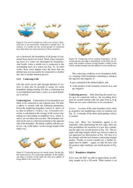
Figure 8: Cut out of a needle eye with a row of faces. Here,<br />
each face is not necessarily connected to another face. In<br />
contrast, if a needle eye has several groups of connected<br />
faces then there are some omissions of faces around it.<br />
eye is destroyed, the boundaries of all groups of connected<br />
faces need to be tested. Third, when surrounding<br />
faces of a vertex are interrupted by boundaries.<br />
And fourth, when a needle eye is connected to the<br />
surrounding faces of a vertex (see Fig. 8). In other<br />
words, these cases happen since the faces that are<br />
deleted may not necessarily be connected to a further<br />
face due to another deletion process.<br />
2.2.2 Coalescing Cells<br />
Like the mesh can be split through deletion of vertices,<br />
it must also be possible to merge two mesh<br />
boundaries during training. For that, a coalescing test<br />
is accomplished each time a vertex at a mesh boundary<br />
is moved.<br />
Coalescing test. It determines if two boundaries are<br />
likely to be connected to one coherent area. For that,<br />
a sphere is created with the following parameters.<br />
Given the neigboring boundary vertices v1 and v2 of<br />
cb, then we define c = 1/2(v1 +v2). A boundary normal<br />
nc is calculated as the average of all vectors originating<br />
at c and ending at neighbors of cb, where v1<br />
and v2 are not taken into account. The boundary normal<br />
can be seen as a direction pointing to the opposite<br />
side of the boundary. We define a sphere with the center<br />
at c+ncr with radius r as the average length of the<br />
edges at cb.<br />
Figure 9: Coalescing process at a mesh corner. On the left,<br />
the search process of a coalescing candidate. In the middle,<br />
one edge is created, on the right, the only face capable of<br />
being added is the corner face.<br />
Figure 10: Coalescing of two separate boundaries. In the<br />
second picture, the edge is determined, in the third, the triangle<br />
with smallest variance of edge lengths is added, in the<br />
fourth, another triangle must be added to avoid a needle eye.<br />
The coalescing condition at two boundaries hold,<br />
i.e., merging of the boundaries containing cb and q on<br />
the opposite side happens, if<br />
• q is contained in the defined sphere, and<br />
• scalar product of the boundary normals at cb and<br />
q is negative.<br />
Coalescing process. After detecting the neural vertex<br />
q to be connected with cb, the according faces<br />
must be created starting with one edge from cb to q.<br />
There are two cases which have to be considered.<br />
Corner. A corner of the same boundary arises when<br />
cb an q have one neighboring vertex in common (see<br />
Fig. 9). A triangle of the three participating vertices<br />
is created.<br />
Long side. Here, two boundaries appear to be<br />
separated. After determining the new edge, there are<br />
four possibilities for insertion of a new face containing<br />
the edge (see second picture in Fig. 10). The triangle<br />
with edge lengths which vary fewest is taken in<br />
our approach (see third picture in Fig. 10) since it is<br />
the triangle with the best features concerning triangle<br />
quality. Finally, to avoid a needle eye, a further triangle<br />
must be added — again, we take the face with<br />
the greatest edge similarity (see fourth picture in Fig.<br />
10).<br />
2.2.3 Roughness Adaption<br />
Up to now, the SGC are able to approximate an arbitrary<br />
sample set by a 2D mesh. What remains is an