Gas burners - Filter
Gas burners - Filter
Gas burners - Filter

Create successful ePaper yourself
Turn your PDF publications into a flip-book with our unique Google optimized e-Paper software.
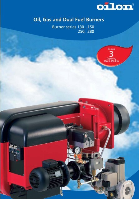
Oil, <strong>Gas</strong> and Dual Fuel Burners<br />
Burner series 130...150<br />
250, 280<br />
Group<br />
3<br />
Capacity<br />
390-3,500 kW
Table of contents<br />
General 1<br />
How to choose a burner 2<br />
Light oil <strong>burners</strong><br />
Technical data and dimensions 3-4<br />
PI-diagrams 4<br />
Capacity/back pressure graphs 5<br />
Scope of delivery 6<br />
Heavy oil <strong>burners</strong><br />
Technical data and dimensions 7-8<br />
PI-diagrams 8<br />
Capacity/back pressure graphs 9<br />
Scope of delivery 10<br />
<strong>Gas</strong> <strong>burners</strong><br />
Technical data and dimensions 11-12<br />
PI-diagrams 12<br />
Capacity/back pressure graphs 13<br />
Scope of delivery 14<br />
Dual fuel <strong>burners</strong>, light fuel oil/gas<br />
Technical data and dimensions 15-16<br />
PI-diagrams 16<br />
Capacity/back pressure graphs 17<br />
Scope of delivery 18<br />
Dual fuel <strong>burners</strong>, heavy fuel oil/gas<br />
Technical data and dimensions 19<br />
PI-diagram 20<br />
Capacity/back pressure graphs 20<br />
Scope of delivery 21<br />
<strong>Gas</strong> valve selection table 22<br />
<strong>Gas</strong> elbow 22<br />
Burner preheater 23<br />
Silencer 24<br />
Optimising combustion head pressure loss 24<br />
Low NOx gas burner 25<br />
Masonry figure 26<br />
Flame dimensions 26<br />
Servomotor 26<br />
Oil supply diagram for heavy fuel oil 27<br />
<strong>Gas</strong> pressure control assembly 27<br />
Light oil <strong>burners</strong><br />
Heavy oil <strong>burners</strong><br />
<strong>Gas</strong> <strong>burners</strong><br />
Dual fuel <strong>burners</strong>, light fuel oil/gas<br />
Dual fuel <strong>burners</strong>, heavy fuel oil/gas<br />
3 - 6<br />
7 - 10<br />
11 - 14<br />
15 - 18<br />
19 - 21
1<br />
Oil, <strong>Gas</strong> and Dual Fuel Burners<br />
Burner series 130...150<br />
250, 280<br />
Oilon oil, gas, and dual fuel <strong>burners</strong> are fully automatic, safe, and<br />
reliable. The design and manufacturing of the <strong>burners</strong> is based on<br />
economy, safety, and service as well as environmental friendliness.<br />
Our gas <strong>burners</strong> comply with the EN 676 standard, oil <strong>burners</strong><br />
with the EN 230 and EN 267 standards, and dual fuel <strong>burners</strong> with<br />
all of these standards. All <strong>burners</strong> are EU type tested. We also<br />
supply <strong>burners</strong> complying with various marine classification society<br />
requirements, such as ABS, BV, CCS, DNV, GL, KR, LR, NKK, RINA<br />
and RS.<br />
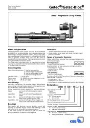
Construction<br />
All burner components are mounted directly on the burner housing.<br />
The aluminium alloy cast housing incorporates a three-phase motor<br />
that runs the fan and the oil pump. In dual fuel <strong>burners</strong>, the oil<br />
pump has its own three-phase motor. The contactors and thermal<br />
relays of the motors and the contactors of the preheater are premounted<br />
on the burner. The surface of the housing is finished<br />
with durable high-gloss paint. The housing is equipped with a<br />
hinged burner flange with a safety interlock switch, enabling the<br />
burner to be swung open to the left or right. Due to the burner<br />
flange, it is possible to service the combustion head, nozzles, and<br />
ignition electrodes without removing the burner. The stainless steel<br />
alloy combustion head and the diffuser disc can withstand<br />
temperatures up to 1,200 °C. The combustion head is adjustable,<br />
to optimise the mixing of fuel regardless of the firing rate. The<br />
burner contains a sight glass for flame observation. On the suction<br />
side of the fan there is an air damper that, together with the<br />
servomotor, automatically controls the amount of fuel and air on<br />
the basis of the firing rate required. A removable upper cover<br />
makes electrical installations and burner servicing easier.<br />
Installation and suitable applications<br />
The <strong>burners</strong> are suitable for warm and hot water boilers, steam<br />
boilers, hot air generators, and various types of process heating.<br />
They are also designed to suit furnaces with high back pressure.<br />
The <strong>burners</strong> can be mounted in horizontal, vertical and upwardfacing,<br />
or vertical and downward-facing orientation. Our <strong>burners</strong><br />
are designed for operation in covered areas, max. +50 °C. Normal<br />
operation altitude is 500 metres above sea level (other altitudes<br />
on request). The enclosure class of the burner is IP 20.<br />
Fuels<br />
Different fuels can be used depending on the burner model:<br />
KP models:<br />
- light fuel oil, viscosity 4 to 12 mm2 /s, +20 °C<br />
RP models:<br />
- heavy fuel oil, viscosity max. 250 mm2 /s, +50 °C<br />
- heavy fuel oil, viscosity max. 450 mm2 /s, +50 °C<br />
heating cartridge for pump and nozzle<br />
- heavy fuel oil, viscosity max. 650 mm2 /s, +50 °C<br />
heating cartridges as above + trace heating for the oil piping<br />
GP models:<br />
- natural gas, gases of 2nd family, groups H and E<br />
(equipment category I2R )<br />
GKP and GRP dual fuel <strong>burners</strong>:<br />
- fuel properties as above, natural gas/light fuel oil<br />
- fuel properties as above, natural gas/heavy fuel oil<br />
Burners using other fuels are available on request.<br />
Capacity regulation methods<br />
Depending on the model, options to choose from are:<br />
Two-stage, H<br />
Three-stage, T<br />
Modulating, M<br />
The two- and three-stage <strong>burners</strong> are equipped with an air damper<br />
servomotor, run time of which is 5 seconds between capacity stages.<br />
The <strong>burners</strong> automatically operate as one-, two-, or three-stage<br />
according to the load. Modulating <strong>burners</strong> are equipped with a<br />
servomotor with a transition time of 30 sec/90°. The servomotor is<br />
connected to the oil regulator and compound regulator via an axle.<br />
A modulating burner operates regardless of the firing rate, on the<br />
basis of the load. The <strong>burners</strong> are controlled on the basis of combustion<br />
gas analysis.<br />
Oilon preheater guarantees accurate oil temperature control<br />
RP and GRP models are equipped with oil shut-off valves and a filter,<br />
and with an electric mass preheater. The preheater is controlled via<br />
an electronic regulator that keeps the oil temperature stable. Stable<br />
oil temperature makes it easier to obtain optimal combustion<br />
conditions. In the heavy oil <strong>burners</strong>, the oil heated during the prepurge<br />
phase flows to the nozzle through the preheater to ensure<br />
that the oil temperature is high enough during the ignition phase.<br />
<strong>Gas</strong> equipment<br />
The gas-related components of the gas and dual fuel <strong>burners</strong> comply<br />
with the standard EN 676: two shut-off valves, pressure switches<br />
(min./max.), and an automatic valve leak tester. Other piping related<br />
equipment is available on request.<br />
Oil piping<br />
Mounted on the burner, three-stage <strong>burners</strong> with four solenoid<br />
valves (one main valve and one valve for each nozzle). Modulating<br />
<strong>burners</strong> have three solenoid valves. The oil regulator for the modulating<br />
burner is located on the oil line returning from the nozzle. The oil<br />
filter is located on the suction side of the pump. The two oil hoses<br />
enable the burner to be hinged.<br />
Flame monitoring<br />
All models are equipped with automatic flame monitoring. In KP<br />
and RP models, flame monitoring is taken care of via photocell; in<br />
GP, GKP, and GRP models, it is performed via UV cell.<br />
Control devices<br />
The control automatics (control unit) are integrated with the burner.<br />
The control unit handles all burner operation phases automatically.<br />
In the event of a burner failure, the automatics stop the burner<br />
automatically. The modulating <strong>burners</strong> also incorporate a pre-mounted<br />
capacity controller.<br />
Silencer<br />
The sound level of the <strong>burners</strong> is low, but, if desired, they can be<br />
equipped with a separate silencer to make them even quieter.<br />
Optimising combustion head pressure loss<br />
At an additional charge, the modulating <strong>burners</strong> can be equipped<br />
with a system that optimises the combustion head pressure loss.<br />
The system reduces the amount of excess air and also improves<br />
combustion figures for partial burner loads.<br />
We reserve the right to make technical alterations.
A. Procedure<br />
1. Establish relevant boiler and application information<br />
• boiler capacity and efficiency, or required burner capacity<br />
• back pressure of the furnace<br />
• fuel/fuels to be used<br />
• fuel inlet pressure to the burner<br />
• capacity regulation method of the burner<br />
2. Calculate the burner capacity. Burner capacity =<br />
boiler capacity / efficiency<br />
Example: boiler capacity of 2,500 kW, efficiency of 90 %<br />
burner capacity = 2,500 kW / 0.9 = 2,780 kW<br />
3. <strong>Gas</strong> <strong>burners</strong>: Required gas flow [m3n/h] = (burner capacity<br />
[kW] x 3.6) / gas’s calorific value [MJ/m3n]. Example: required burner capacity = 2,780 kW required<br />
gas flow = (2,780 kW x 3.6) / 35.8 MJ/m3n = 280 m3n/h, where 35.8 MJ/m3n is the calorific value of natural gas.<br />
Oil <strong>burners</strong>: Calculate the required oil flow [kg/h]. Required<br />
oil flow [kg/h] = (burner capacity [kW] x 3.6) / the oil’s calorific<br />
value [MJ/kg]. Example: required burner capacity = 2,780 kW<br />
required oil flow = (2,780 kW x 3.6) / 42.7 MJ/kg = 234 kg/h,<br />
where 42.7 MJ/kg is the calorific value of light oil.<br />
4. See the brochure for burner capacity/back pressure graphs:<br />
The graphs indicate the operating range of the burner. For<br />
example, the back pressure of a boiler with a burner capacity<br />
of 2,780 kW is 12 mbar. When you look at the point at the coordinates<br />
for 2,780 kW and 12 mbar on the graph at the bottom<br />
of the page, you can see that the point is located within the<br />
capacity/back pressure area for the GP-280 M burner. When<br />
the point representing the required back pressure and capacity<br />
is located within the indicated area, the burner capacity is a<br />
dequate. The best size of burner can be selected by choosing<br />
a burner for which the point is located as near the right-hand<br />
edge as possible. Note that different fuels and capacity regulation<br />
methods have separate graphs. The calorific value of the fuel<br />
is indicated in conjunction with the graphs.<br />
5. Choosing a valve for gas and dual fuel <strong>burners</strong>: Choose a large<br />
enough valve, using the gas valve selection table. Note that the<br />
values in the selection table apply when the furnace back pressure<br />
is 0 mbar. Therefore, you must subtract the furnace back pressure<br />
from the actual gas inlet pressure and choose the valve on the<br />
basis of the value thus obtained. The ratings shown in the table<br />
apply to natural gas.<br />
For example, when the gas inlet pressure of the burner is<br />
70 mbar, boiler back pressure is 12 mbar, and required<br />
burner capacity is 2,780 kW, the effective pressure is<br />
70 mbar - 12 mbar = 58 mbar. For the GP-280 M burner,<br />
for example, you should choose a valve allowing a minimum<br />
burner capacity of 2,780 kW with 58 mbar gas inlet<br />
pressure in this case, valve DN 65.<br />
6. Check that the outer dimensions of the burner, especially those<br />
of the combustion head, are suitable for the application; the<br />
length of the combustion head should be such that, when<br />
mounted, the combustion head is even with the furnace wall<br />
or about 10 to 20 mm inside the furnace (see ‘Masonry’ figure).<br />
7. Check the flame dimensions in the flame dimension table. Please<br />
note that the flame must not touch the walls of the furnace.<br />
8. Remember the accessories: gas pressure regulator, oil pumping<br />
unit, boiler thermostats/pressostats.<br />
How to choose a burner<br />
B. Equations and rules of thumb<br />
1. Burner capacity = boiler capacity / 0.9 (when boiler efficiency is 90 %)<br />
2. Steam boilers: 1 ton/h steam ≈ 700 kW boiler capacity<br />
3. Light oil: 1 kg/h ≈ 11.86 kW burner capacity<br />
with calorific value 42.7 MJ/kg<br />
4. Heavy oil: 1 kg/h ≈ 11.22 kW burner capacity<br />
with calorific value 40.5 MJ/kg<br />
5. Natural gas: 1 m3n/h ≈ 10 kW burner capacity<br />
with calorific value 35.84 MJ/m3n 6. The amount of combustion air:<br />
• <strong>Gas</strong> <strong>burners</strong>: required amount of combustion air for<br />
each 10 kW of burner capacity is 12 to 13 m3 /h.<br />
• Oil <strong>burners</strong>: required amount of combustion air for<br />
each kilo of oil burned [kg/h] is 13.5 m3 /h.<br />
7. Oil pumping, filtering, and preheating unit (Oilon HotBox) is<br />
required with heavy fuel oil. The required minimum pump output<br />
[kg/h] can be calculated as follows:<br />
Required minimum output [kg/h] = (oil flow to be burned in kg/h<br />
+ 150 to 200 kg/h)* 1.25 to 1.3, where the expression inside the<br />
parentheses indicates the preheated oil flow to each burner.<br />
An example of burner selection<br />
mbar (x100 Pa)<br />
20<br />
18<br />
16<br />
14<br />
12<br />
10<br />
8<br />
6<br />
4<br />
2<br />
0<br />
GP-250 M GP-280 M<br />
500 1000 1500 2000 2500 3000 3500<br />
kW<br />
Boiler pressure loss graph as<br />
a function of burner capacity<br />
The max. capacity of a hot water boiler is 2,500 kW, efficiency 0.9, and the<br />
corresponding burner capacity 2,500 kW / 0.9 = 2,780 kW. The graph indicates<br />
that a suitable gas burner for this capacity is the GP-280 M, as the pressure<br />
loss value for the boiler is located inside the area for the GP-280 M burner<br />
on the capacity/back pressure graph. The GP-250 M can also be used for this<br />
application, provided that the full boiler capacity is not required. Remember<br />
to take efficiency into account when relating the boiler pressure loss information<br />
to the burner capacity/back pressure graph.<br />
2
3<br />
620<br />
420<br />
KP-140 H/T... -150 H/T<br />
680<br />
450<br />
1030 L2<br />
R1000<br />
R1100<br />
KP-250 T, -280 T<br />
1000 L2<br />
R1020<br />
R1100<br />
45<br />
45<br />
ØD1<br />
360<br />
210<br />
ØD1<br />
420<br />
250<br />
Light oil <strong>burners</strong><br />
275<br />
365<br />
470 450<br />
275<br />
ØD4<br />
470 470<br />
365<br />
ØD4<br />
4 x M16<br />
4 x M16<br />
620<br />
420<br />
KP-130 M... -150 M<br />
1000 L2<br />
BURNER L2 B2 Ø D1 Ø D4 R1<br />
KP-140 H/T 220 470 240 255 1000<br />
KP-150 H/T 230 470 270 285 1000<br />
BURNER L2 B2 Ø D1 Ø D4 R1<br />
KP-130 M 200 430 200 215 980<br />
KP-140 M 220 470 240 255 1000<br />
KP-150 M 230 470 270 285 1000<br />
680<br />
450<br />
R1<br />
R1000<br />
50<br />
250<br />
45<br />
KP-250 M, -280 M<br />
970 L2<br />
BURNER L2 Ø D1 Ø D4<br />
KP-250 T 300 270 290<br />
KP-280 T 312 300 320<br />
BURNER L2 Ø D1 Ø D4<br />
KP-250 M 300 270 290<br />
KP-280 M 312 300 320<br />
R1020<br />
R1040<br />
50<br />
240<br />
45<br />
ØD1<br />
360<br />
415 210<br />
ØD1<br />
420<br />
430 250<br />
275<br />
365<br />
B2 450<br />
275<br />
ØD4<br />
470 470<br />
365<br />
ØD4<br />
4 x M16<br />
4 x M16
TECHNICAL DATA<br />
KP-140 H, -150 H<br />
KP-140 T, -150 T, -250 T, -280 T<br />
Light oil <strong>burners</strong><br />
BURNER KP-130 M KP-140 H KP-140 T KP-140 M KP-150 H KP-150 T KP-150 M<br />
Capacity kg/h 32 -126 47 - 200 47 - 200 47 - 200 85 - 210 56 - 240 56 - 240<br />
kW<br />
Burner motor<br />
3~ 400 V 50 Hz<br />
390 - 1500 550 - 2350 550 - 2350 550 - 2350 1000 - 2490 660 - 2850 660 - 2850<br />
Output kW 3,0 4,0 4,0 4,0 5,5 5,5 5,5<br />
Current A 6,2 8,7 8,7 8,7 11,1 11,1 11,1<br />
Speed rpm 2880 2900 2900 2900 2910 2910 2910<br />
Control unit<br />
Oil hose<br />
connection<br />
LAL1.25 LAL1.25 LAL1.25 LAL1.25 LAL1.25 LAL1.25 LAL1.25<br />
- suction R1 /2” R1 /2” R1 /2” R1 /2” R1 /2” R1 /2” R1 /2”<br />
- return R1 /2” R1 /2” R1 /2” R1 /2” R1 /2” R1 /2” R1 /2”<br />
Oil pump TA2 J7 J7 TA2 TA2 TA2 TA2<br />
Weight kg 114 107 107 118 113 113 128<br />
BURNER KP-250 T KP-250 M KP-280 T KP-280 M<br />
Capacity kg/h 55 - 270 55 - 270 76 - 295 76 - 295<br />
kW<br />
Burner motor<br />
3~ 400 V 50Hz<br />
650 - 3200 650 - 3200 900 - 3500 900 - 3500<br />
Output kW 7,5 7,5 7,5 7,5<br />
Current A 14,7 14,7 14,7 14,7<br />
Speed rpm 2855 2855 2855 2855<br />
Control unit<br />
Oil hose<br />
connection<br />
LAL1.25 LAL1.25 LAL1.25 LAL1.25<br />
- suction R3 /4” R3 /4” R3 /4” R3 /4”<br />
- return R1 /2” R1 /2” R1 /2” R1 /2”<br />
Oil pump TA2 TA3 TA2 TA3<br />
Weight kg 144 146 147 150<br />
B<br />
B<br />
A<br />
A<br />
1 2<br />
1 2<br />
1 Oil filter<br />
2 Oil pump, plugged<br />
3 Solenoid valve, NC<br />
4 Solenoid valve, NC<br />
5 Solenoid valve, NC<br />
6 Solenoid valve, NC<br />
5<br />
3 4<br />
6<br />
3 4<br />
5<br />
A Oil, inlet<br />
B Oil, return<br />
A-473M<br />
A-466T<br />
PI-diagrams<br />
1 Oil filter<br />
2 Oil pump, plugged<br />
3 Solenoid valve, NC<br />
4 Solenoid valve, NC<br />
5 Solenoid valve, NC<br />
A Oil, inlet<br />
B Oil, return<br />
KP-130 M...-150 M , -250 M, -280 M<br />
B<br />
A<br />
1<br />
2<br />
PS<br />
M<br />
1 Oil filter<br />
2 Oil pump, plugged<br />
3 Pressure gauge, gauge valve<br />
4 Solenoid valve, NC<br />
5 Solenoid valve, NC<br />
6 Pressure gauge, gauge valve<br />
7 Oil regulator/servomotor<br />
9<br />
8<br />
3<br />
7<br />
PI<br />
4<br />
6<br />
PI<br />
5<br />
8 Non-return valve<br />
9 Pressure switch, max.<br />
A Oil, inlet<br />
B Oil, return<br />
A-467T<br />
4
5<br />
Capacity/back pressure graphs<br />
mbar ( x100 Pa )<br />
mbar ( x100 Pa )<br />
mbar ( x100 Pa )<br />
mbar ( x100 Pa )<br />
20<br />
18<br />
16<br />
14<br />
12<br />
10<br />
8<br />
6<br />
4<br />
2<br />
20<br />
18<br />
16<br />
14<br />
12<br />
10<br />
8<br />
6<br />
4<br />
2<br />
20<br />
18<br />
16<br />
14<br />
12<br />
10<br />
8<br />
6<br />
4<br />
2<br />
20<br />
18<br />
16<br />
14<br />
12<br />
10<br />
8<br />
6<br />
4<br />
2<br />
KP-130 M<br />
200-152x50<br />
A-591E<br />
30 60 90 120 150<br />
kg/h<br />
180 210 240<br />
KP-140 M<br />
240-165x60<br />
30 60 90 120 150<br />
kg/h<br />
180 210 240<br />
KP-150 M<br />
A-583E<br />
270-195x75<br />
30 60 90 120 150 180 210 240<br />
kg/h<br />
KP-280 T<br />
50 100 150 200<br />
kg/h<br />
250 300 350<br />
A-576E<br />
A-450T<br />
Light oil <strong>burners</strong><br />
mbar ( x100 Pa )<br />
mbar ( x100 Pa )<br />
mbar ( x100 Pa )<br />
mbar ( x100 Pa )<br />
20<br />
18<br />
16<br />
14<br />
12<br />
10<br />
8<br />
6<br />
4<br />
2<br />
20<br />
18<br />
16<br />
14<br />
12<br />
10<br />
8<br />
6<br />
4<br />
2<br />
20<br />
18<br />
16<br />
14<br />
12<br />
10<br />
8<br />
6<br />
4<br />
2<br />
20<br />
18<br />
16<br />
14<br />
12<br />
10<br />
8<br />
6<br />
4<br />
2<br />
KP-140 H<br />
240-165x60<br />
30 60 90 120 150 180 210 240<br />
kg/h<br />
KP-150 H<br />
A-589E<br />
270-195x75<br />
30 60 90 120 150 180 210 240<br />
kg/h<br />
KP-250 T<br />
50 100 150 200 250 300 350<br />
kg/h<br />
KP-280 M<br />
50 100 150 200<br />
kg/h<br />
250 300 350<br />
A-588A<br />
A-450T<br />
A-450T<br />
mbar ( x100 Pa )<br />
mbar ( x100 Pa )<br />
mbar ( x100 Pa )<br />
20<br />
18<br />
16<br />
14<br />
12<br />
10<br />
8<br />
6<br />
4<br />
2<br />
20<br />
18<br />
16<br />
14<br />
12<br />
10<br />
8<br />
6<br />
4<br />
2<br />
20<br />
18<br />
16<br />
14<br />
12<br />
10<br />
8<br />
6<br />
4<br />
2<br />
KP-140 T<br />
240-165x60<br />
A-583E<br />
30 60 90 120 150 180 210 240<br />
kg/h<br />
KP-150 T<br />
270-195x75<br />
A-576E<br />
30 60 90 120 150 180 210 240<br />
kg/h<br />
KP-250 M<br />
50 100 150 200<br />
kg/h<br />
250 300 350<br />
Light fuel oil: 1 kg/h = 11.86 kW<br />
A-450T
Scope of delivery<br />
Burners include following equipment:<br />
Light oil <strong>burners</strong><br />
KP-140,150 H KP-140,150 T KP-130…150 M KP-250, 280 T KP- 250, 280 M<br />
Hinge flange with limit switch • • • • •<br />
Burner flange gasket • • • • •<br />
Oil nozzle/nozzles • • • • •<br />
Solenoid valves for oil • • • • •<br />
Oil pump with pressure regulating valve • • • • •<br />
Non-return valve • •<br />
2 pressure gauges for oil • •<br />
Pressure switch for return oil • •<br />
Deaerator o o<br />
2 oil hoses, length 2000 mm • • • • •<br />
Oil filter • • • • •<br />
Pressure gauge for<br />
control of inlet oil<br />
o o o o o<br />
Pressure switch for<br />
control of inlet oil<br />
o o o o o<br />
Compound regulator for regulation of<br />
air/oil ratio incl.:<br />
- oil regulator<br />
- servomotor<br />
• •<br />
Potentiometer fitted in servomotor o o o o o<br />
Differential air pressure switch o o o o o<br />
Ignition transformer • • • • •<br />
Ignition cables and electrodes • • • • •<br />
Flame sensor • • • • •<br />
Inbuilt combustion air fan with<br />
direct-driven electric motor<br />
• • • • •<br />
Air dampers • • • • •<br />
Separate servomotor<br />
for air dampers<br />
• • •<br />
Pressure gauge for<br />
fan pressure<br />
o o o o o<br />
Control unit • • • • •<br />
Capacity controller • •<br />
Motor contactors and<br />
thermal relays<br />
• • • • •<br />
Operating switches • • • • •<br />
Manual • • • • •<br />
• standard delivery<br />
o option<br />
6
7<br />
H1<br />
H2<br />
680<br />
450<br />
RP-130 H... -150 H/T<br />
1030 L2<br />
R1<br />
R1150<br />
RP-130 M... -150 M<br />
RP-250 T, -280 T RP-250 M, -280 M<br />
R1020<br />
R1090<br />
300<br />
290<br />
45<br />
45<br />
ØD1<br />
360<br />
210<br />
355<br />
ØD1<br />
420<br />
250<br />
355<br />
275<br />
365<br />
B2 450<br />
275<br />
ØD4<br />
470 470<br />
365<br />
ØD4<br />
4 x M16<br />
4 x M16<br />
H1<br />
680<br />
450<br />
H2<br />
1000 L2<br />
R1<br />
R1150<br />
50<br />
300<br />
250<br />
45<br />
970 L2<br />
R1020<br />
R1130<br />
45<br />
ØD1<br />
ØD1<br />
360<br />
415 210<br />
355<br />
BURNER L2 H1 H2 B2 Ø D1 Ø D4 R1<br />
50<br />
290<br />
240<br />
420<br />
430 250<br />
355<br />
365<br />
275<br />
B2 490<br />
RP-130 H 200 620 420 430 200 215 980<br />
RP-140 H 220 620 420 470 240 255 1000<br />
RP-150 H/T 230 750 500 470 270 285 1000<br />
BURNER L2 H1 H2 B2 Ø D1 Ø D4 R1<br />
RP-130 M 200 620 420 430 200 215 980<br />
RP-140 M 220 620 420 470 240 255 1000<br />
RP-150 M 230 750 500 470 270 285 1000<br />
1000 L2<br />
Heavy oil <strong>burners</strong><br />
BURNER L2 Ø D1 Ø D4<br />
RP-250 T 300 270 290<br />
RP-280 T 312 300 320<br />
BURNER L2 Ø D1 Ø D4<br />
RP-250 M 300 270 290<br />
RP-280 M 312 300 320<br />
275<br />
ØD4<br />
470 490<br />
365<br />
ØD4<br />
4 x M16<br />
4 x M16
TECHNICAL DATA<br />
BURNER RP-130 H RP-130 M RP-140 H RP-140 M RP-150 H RP-150 T RP-150 M<br />
Capacity kg/h 44 -121 34 - 121 60 - 180 50 - 180 86 - 210 60 - 240 60 - 240<br />
kW<br />
Burner motor<br />
3~ 400 V 50 Hz<br />
500 - 1370 390 - 1370 680 - 2040 560 - 2040 975 - 2400 680 - 2700 680 - 2700<br />
Output kW 3,0 3,0 4,0 4,0 5,5 5,5 5,5<br />
Current A 6,2 6,2 8,7 8,7 11,1 11,1 11,1<br />
Speed rpm 2880 2880 2900 2900 2910 2910 2910<br />
Control unit<br />
Oil hose<br />
connection<br />
LAL1.25 LAL1.25 LAL1.25 LAL1.25 LAL1.25 LAL1.25 LAL1.25<br />
- suction R1 /2” R1 /2” R1 /2” R1 /2” R1 /2” R1 /2” R1 /2”<br />
- return R1 /2” R1 /2” R1 /2” R1 /2” R1 /2” R1 /2” R1 /2”<br />
Oil pump<br />
Preheater<br />
3~ 400 V 50 Hz<br />
E7 TA2 E7 TA2 TA2 TA2 TA2<br />
Capacity kW 6 6 6 6 12 12 12<br />
Weight kg 115 140 121 139 150 152 167<br />
BURNER RP-250 T RP-250 M RP-280 T RP-280 M<br />
Capacity kg/h 58 - 282 58 - 282 80 - 308 80 - 308<br />
kW<br />
Burner motor<br />
3~ 400 V 50 Hz<br />
650 - 3200 650 - 3200 900 - 3500 900 - 3500<br />
Output kW 7,5 7,5 7,5 7,5<br />
Current A 14,7 14,7 14,7 14,7<br />
Speed rpm 2855 2855 2855 2855<br />
Control unit<br />
Oil hose<br />
connection<br />
LAL1.25 LAL1.25 LAL1.25 LAL1.25<br />
- suction R3 /4” R3 /4” R3 /4” R3 /4”<br />
- return R1 /2” R1 /2” R1 /2” R1 /2”<br />
Oil pump<br />
Preheater<br />
3~ 400 V 50 Hz<br />
TA2 TA3 TA2 TA3<br />
Capacity kW 12 12 12 12<br />
Weight kg 181 195 182 196<br />
RP-150 T, -250 T, -280 T<br />
B<br />
A<br />
13<br />
1 2 9 3<br />
1 Oil filter<br />
2 Oil pump, without plug<br />
3 Preheater<br />
4 Temperature regulation/<br />
lower limit<br />
5 Limit thermostat<br />
6 Pressure gauge, gauge valve<br />
7 Thermometer<br />
8 Non-return valve<br />
throttle plug ø 1.2 mm<br />
6<br />
PI<br />
TC<br />
4<br />
TS<br />
8<br />
7<br />
TZA<br />
TI<br />
5<br />
10<br />
11<br />
12<br />
9 Solenoid valve, NC<br />
10 Solenoid valve, NO<br />
11 Solenoid valve, NC<br />
12 Solenoid valve, NC<br />
13 Drilled ball valve<br />
A Oil, inlet<br />
B Oil, return<br />
Heavy oil <strong>burners</strong><br />
A-468T<br />
B<br />
A<br />
16<br />
B<br />
A<br />
12<br />
1 2 9 3<br />
PI-diagrams<br />
RP-130 H...-150 H<br />
1 Oil filter<br />
2 Oil pump, without plug<br />
3 Preheater<br />
4 Temperature regulation/<br />
lower limit<br />
5 Limit thermostat<br />
6 Pressure gauge, gauge valve<br />
7 Thermometer<br />
8 Non-return valve,<br />
throttle plug ø 1.2 mm<br />
9 Solenoid valve, NC<br />
10 Solenoid valve, NO<br />
11 Solenoid valve, NC<br />
12 Drilled ball valve<br />
A Oil, inlet<br />
B Oil, return<br />
RP-130 M...-150 M, -250 M, -280 M<br />
15<br />
1 2 15 9 3<br />
1 Oil filter<br />
2 Oil pump, with plug<br />
3 Preheater<br />
4 Temperature regulation/<br />
lower limit<br />
5 Limit thermostat<br />
6 Pressure gauge, gauge valve<br />
7 Thermometer<br />
8 Non-return valve<br />
9 Solenoid valve, NC<br />
6<br />
6<br />
PI<br />
PI<br />
14<br />
PS<br />
8<br />
TC<br />
4<br />
12<br />
TS<br />
TC TS<br />
8<br />
M<br />
TZA<br />
4<br />
7<br />
TZA<br />
7 11<br />
TI<br />
5<br />
TI<br />
5<br />
PI<br />
10<br />
10<br />
11<br />
10 Solenoid valve, NO<br />
11 Solenoid valve, NC<br />
12 Oil regulator/servomotor<br />
13 Pressure gauge, gauge valve<br />
14 Pressure switch, max.<br />
15 Deaerator<br />
16 Drilled ball valve<br />
A Oil, inlet<br />
B Oil, return<br />
13<br />
A-475M1<br />
A-469T<br />
8
9<br />
Capacity/back pressure graphs<br />
mbar ( x100 Pa )<br />
mbar ( x100 Pa )<br />
mbar ( x100 Pa )<br />
mbar ( x100 Pa )<br />
20<br />
18<br />
16<br />
14<br />
12<br />
10<br />
8<br />
6<br />
4<br />
2<br />
20<br />
18<br />
16<br />
14<br />
12<br />
10<br />
8<br />
6<br />
4<br />
2<br />
20<br />
18<br />
16<br />
14<br />
12<br />
10<br />
8<br />
6<br />
4<br />
2<br />
20<br />
18<br />
16<br />
14<br />
12<br />
10<br />
8<br />
6<br />
4<br />
2<br />
RP-130 H RP-140 H<br />
200-152x50<br />
30 60 90 120 150 180 210 240<br />
kg/h<br />
RP-130 M<br />
A-584E<br />
200-152x50<br />
30 60 90 120 150 180 210 240<br />
kg/h<br />
RP-150 M<br />
A-592E<br />
270-195x75<br />
30 60 90 120 150 180 210 240<br />
kg/h<br />
RP-280 T<br />
50 100 150 200<br />
kg/h<br />
250 300 350<br />
A-579E<br />
A-451T<br />
Heavy oil <strong>burners</strong><br />
mbar ( x100 Pa )<br />
mbar ( x100 Pa )<br />
mbar ( x100 Pa )<br />
mbar ( x100 Pa )<br />
20<br />
18<br />
16<br />
14<br />
12<br />
10<br />
8<br />
6<br />
4<br />
2<br />
20<br />
18<br />
16<br />
14<br />
12<br />
10<br />
8<br />
6<br />
4<br />
2<br />
20<br />
18<br />
16<br />
14<br />
12<br />
10<br />
8<br />
6<br />
4<br />
2<br />
20<br />
18<br />
16<br />
14<br />
12<br />
10<br />
8<br />
6<br />
4<br />
2<br />
240-165x60<br />
30 60 90 120 150 180 210 240<br />
kg/h<br />
RP-140 M<br />
A-592A<br />
240-165x60<br />
30 60 90 120 150 180 210 240<br />
kg/h<br />
RP-250 T<br />
50 100 150 200<br />
kg/h<br />
250 300 350<br />
RP-280 M<br />
50 100 150 200<br />
kg/h<br />
250 300 350<br />
A-593A<br />
A-451T<br />
A-451T<br />
mbar ( x100 Pa )<br />
mbar ( x100 Pa )<br />
mbar ( x100 Pa )<br />
20<br />
18<br />
16<br />
14<br />
12<br />
10<br />
8<br />
6<br />
4<br />
2<br />
20<br />
18<br />
16<br />
14<br />
12<br />
10<br />
8<br />
6<br />
4<br />
2<br />
20<br />
18<br />
16<br />
14<br />
12<br />
10<br />
8<br />
6<br />
4<br />
2<br />
RP-150 H<br />
270-195x75<br />
30 60 90 120 150 180 210 240<br />
kg/h<br />
RP-150 T<br />
A-594A<br />
270-195x75<br />
30 60 90 120 150 180 210 240<br />
kg/h<br />
RP-250 M<br />
50 100 150 200<br />
kg/h<br />
250 300 350<br />
A-579E<br />
A-451T<br />
Heavy fuel oil: 1 kg/h = 11.22 kW
Scope of delivery<br />
Burners include following equipment:<br />
RP-130 H...150 H RP-150 T RP-130…150 M RP-250, 280 T RP- 250, 280 M<br />
Hinge flange with limit switch • • • • •<br />
Burner flange gasket • • • • •<br />
Oil nozzle/nozzles • • • • •<br />
Heating cartridge for oil nozzle o o o o o<br />
Solenoid valves for oil • • • • •<br />
Heating cartridge for solenoid valves • • • • •<br />
Oil pump with pressure regulating valve • • • • •<br />
Heating cartridge for oil pump o o o o o<br />
Non-return valve • •<br />
2 oil pressure gauges • •<br />
Thermometer • • • • •<br />
Pressure switch for return oil • •<br />
Deaerator • •<br />
Electric preheater incl.:<br />
- limit thermostat<br />
- electronic temperature controller<br />
- temperature sensor<br />
• • • • •<br />
2 oil hoses, length 2000 mm • • • • •<br />
Electric tracing cables for burner oil pipes o o o o o<br />
Electric tracing cables for oil hoses o o o o •<br />
Oil filter • • • • •<br />
Pressure gauge for control of inlet oil o o o o o<br />
Pressure switch for control of inlet oil o o o o o<br />
Compound regulator for regulation of<br />
air/oil ratio incl.:<br />
- oil regulator<br />
- servomotor<br />
• •<br />
Potentiometer fitted in servomotor o o o o o<br />
Differential air pressure switch o o o o o<br />
Ignition transformer • • • • •<br />
Ignition cables and electrodes • • • • •<br />
Flame sensor • • • • •<br />
Inbuilt combustion air fan with<br />
direct-driven electric motor<br />
• • • • •<br />
Air dampers • • • • •<br />
Separate servomotor for air dampers • • •<br />
Pressure gauge for<br />
fan pressure<br />
o o o o o<br />
Control unit • • • • •<br />
Capacity controller • • • • •<br />
Motor contactors and thermal relays • • • • •<br />
Preheater contactors • • • • •<br />
Operating switches • • • • •<br />
Manual • • • • •<br />
• vakiotoimitus<br />
o optio<br />
Heavy oil <strong>burners</strong><br />
10
11<br />
620<br />
420<br />
GP-140 H... -150 H<br />
1000<br />
R1100<br />
1230 L2<br />
260<br />
129<br />
ØD1<br />
360<br />
210<br />
GP-250 T/M, -280 T/M<br />
275<br />
680<br />
450<br />
<strong>Gas</strong> <strong>burners</strong><br />
470 350<br />
275<br />
ØD4<br />
4 x M16<br />
620<br />
420<br />
GP-130 T... -150 T/M<br />
R1<br />
R1000<br />
1200 L2<br />
BURNER L2 Ø D1 Ø D4 R1<br />
GP-140 H 220 240 255 1000<br />
GP-150 H 230 270 285 1000<br />
R1020<br />
R1040<br />
1200 L2<br />
50<br />
455<br />
260<br />
130<br />
ØD1<br />
440<br />
430 250<br />
50<br />
465<br />
260<br />
365<br />
129<br />
ØD1<br />
360<br />
415 210<br />
470 380<br />
365<br />
ØD4<br />
4 x M16<br />
275<br />
B2 350<br />
BURNER L2 B2 Ø D1 Ø D4 R1<br />
GP-130 T/M 200 430 200 215 980<br />
GP-140 T/M 220 470 240 255 1000<br />
GP-150 T/M 230 470 270 285 1000<br />
BURNER L2 Ø D1 Ø D4<br />
GP-250 T/M 300 270 290<br />
GP-280 T/M 312 300 320<br />
275<br />
ØD4<br />
4 x M16
TECHNICAL DATA<br />
BURNER GP-130 T GP-130 M GP-140 H GP-140 T GP-140 M GP-150 H GP-150 T GP-150 M<br />
Capacity kW 390 - 1500 390 - 1500 410 - 2350 410 - 2350 410 - 2350 950 - 2700 450 - 2700 450 - 2700<br />
Burner motor<br />
<strong>Gas</strong> <strong>burners</strong><br />
3~ 400 V 50 Hz<br />
Output kW 3,0 3,0 4,0 4,0 4,0 5,5 5,5 5,5<br />
Current A 6,2 6,2 8,7 8,7 8,7 11,1 11,1 11,1<br />
Speed rpm 2880 2880 2900 2900 2900 2910 2910 2910<br />
Control unit LFL1.322 LFL1.322 LFL1.322 LFL1.322 LFL1.322 LFL1.322 LFL1.322 LFL1.322<br />
Weight kg 115 115 110 121 121 125 130 130<br />
BURNER GP-250 T GP-250 M GP-280 T GP-280 M<br />
Capacity kW<br />
Burner motor<br />
3~ 400 V 50 Hz<br />
370 - 2600 370 - 2600 500 - 3500 500 - 3500<br />
Output kW 5,5 5,5 7,5 7,5<br />
Current A 10,9 10,9 14,7 14,7<br />
Speed rpm 2855 2855 2855 2855<br />
Control unit LFL1.322 LFL1.322 LFL1.322 LFL1.322<br />
Weight kg 160 160 210 210<br />
GP-140 H, -150 H GP-130 T/M...-150 T/M,<br />
GP-250 T/M, -280 T/M<br />
C<br />
1<br />
2<br />
2.2<br />
PS<br />
2.1<br />
1 Ball valve, blow-off<br />
2 <strong>Gas</strong> valve<br />
2.1 <strong>Gas</strong> filter<br />
2.2 Pressure switch, min.<br />
2.3 <strong>Gas</strong> valve 1<br />
2.4 Pressure regulator<br />
2.5 <strong>Gas</strong> valve 2, two-stage<br />
3 Valve leak tester<br />
4 Pressure switch, max.<br />
5 Solenoid valve, NC, ignition gas *)<br />
6 Differential air pressure switch<br />
*) only on request<br />
2.3 2.4<br />
3<br />
2.5<br />
5<br />
PS<br />
4<br />
6<br />
PS<br />
A-493N<br />
PI-diagrams<br />
C<br />
1<br />
2<br />
PS PS<br />
1 Ball valve, blow-off<br />
2 Pressure switch, min.<br />
3 Double solenoid valve<br />
4 Valve leak tester<br />
5 Pressure switch, max.<br />
6 Solenoid valve, NC, ignition gas *)<br />
7 <strong>Gas</strong> butterfly valve<br />
8 Differential air pressure switch<br />
4<br />
*) on 130…150 <strong>burners</strong> only on request<br />
on 250, 280 <strong>burners</strong> as standard<br />
6<br />
5<br />
7<br />
8<br />
PS<br />
3 A-470T<br />
12
13<br />
Capacity/back pressure graphs<br />
mbar ( x100 Pa )<br />
mbar ( x100 Pa )<br />
mbar ( x100 Pa )<br />
mbar ( x100 Pa )<br />
20<br />
18<br />
16<br />
14<br />
12<br />
10<br />
8<br />
6<br />
4<br />
2<br />
GP-130 T<br />
200-152x50<br />
300 600 900 1200 1500 1800 2100 2400 2700<br />
kW<br />
20<br />
18<br />
16<br />
14<br />
12<br />
10<br />
8<br />
6<br />
4<br />
2<br />
GP-140 T<br />
Natural gas: gases of 2 nd family, groups H and E<br />
(equipment category I 2R )<br />
A-597A<br />
240-165x60<br />
A-582E<br />
300 600 900 1200 1500 1800 2100 2400 2700<br />
kW<br />
20<br />
18<br />
16<br />
14<br />
12<br />
10<br />
8<br />
6<br />
4<br />
2<br />
GP-150 T<br />
270-195x75<br />
A-575E<br />
300 600 900 1200 1500 1800 2100 2400 2700<br />
kW<br />
20<br />
18<br />
16<br />
14<br />
12<br />
10<br />
8<br />
6<br />
4<br />
2<br />
GP-250 M<br />
500 1000 1500 2000 2500 3000 3500<br />
kW<br />
A-452T<br />
mbar ( x100 Pa )<br />
mbar ( x100 Pa )<br />
mbar ( x100 Pa )<br />
mbar ( x100 Pa )<br />
20<br />
18<br />
16<br />
14<br />
12<br />
10<br />
8<br />
6<br />
4<br />
2<br />
<strong>Gas</strong> <strong>burners</strong><br />
GP-130 M<br />
200-152x50<br />
A-597A<br />
300 600 900 1200 1500 1800 2100 2400 2700<br />
kW<br />
20<br />
18<br />
16<br />
14<br />
12<br />
10<br />
8<br />
6<br />
4<br />
2<br />
GP-140 M<br />
240-165x60<br />
A-582E<br />
300 600 900 1200 1500 1800 2100 2400 2700<br />
kW<br />
20<br />
18<br />
16<br />
14<br />
12<br />
10<br />
8<br />
6<br />
4<br />
2<br />
GP-150 M<br />
270-195x75<br />
A-575E<br />
300 600 900 1200 1500 1800 2100 2400 2700<br />
kW<br />
20<br />
18<br />
16<br />
14<br />
12<br />
10<br />
8<br />
6<br />
4<br />
2<br />
GP-280 T<br />
500 1000 1500 2000 2500 3000 3500<br />
kW<br />
A-452T<br />
mbar ( x100 Pa )<br />
mbar ( x100 Pa )<br />
mbar ( x100 Pa )<br />
mbar ( x100 Pa )<br />
20<br />
18<br />
16<br />
14<br />
12<br />
10<br />
8<br />
6<br />
4<br />
2<br />
GP-140 H<br />
240-165x60<br />
A-588E<br />
300 600 900 1200 1500 1800 2100 2400 2700<br />
kW<br />
20<br />
18<br />
16<br />
14<br />
12<br />
10<br />
8<br />
6<br />
4<br />
2<br />
20<br />
18<br />
16<br />
14<br />
12<br />
10<br />
8<br />
6<br />
4<br />
2<br />
20<br />
18<br />
16<br />
14<br />
12<br />
10<br />
8<br />
6<br />
4<br />
2<br />
GP-150 H<br />
GP-250 T<br />
A-452T<br />
500 1000 1500 2000 2500 3000 3500<br />
kW<br />
GP-280 M<br />
270-195x75<br />
A-452T<br />
500 1000 1500 2000 2500 3000 3500<br />
kW<br />
A-587E<br />
300 600 900 1200 1500 1800 2100 2400 2700<br />
kW
Scope of delivery<br />
Burners include following equipment:<br />
<strong>Gas</strong> <strong>burners</strong><br />
GP-140 H,150 H GP-130 T...150 T GP-130 M…150 M GP-250 T, 280 T GP-250 M, 280 M<br />
Hinge flange with limit switch • • • • •<br />
Burner flange gasket • • • • •<br />
Compound regulator for regulation • • •<br />
of air/gas ratio incl.:<br />
- servomotor •<br />
Potentiometer fitted in servomotor o o o o o<br />
<strong>Gas</strong> nozzle • • • • •<br />
Pressure gauge for measuring<br />
the pressure in gas nozzle<br />
o o o o o<br />
<strong>Gas</strong> butterfly valve • • • •<br />
Max. gas pressure switch • • • • •<br />
Differential air pressure switch • • • • •<br />
Ignition transformer • • • • •<br />
Ignition cables and electrodes • • • • •<br />
Flame sensor • • • • •<br />
Inbuilt combustion air fan with<br />
direct-driven electric motor<br />
• • • • •<br />
Air dampers • • • • •<br />
Separate servomotor for air dampers •<br />
Pressure gauge for fan<br />
pressure<br />
o o o o o<br />
Control unit • • • • •<br />
Capacity controller • •<br />
Motor contactors and<br />
thermal relays<br />
• • • • •<br />
Operating switches • • • • •<br />
Elbow 90° • • • • •<br />
Double solenoid valve for gas<br />
incl.:<br />
- gas pressure switch, min.<br />
- 2 gas valves<br />
- automatic valve proving system<br />
- ball valve, blow-off (loose)<br />
• • • •<br />
<strong>Gas</strong> train<br />
incl.:<br />
- gas pressure switch, min.<br />
- main gas valve<br />
- gas valve, two-stage<br />
- pressure regulator<br />
- automatic valve proving system<br />
- filter<br />
- ball valve, blow-off (loose)<br />
•<br />
Solenoid valve for ignition gas • •<br />
Manual • • • • •<br />
• standard delivery<br />
o option<br />
14
15<br />
620<br />
420<br />
GKP-130 H... -150 H GKP-140 T, -150 T<br />
GKP-130 M... -150 M<br />
R1<br />
R1200<br />
Dual fuel <strong>burners</strong>, light fuel oil/gas<br />
1230 L2<br />
260<br />
129<br />
ØD1<br />
360<br />
210<br />
GKP-250 M, -280 M<br />
275<br />
B2 580<br />
680<br />
450<br />
275<br />
ØD4<br />
4 x M16<br />
R1020<br />
R1200<br />
620<br />
420<br />
1200 L2<br />
50<br />
455<br />
260<br />
129<br />
R1<br />
R1200<br />
1200 L2<br />
BURNER L2 B2 Ø D1 Ø D4 R1<br />
GKP-130 H 200 430 200 215 980<br />
GKP-140 H 220 470 240 255 1000<br />
GKP-150 H 230 470 270 285 1000<br />
BURNER L2 B2 Ø D1 Ø D4 R1<br />
GKP-130 M 200 430 200 215 980<br />
GKP-140 T/M 220 470 240 255 1000<br />
GKP-150 T/M 230 470 270 285 1000<br />
ØD1<br />
50<br />
440<br />
430 250<br />
465<br />
260<br />
365<br />
129<br />
ØD1<br />
360<br />
415 210<br />
470 600<br />
365<br />
ØD4<br />
275<br />
4 x M16<br />
BURNER L2 Ø D1 Ø D4<br />
GKP-250 M 300 270 290<br />
GKP-280 M 312 300 320<br />
B2 580<br />
275<br />
ØD4<br />
4 x M16
TECHNICAL DATA<br />
BURNER GKP-130 H GKP-130 M GKP-140 H GKP-140 T GKP-140 M GKP-150 H GKP-150 T GKP-150 M<br />
Capacity oil, kg/h 32 -126 32 - 126 47 - 200 47 - 200 47 - 200 85 - 210 56 - 227 56 - 227<br />
oil, kW 390 - 1500 390 - 1500 550 - 2350 550 - 2350 550 - 2350 1000 - 2490 660 - 2700 660 - 2700<br />
gas, kW<br />
Fan motor<br />
3~ 400 V 50 Hz<br />
390 - 1500 390 - 1500 550 - 2350 550 - 2350 410 - 2350 1000 - 2490 660 - 2700 450 - 2700<br />
Output kW 3,0 3,0 4,0 4,0 4,0 5,5 5,5 5,5<br />
Current A 6,2 6,2 8,7 8,7 8,7 11,1 11,1 11,1<br />
Speed rpm 2880 2880 2900 2900 2900 2910 2910 2910<br />
Control unit<br />
Oil hose<br />
connection<br />
LFL1.322 LFL1.322 LFL1.322 LFL1.322 LFL1.322 LFL1.322 LFL1.322 LFL1.322<br />
- suction R1 /2” R1 /2” R1 /2” R1 /2” R1 /2” R1 /2” R1 /2” R1 /2”<br />
- return R1 /2” R1 /2” R1 /2” R1 /2” R1 /2” R1 /2” R1 /2” R1 /2”<br />
Oil pump<br />
- Motor<br />
3~ 400 V 50 Hz<br />
J7 TA2 J7 J7 TA2 TA2 TA2 TA2<br />
Output kW 1,5 1,5 1,5 1,5 1,5 1,5 1,5 1,5<br />
Current A 3,3 3,3 3,3 3,3 3,3 3,3 3,3 3,3<br />
Speed rpm 2870 2870 2870 2870 2870 2870 2870 2870<br />
Weight kg 121 144 129 151 162 147 153 164<br />
BURNER GKP-250 M GKP-280 M<br />
Capacity oil, kg/h 55 - 220 76 - 295<br />
oil, kW 650 - 2600 900 - 3500<br />
gas, kW<br />
Fan motor<br />
3~ 400 V 50 Hz<br />
370 - 2600 500 - 3500<br />
Output kW 5,5 7,5<br />
Current A 10,9 14,7<br />
Speed rpm 2855 2855<br />
Control unit<br />
Oil hose<br />
connection<br />
LFL1.322 LFL1.322<br />
- suction R3 /4” R3 /4”<br />
- return R1 /2” R1 /2”<br />
Oil pump<br />
- Motor<br />
3~ 400 V 50 Hz<br />
TA3 TA3<br />
Output kW 1,5 1,5<br />
Current A 3,3 3,3<br />
Speed rpm 2870 2870<br />
Weight kg 270 278<br />
GKP-140 T, -150 T<br />
1<br />
B<br />
A<br />
C<br />
8<br />
2<br />
PS<br />
1 Ball valve, blow-off<br />
2 Pressure switch, min.<br />
3 Double solenoid valve<br />
4 Valve leak tester<br />
5 Pressure switch, gas, max.<br />
6 Solenoid valve, NC,<br />
ignition gas *)<br />
7 <strong>Gas</strong> butterfly valve<br />
8 Oil filter<br />
9 Oil pump, with plug<br />
9<br />
3<br />
Dual fuel <strong>burners</strong>, light fuel oil/gas<br />
10<br />
6<br />
11<br />
12<br />
13<br />
14<br />
PS<br />
A-461N<br />
10 Solenoid valve, NC<br />
11 Solenoid valve, NC<br />
12 Solenoid valve, NC<br />
13 Solenoid valve, NC<br />
14 Differential air pressure<br />
switch<br />
A Oil, inlet<br />
B Oil, return<br />
C <strong>Gas</strong><br />
*) only on request<br />
PS<br />
7<br />
5<br />
GKP-130 H...-150 H<br />
1 Ball valve, blow-off<br />
2 <strong>Gas</strong> valve<br />
2.1 <strong>Gas</strong> filter<br />
2.2 Pressure switch, min.<br />
2.3 <strong>Gas</strong> valve 1<br />
2.4 Pressure regulator<br />
2.5 <strong>Gas</strong> valve 2, two-stage<br />
3 Valve leak tester<br />
4 Pressure switch for<br />
gas, max.<br />
5 Solenoid valve, NC,<br />
ignition gas *)<br />
6 Differential air<br />
pressure switch<br />
7 Oil filter<br />
8 Oil pump, with plug<br />
GKP-130 M...-150 M,<br />
-250 M, -280 M<br />
1 Ball valve, blow-off<br />
2 Pressure switch, min.<br />
3 Double solenoid valve<br />
4 Valve leak tester<br />
5 Pressure switch, gas, max.<br />
6 Solenoid valve, NC,<br />
ignition gas *)<br />
7 <strong>Gas</strong> butterfly valve<br />
8 Oil filter<br />
9 Oil pump, with plug<br />
10 Pressure gauge,<br />
gauge valve<br />
11 Solenoid valve, NC<br />
12 Solenoid valve, NC<br />
13 Pressure gauge,<br />
gauge valve<br />
14 Oil regulator/servomotor<br />
C<br />
B<br />
A<br />
B<br />
A<br />
8<br />
1<br />
C<br />
1<br />
7<br />
2<br />
2<br />
PI-diagrams<br />
2.2<br />
8<br />
9 Solenoid valve, NC<br />
10 Solenoid valve, NC<br />
11 Solenoid valve, NC<br />
A Oil, inlet<br />
B Oil, return<br />
C <strong>Gas</strong><br />
*) only on request<br />
2.1<br />
3<br />
13<br />
14<br />
16 15<br />
PS M<br />
PS<br />
3<br />
PS<br />
2.3 2.4<br />
4<br />
9<br />
9<br />
2.5<br />
15 Non-return valve<br />
16 Pressure switch for oil, max.<br />
17 Differential air pressure switch<br />
PI<br />
PI<br />
11<br />
A Oil, inlet<br />
B Oil, return<br />
C <strong>Gas</strong><br />
*) on 130…150 <strong>burners</strong> only on request<br />
on 250, 280 <strong>burners</strong> as standard<br />
6<br />
10<br />
11<br />
5<br />
10<br />
12<br />
PS<br />
4<br />
6<br />
PS<br />
PS<br />
A-491N<br />
17<br />
A-472T<br />
PS<br />
5<br />
7<br />
16
17<br />
Dual fuel <strong>burners</strong>, light fuel oil/gas<br />
Capacity/back pressure graphs<br />
mbar ( x100 Pa )<br />
mbar ( x100 Pa )<br />
mbar ( x100 Pa )<br />
mbar ( x100 Pa )<br />
20<br />
18<br />
16<br />
14<br />
12<br />
10<br />
8<br />
6<br />
4<br />
2<br />
GKP-130 H<br />
200-152x50<br />
A-503B<br />
300 600 900 1200 1500 1800 2100 2400 2700<br />
kW<br />
20<br />
18<br />
16<br />
14<br />
12<br />
10<br />
8<br />
6<br />
4<br />
2<br />
20<br />
18<br />
16<br />
14<br />
12<br />
10<br />
8<br />
6<br />
4<br />
2<br />
GKP-140 T<br />
300 600 900 1200 1500 1800 2100 2400 2700<br />
kW<br />
GKP-150 T<br />
240-165x60<br />
A-581E<br />
270-195x75<br />
A-577E<br />
300 600 900 1200 1500 1800 2100 2400 2700<br />
kW<br />
20<br />
18<br />
16<br />
14<br />
12<br />
10<br />
8<br />
6<br />
4<br />
2<br />
GKP-250 M<br />
A-453T<br />
500 1000 1500 2000 2500 3000 3500<br />
kW<br />
Natural gas: gases of 2 nd family, groups H and E<br />
(equipment category I 2R )<br />
Light fuel oil: 1 kg/h = 11.86 kW<br />
mbar ( x100 Pa )<br />
mbar ( x100 Pa )<br />
mbar ( x100 Pa )<br />
mbar ( x100 Pa )<br />
20<br />
18<br />
16<br />
14<br />
12<br />
10<br />
8<br />
6<br />
4<br />
2<br />
20<br />
18<br />
16<br />
14<br />
12<br />
10<br />
8<br />
6<br />
4<br />
2<br />
GKP-130 M<br />
GKP-280 M<br />
200-152x50<br />
A-453T<br />
500 1000 1500 2000 2500 3000 3500<br />
kW<br />
A-504B<br />
300 600 900 1200 1500 1800 2100 2400 2700<br />
kW<br />
20<br />
18<br />
16<br />
14<br />
12<br />
10<br />
8<br />
6<br />
4<br />
2<br />
GKP-140 M<br />
240-165x60<br />
A-580E<br />
300 600 900 1200 1500 1800 2100 2400 2700<br />
kW<br />
20<br />
18<br />
16<br />
14<br />
12<br />
10<br />
8<br />
6<br />
4<br />
2<br />
GKP-150 M<br />
270-195x75<br />
A-575E<br />
300 600 900 1200 1500 1800 2100 2400 2700<br />
kW<br />
mbar ( x100 Pa )<br />
mbar ( x100 Pa )<br />
20<br />
18<br />
16<br />
14<br />
12<br />
10<br />
8<br />
6<br />
4<br />
2<br />
GKP-140 H<br />
240-165x60<br />
A-505B<br />
300 600 900 1200 1500 1800 2100 2400 2700<br />
kW<br />
20<br />
18<br />
16<br />
14<br />
12<br />
10<br />
8<br />
6<br />
4<br />
2<br />
GKP-150 H<br />
270-195x75<br />
A-586E<br />
300 600 900 1200 1500 1800 2100 2400 2700<br />
kW
Scope of delivery<br />
Burners include following equipment:<br />
GKP-130 H...150 H GKP-140 T, -150 T GKP-130 M...150 M GKP-250 M, -280 M<br />
Hinge flange with limit switch • • • •<br />
Burner flange gasket • • • •<br />
Oil nozzle/nozzles • • • •<br />
Solenoid valves for oil<br />
Oil pump with pressure<br />
• • •<br />
regulating valve • • • •<br />
Separate motor for oil pump • • • •<br />
Non-return valve • •<br />
2 pressure gauges for oil • •<br />
Pressure switch for return oil • •<br />
Deaerator o o<br />
2 oil hoses, length 2000 mm • • • •<br />
Oil filter<br />
Pressure gauge for control<br />
• • • •<br />
of inlet oi<br />
Pressure switch for control<br />
o o o o<br />
of inlet oil o o o o<br />
Compound regulator for regulation of • • •<br />
air/gas/oil ratio incl.:<br />
- oil regulator<br />
- servomotor<br />
Potentiometer fitted in servomotor o o o o<br />
<strong>Gas</strong> nozzle • • • •<br />
Pressure gauge for measuring<br />
the pressure in gas nozzle<br />
o o o o<br />
<strong>Gas</strong> butterfly valve • • •<br />
<strong>Gas</strong> pressure switch, max. • • • •<br />
Differential air pressure switch • • • •<br />
Ignition transformer • • • •<br />
Ignition cables and electrodes • • • •<br />
Flame sensor • • • •<br />
Inbuilt combustion air fan with<br />
direct-driven electric motor<br />
• • • •<br />
Air dampers • • • •<br />
Separate servomotor for air dampers<br />
Pressure gauge for<br />
•<br />
fan pressure o o o o<br />
Capacity controller • •<br />
Motor contactors and thermal relays<br />
Preheater contactors<br />
• • • •<br />
Operating switches • • • •<br />
Elbow 90° • • • •<br />
Double solenoid valve for<br />
gas incl.:<br />
- pressure switch for gas, min.<br />
- 2 gas valves<br />
- automatic valve proving system<br />
- ball valve, blow-off (loose)<br />
• • •<br />
<strong>Gas</strong> train incl.:<br />
- gas pressure switch, min.<br />
- main gas valve<br />
- gas valve, two-stage<br />
- pressure regulator<br />
- automatic valve proving system<br />
- filter<br />
- ball valve, blow-off (loose)<br />
•<br />
Solenoid valve for ignition gas •<br />
Manual • • • •<br />
• standard delivery o option<br />
Dual fuel <strong>burners</strong>, light fuel oil/gas<br />
does not include<br />
oil regulator<br />
18
19<br />
H1<br />
H2<br />
GRP-130 M... -150 M GRP-250 M, -280 M<br />
R1<br />
R1200<br />
1200 L2<br />
50<br />
515<br />
260<br />
465<br />
490<br />
129<br />
ØD1<br />
360<br />
415 210<br />
355<br />
275<br />
B2 640<br />
275<br />
ØD4<br />
4 x M16<br />
680<br />
450<br />
R1020<br />
R1200<br />
1200 L2<br />
50<br />
500<br />
260<br />
455<br />
505<br />
130<br />
ØD1<br />
440<br />
430 250<br />
355<br />
470 670<br />
BURNER L2 L4 H1 H2 B2 Ø D1 Ø D4 R1<br />
GRP-130 M 200 450 610 420 430 200 215 980<br />
GRP-140 M 220 450 610 420 470 240 255 1000<br />
GRP-150 M 230 450 750 560 470 270 285 1000<br />
BURNER L2 Ø D1 Ø D4<br />
GRP-250 M 300 270 290<br />
GRP-280 M 312 300 320<br />
TECHNICAL DATA<br />
Dual fuel <strong>burners</strong>, heavy fuel oil/gas<br />
BURNER GRP-130 M GRP-140 M GRP-150 M<br />
Capacity oil, kg/h 34 - 132 50 - 180 60 - 240<br />
oil, kW 390 - 1500 560 - 2040 680 - 2700<br />
gas, kW<br />
Fan motor<br />
3~ 400 V 50 Hz<br />
390 - 1500 410 - 2040 450 - 2700<br />
Output kW 3,0 4,0 5,5<br />
Current A 6,2 8,7 11,1<br />
Speed rpm 2880 2900 2910<br />
Control unit<br />
Oil hose<br />
connection<br />
LFL1.322 LFL1.322 LFL1.322<br />
- suction R1 /2” R1 /2” R1 /2”<br />
- return R1 /2” R1 /2” R1 /2”<br />
Oil pump<br />
- Motor<br />
3~ 400 V 50 Hz<br />
TA2 TA2 TA2<br />
Output kW 1,5 1,5 1,5<br />
Current A 3,3 3,3 3,3<br />
Speed rpm<br />
Preheater<br />
3~ 400 V 50 Hz<br />
2870 2870 2870<br />
Capacity kW 6 6 12<br />
Weight kg 167 174 198<br />
365<br />
365<br />
ØD4<br />
4 x M16<br />
POLTIN GRP-250 M GRP-280 M<br />
Capacity oil, kg/h 58 - 230 80 - 308<br />
oil, kW 650 - 2600 900 - 3500<br />
gas, kW<br />
Fan motor<br />
3~ 400 V 50 Hz<br />
370 - 2600 500 - 3500<br />
Output kW 5,5 7,5<br />
Current A 10,9 14,7<br />
Speed rpm 2855 2855<br />
Control unit<br />
Oil hose<br />
connection<br />
LFL1.322 LFL1.322<br />
- suction R3 /4” R3 /4”<br />
- return R1 /2” R1 /2”<br />
Oil pump<br />
- Motor<br />
3~ 400 V 50 Hz<br />
TA3 TA3<br />
Output kW 1,5 1,5<br />
Current A 3,3 3,3<br />
Speed rpm<br />
Preheater<br />
3~ 400 V 50 Hz<br />
2870 2870<br />
Capacity kW 12 12<br />
Weight kg 233 238
mbar ( x100 Pa )<br />
20<br />
18<br />
16<br />
14<br />
12<br />
10<br />
8<br />
6<br />
4<br />
2<br />
B<br />
A<br />
GRP-130 M...-150 M, -250 M, -280 M<br />
24<br />
8<br />
23<br />
1<br />
C<br />
21<br />
GRP-250 M<br />
A-454T<br />
500 1000 1500 2000 2500 3000 3500<br />
kW<br />
Dual fuel <strong>burners</strong>, heavy fuel oil/gas<br />
2<br />
PS<br />
15<br />
9<br />
PS<br />
PI<br />
18<br />
3<br />
M<br />
19<br />
10<br />
20<br />
16<br />
PI<br />
TC TS<br />
13<br />
12<br />
11<br />
TZA<br />
Capacity/back pressure graphs<br />
mbar ( x100 Pa )<br />
20<br />
18<br />
16<br />
14<br />
12<br />
10<br />
8<br />
6<br />
4<br />
2<br />
GRP-130 M<br />
200-152x50<br />
A-510B<br />
300 600 900 1200 1500 1800 2100 2400 2700<br />
kW<br />
4<br />
TI<br />
mbar ( x100 Pa )<br />
mbar ( x100 Pa )<br />
14<br />
17<br />
20<br />
18<br />
16<br />
14<br />
12<br />
10<br />
8<br />
6<br />
4<br />
2<br />
20<br />
18<br />
16<br />
14<br />
12<br />
10<br />
8<br />
6<br />
4<br />
2<br />
6<br />
PI-diagram<br />
PS<br />
A-474T<br />
22<br />
PS<br />
7<br />
GRP-280 M<br />
A-454T<br />
500 1000 1500 2000 2500 3000 3500<br />
kW<br />
5<br />
GRP-140 M<br />
1 Ball valve, blow-off<br />
2 Pressure switch, min.<br />
3 Double solenoid valve<br />
4 Valve leak tester<br />
5 Pressure switch for gas, max.<br />
6 Solenoid valve, NC, ignition gas *)<br />
7 <strong>Gas</strong> butterfly valve<br />
8 Oil filter<br />
9 Oil pump, with plug<br />
10 Preheater<br />
11 Temperature regulation/lower limit<br />
12 Limit thermostat<br />
13 Pressure gauge, gauge valve<br />
14 Thermometer<br />
15 Non-return valve<br />
16 Oil regulator/servomotor<br />
17 Solenoid valve, NC<br />
18 Solenoid valve, NC<br />
19 Solenoid valve, NO<br />
20 Pressure gauge, gauge valve<br />
21 Pressure switch for oil, max.<br />
22 Differential air pressure switch<br />
23 Deaerator<br />
24 Drilled ball valve<br />
A Oil, inlet<br />
B Oil, return<br />
C <strong>Gas</strong><br />
*) only on request<br />
240-165x60<br />
A-585E<br />
300 600 900 1200 1500 1800 2100 2400 2700<br />
kW<br />
mbar ( x100 Pa )<br />
20<br />
18<br />
16<br />
14<br />
12<br />
10<br />
8<br />
6<br />
4<br />
2<br />
GRP-150 M<br />
Natural gas: gases of 2nd family, groups<br />
H and E (equipment category l2R )<br />
Heavy fuel oil: 1 kg/h = 11.22 kW<br />
270-195x75<br />
A-578E<br />
300 600 900 1200 1500 1800 2100 2400 2700<br />
kW<br />
20
21<br />
Scope of delivery<br />
Dual fuel <strong>burners</strong>, heavy fuel oil/gas<br />
Burners include following equipment:<br />
GRP-130 M...-150 M GRP-250 M, -280 M<br />
Hinge flange with limit switch • •<br />
Burner flange gasket • •<br />
Oil nozzle/nozzles • •<br />
Heating cartridge for oil nozzle o o<br />
Solenoid valves for oil • •<br />
Heating cartridge for solenoid valves • •<br />
Oil pump with pressure regulating valve • •<br />
Heating cartridge for oil pump o o<br />
Separate motor for oil pump • •<br />
Non-return valve • •<br />
2 pressure gauges for oil • •<br />
Thermometer • •<br />
Pressure switch for return oil • •<br />
Deaerator for oil • •<br />
Electric preheater incl.:<br />
- limit thermostat<br />
- electronic temperature controller<br />
- temperature sensor<br />
• •<br />
2 oil hoses, length 2000 mm • •<br />
Electric tracing cables for burner oil pipes o o<br />
Electric tracing cables for oil hoses o o<br />
Oil filter • •<br />
Pressure gauge for control of inlet oil o o<br />
Pressure switch for control of inlet oil o o<br />
Compound regulator for regulation of<br />
air/gas/oil ratio incl.:<br />
- oil regulator<br />
- servomotor<br />
• •<br />
Potentiometer fitted in servomotor o o<br />
<strong>Gas</strong> nozzle • •<br />
Pressure gauge for measuring<br />
the pressure in gas nozzle<br />
o o<br />
<strong>Gas</strong> butterfly valve • •<br />
<strong>Gas</strong> pressure switch, max. • •<br />
Differential air pressure switch • •<br />
Ignition transformer • •<br />
Ignition cables and electrodes • •<br />
Flame sensor • •<br />
Inbuilt combustion air fan with<br />
direct-driven electric motor<br />
• •<br />
Air dampers • •<br />
Pressure gauge for fan pressure o o<br />
Control unit • •<br />
Capacity controller • •<br />
Motor contactors and thermal relays • •<br />
Preheater contactors • •<br />
Operating switches • •<br />
Elbow 90°<br />
Double solenoid valve<br />
• •<br />
incl.:<br />
- gas pressure switch, min.<br />
- 2 gas valves<br />
- automatic valve proving system<br />
- ball valve, blow-off (loose)<br />
• •<br />
Solenoid valve for ignition gas •<br />
Manual • •<br />
• standard delivery o option
BURNER SERIES 130...150<br />
NOTE! If the gas inlet pressure is less than 20 mbar or if the gas used is not<br />
among those mentioned, evaluation must be made case-specifically.<br />
*) The max. capacities shown in the table are achieved when the boiler<br />
back pressure is 0.<br />
Natural gas 1 m3n/h ~ = 10 kW<br />
**) or corresponding type<br />
H<br />
<strong>Gas</strong> valve selection table<br />
BURNER GAS VALVE BURNER MAX. CAPACITY kW *) COMBUSTION<br />
GAS INLET PRESSURE<br />
SIZE TYPE **) 20 mbar 30 mbar 50 mbar 100 mbar<br />
HEAD<br />
GKP-130 H R2” MB-ZRDLE 940 1150 1480 1500 200-152x50<br />
GP/GKP/GRP-130 T/M DN 50 DMV-DLE 990 1210 1500 1500 200-152x50<br />
DN 65 DMV-D 1140 1400 1500 1500 200-152x50<br />
DN 80 DMV-D 1230 1500 1500 1500 200-152x50<br />
GP/GKP-140 H R2” MB-ZRDLE 1110 1360 1760 2350 240-165x60<br />
GP/GKP/GRP-140 T/M DN 50 DMV-DLE 1190 1460 1890 2350 240-165x60<br />
DN 65 DMV-D 1590 1950 2350 2350 240-165x60<br />
DN 80 DMV-D 1870 2290 2350 2350 240-165x60<br />
GP/GKP-150 H R2” MB-ZRDLE 1120 1370 1770 2500 270-195x75<br />
GP/GKP/GRP-150 T/M DN 50 DMV-DLE 1240 1520 1970 2700 270-195x75<br />
DN 65 DMV-D 1610 1980 2520 2700 270-195x75<br />
DN 80 DMV-D 1910 2340 2700 2700 270-195x75<br />
BURNER SERIES 250, 280<br />
GP/GKP/GRP-250 T/M DN 50 DMV-D 1200 1500 2000 2600 270-195x75<br />
DN 65 DMV-D 1800 2200 2600 2600 270-195x75<br />
DN 80 DMV-D 2300 2600 2600 2600 270-195x75<br />
DN 100 DMV-D 2600 2600 2600 2600 270-195x75<br />
GP/GKP/GRP-280 T/M DN 50 DMV-D 1300 1600 2100 3000 300-215x75<br />
DN 65 DMV-D 1900 2400 3100 3500 300-215x75<br />
DN 80 DMV-D 2700 3300 3500 3500 300-215x75<br />
DN 100 DMV-D 3200 3500 3500 3500 300-215x75<br />
DN 125 DMV-D 3500 3500 3500 3500 300-215x75<br />
Other dimensions available on special request<br />
L<br />
<strong>Gas</strong> elbow<br />
GAS ELBOW DIMENSIONS WITH DIFFERENT VALVES<br />
<strong>Gas</strong> inlet pressure (Pmax) at burner<br />
- max. 500 mbar when using DMV-D valve<br />
- max. 360 mbar when using MB valve<br />
R2” DN50 DN65 DN80 DN100 DN125<br />
H L L L L L L<br />
GP/GKP/GRP-130…150 440 435 465 505 530 580 750<br />
GP/GKP/GRP-250…280 450 - 510 560 615 665 745<br />
22
23<br />
Oilon ML mass preheater keeps the oil temperature<br />
stable even if the incoming temperature fluctuates.<br />
On account of the construction and the electronic<br />
regulator, the temperature of the oil flowing to the<br />
nozzle remains stable. The burner may, depending on<br />
the capacity and model, have one or more 6-kW heater<br />
equipped with a safety device to guard against<br />
overheating. The electronic regulator has an integrated<br />
minimum temperature limiter as well; this prevents<br />
the burner from starting if the oil is too cold.<br />
Burner preheater<br />
Accurate temperature control<br />
guarantees good combustion<br />
In burning heavy fuel oil, the right atomising viscosity of the<br />
oil is essential for good combustion and low combustion gas<br />
emissions. A prerequisite for stable atomising viscosity is that<br />
the oil temperature stays stable throughout the firing rate.<br />
Control based<br />
on Oilon technology<br />
Control based<br />
on traditional technology<br />
. . . . . .
Construction<br />
The MV 1 silencer is made of steel plate lined with fireproof<br />
dampening wool. The silencer is connected to the burner’s<br />
suction side via a screw connection. The silencer reduces the<br />
high-pitched sound produced by the air flow.<br />
Silencer<br />
Intake silencer, type MV 1 Silencer, type MV 3<br />
Construction<br />
The MV 3 silencer is made of steel plate lined with fireproof<br />
dampening wool. This wheel-equipped silencer isolates the<br />
burner from four sides. The MV 3 silencer reduces the sounds<br />
produced when the burner operates.<br />
Optimising combustion head pressure loss<br />
The speed of the combustion air at the combustion head is<br />
controlled by moving the adjustment ring in the axial direction.<br />
When the adjustment ring is in the front position, the gap<br />
between the ring and the diffuser disc is small and therefore<br />
suitable for the minimum burner capacity. When the adjustment<br />
ring is in the rear position, the gap between the ring and the<br />
diffuser disc is large and therefore suitable for maximum capacity.<br />
Automatic combustion head optimisation is available as an<br />
option for the modulating <strong>burners</strong>. With this, the movable<br />
combustion head adjustment ring is connected to the<br />
servomotor regulating the burner capacity. This way, the<br />
adjustment ring is always optimised for the required capacity.<br />
Furthermore, the adjustment range of the burner increases.<br />
24
25<br />
Low NOx technology for lower<br />
combustion gas emissions<br />
The development of the Low NOx <strong>burners</strong> increased the Oilon<br />
burner selection considerably. The greatest improvement<br />
took place at the burner combustion head, where changes<br />
to the flow of the combustion gases enable lower NOx<br />
emissions. Various tests and practical experience prove that<br />
the Low NOx <strong>burners</strong> can achieve 40 to 60 % lower emission<br />
levels than traditional <strong>burners</strong> do. The carbon monoxide<br />
emissions of the Low NOx <strong>burners</strong> are also very low.<br />
The high efficiency typical of Oilon <strong>burners</strong> applies to the<br />
Low NOx <strong>burners</strong>, too. With respect to the setting dimensions,<br />
the outer dimensions of the burner combustion head are the<br />
same as those of standard <strong>burners</strong>, so Low NOx <strong>burners</strong> are<br />
easy to install in place of traditional Oilon <strong>burners</strong>, without<br />
even electrical modifications. The <strong>burners</strong> are designed for<br />
gases of 2 nd family, groups H and E.
x1000mm<br />
2<br />
1<br />
3<br />
4<br />
7<br />
6<br />
5<br />
4<br />
3<br />
2<br />
1<br />
L2<br />
Masonry figure<br />
60...90°<br />
ØD1<br />
ØD2<br />
1 <strong>Gas</strong>ket<br />
2 Mounting panel<br />
3 Ceramic wool or equivalent<br />
4 Masonry<br />
ØD1 see burner dimension diagram<br />
ØD2 D1+40 mm<br />
L2 see burner dimension diagram<br />
Flame dimensions Servomotor<br />
kW<br />
Flame length<br />
max.<br />
Flame length<br />
min.<br />
Flame diameter<br />
max.<br />
Flame diameter<br />
min.<br />
0<br />
1 2 3 4 5 6 7 8 9 10 11 12 13 14 15<br />
x1000kW<br />
The dimensions apply for light oil and gas. For heavy oil, the<br />
dimensions used must be larger.<br />
The new, advanced servomotor of the modulating <strong>burners</strong><br />
makes it possible to determine the minimum capacity<br />
of the burner more quickly than before.<br />
26
27<br />
Example<br />
Drilled ball valve<br />
Drilled ball valve<br />
Example<br />
Oil supply diagram for heavy fuel oil<br />
Pressure regulating valve<br />
<strong>Gas</strong> pressure control assembly<br />
RP-...M<br />
RP-...H
Oilon invests in product development<br />
and research. A modern product development<br />
centre meeting all European<br />
standards enables us to perform a wide<br />
range of burning tests and accurate oil<br />
and gas measurements.<br />
We supply <strong>burners</strong> for ships according<br />
to classification societies, such as ABS,<br />
BV, CCS, DNV, GL, KR, LR, NKK, RINA,<br />
and RS classifications.<br />
We participate in trade shows around<br />
the world every year.<br />
OILON OY<br />
Metsä-Pietilänkatu 1<br />
P.O. Box 5<br />
FI-15801 Lahti, Finland<br />
Tel. +358 3 85 761<br />
Fax +358 3 857 6239<br />
info@oilon.com<br />
www.oilon.com<br />
GB3/1.00/072006