0-DB FRS -GB- - Filter
0-DB FRS -GB- - Filter
0-DB FRS -GB- - Filter

Create successful ePaper yourself
Turn your PDF publications into a flip-book with our unique Google optimized e-Paper software.
Printed in Germany • Rösler Druck • Edition 10.02 • Nr. 214 743<br />
1 … 6<br />
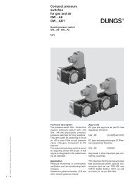
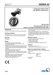
Pressure regulator<br />
<strong>FRS</strong><br />
4.10<br />
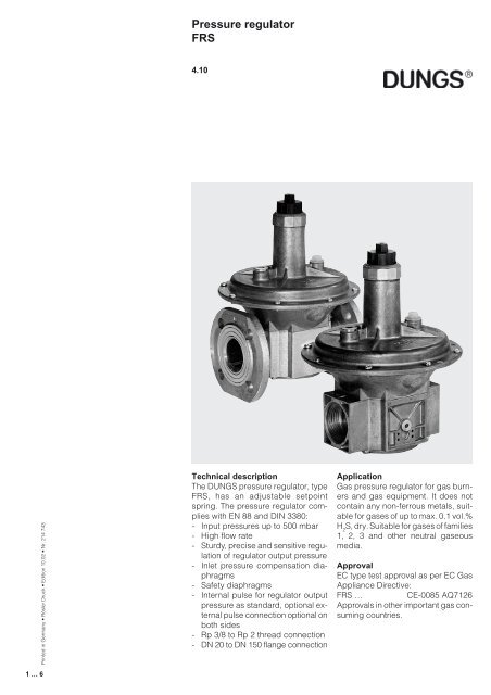
Technical description<br />
The DUNGS pressure regulator, type<br />
<strong>FRS</strong>, has an adjustable setpoint<br />
spring. The pressure regulator complies<br />
with EN 88 and DIN 3380:<br />
- Input pressures up to 500 mbar<br />
- High flow rate<br />
- Sturdy, precise and sensitive regulation<br />
of regulator output pressure<br />
- Inlet pressure compensation diaphragms<br />
- Safety diaphragms<br />
- Internal pulse for regulator output<br />
pressure as standard, optional external<br />
pulse connection optional on<br />
both sides<br />
- Rp 3/8 to Rp 2 thread connection<br />
- DN 20 to DN 150 flange connection<br />
Application<br />
Gas pressure regulator for gas burners<br />
and gas equipment. It does not<br />
contain any non-ferrous metals, suitable<br />
for gases of up to max. 0.1 vol.%<br />
H 2 S, dry. Suitable for gases of families<br />
1, 2, 3 and other neutral gaseous<br />
media.<br />
Approval<br />
EC type test approval as per EC Gas<br />
Appliance Directive:<br />
<strong>FRS</strong> … CE-0085 AQ7126<br />
Approvals in other important gas consuming<br />
countries.
<strong>FRS</strong> Spring-loaded pressure regulator with adjustable setpoint spring. Internal tap of regulator output<br />
pressure. External pulse connections optional, suitable for controlling regulator output pressure.<br />
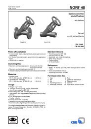
Specifications<br />
Nominal diameters<br />
Pipe thread as per ISO 7/1<br />
Flange<br />
Max. operating pressure<br />
Pressure regulator<br />
Input pressure range<br />
Pressure stage<br />
Output pressure range<br />
Materials of gas-conveying parts<br />
Ambient temperature<br />
Installation position<br />
Measuring/ignition gas connections<br />
Pulse connection<br />
Blow-off line<br />
Pressure taps<br />
1 Breathing plug, blow-off line.<br />
2 Connection for external pulse<br />
G 1/4 ISO 228 screw plug on both<br />
sides, optional<br />
3 G 1/4 ISO 228 screw plug in input<br />
section on both sides<br />
DN 10 15 20 25 40 50 65 80 100 125 150<br />
Rp 3/8 1/2 3/4 1 1 1/2 2<br />
Connection flange as per DIN 2501 Part 1, to fit preweld flanges as per DIN<br />
2633 (PN 16) DN 40 to DN 150, ISO 7005-2 (PN 16)<br />
up to 500 mbar (50 kPa)<br />
Pressure regulator as per EN 88, Class A, Group 2, DIN 3380, RG 10<br />
+ 5 mbar or p2 +2.5 mbar up to 500 mbar<br />
PN 1<br />
2.5 mbar to 150 mbar as a factor of adjustable setpoint spring<br />
Housing: aluminium, steel<br />
Seals and diaphragms: NBR<br />
-15 °C to + 70 °C<br />
Regulator dome from vertically upright to lying horizontally<br />
G 1/4 ISO 228 on both sides in inlet section<br />
Internal in outlet section,<br />
Optional: external on housing on both sides<br />
Blow-off line only required in special cases. Safety diaphragms are installed.<br />
Connection: G 1/4 ISO 228 to Rp 1; from Rp 1 1/2, DN 40: G 1/2 ISO 228<br />
1<br />
2<br />
3<br />
2 … 6
3 … 6<br />
Spring selection<br />
The output pressure is provided by<br />
the force of the installed adjustable<br />
spring and the force due to weight of<br />
Setpoint spring<br />
range [mbar]<br />
Spring colour<br />
Nominal width Rp/DN<br />
Rp 3/8, Rp 1/2<br />
Rp 3/4<br />
Rp 1<br />
Rp 1 1/2, DN 40<br />
Rp 2, DN 50<br />
DN 65, 80<br />
DN 100<br />
DN 125<br />
DN 150<br />
Dimensions<br />
Type<br />
h<br />
<strong>FRS</strong> 503<br />
<strong>FRS</strong> 505<br />
<strong>FRS</strong> 507<br />
<strong>FRS</strong> 510<br />
<strong>FRS</strong> 515<br />
<strong>FRS</strong> 520<br />
<strong>FRS</strong> 5040<br />
<strong>FRS</strong> 5050<br />
<strong>FRS</strong> 5065<br />
<strong>FRS</strong> 5080<br />
<strong>FRS</strong> 5100<br />
<strong>FRS</strong> 5125<br />
<strong>FRS</strong> 5150<br />
d<br />
DN<br />
c<br />
Order No.<br />
Internal<br />
pulse<br />
086 462<br />
070 383<br />
070 391<br />
070 409<br />
058 446<br />
058 628<br />
065 144<br />
065 151<br />
058 792<br />
079 681<br />
082 552<br />
013 250<br />
013 268<br />
2,5…9<br />
Spring 1<br />
brown<br />
069 112<br />
069 195<br />
069 278<br />
058 859<br />
058 925<br />
058 636<br />
083 188<br />
053 082<br />
053 157<br />
b<br />
a<br />
Order No.<br />
External<br />
pulse<br />
220 998<br />
211 817<br />
220 999<br />
210 381<br />
221 000<br />
208 237<br />
214 474<br />
183 600<br />
183 930<br />
183 940<br />
211 019<br />
208 301<br />
208 302<br />
5…13<br />
Spring 2<br />
white<br />
069 120<br />
069 203<br />
069 286<br />
058 867<br />
058 933<br />
058 644<br />
083 196<br />
053 090<br />
053 165<br />
f<br />
g<br />
the moving parts. The pressure regulator<br />
is equipped with the blue spring<br />
No. 4 as standard. By exchanging the<br />
p max.<br />
[mbar]<br />
500<br />
500<br />
500<br />
500<br />
500<br />
500<br />
500<br />
500<br />
500<br />
500<br />
500<br />
500<br />
500<br />
e<br />
5…20<br />
Spring 3<br />
orange<br />
069 138<br />
069 211<br />
069 294<br />
058 875<br />
058 941<br />
058 651<br />
083 204<br />
053 108<br />
053 173<br />
Rp / DN<br />
Rp 3/8<br />
Rp 1/2<br />
Rp 3/4<br />
Rp 1<br />
Rp 1 1/2<br />
Rp 2<br />
DN 40<br />
DN 50<br />
DN 65<br />
DN 80<br />
DN 100<br />
DN 125<br />
DN 150<br />
10…30<br />
Spring 4<br />
blue<br />
Standard<br />
069 146<br />
069 229<br />
069 302<br />
058 883<br />
058 958<br />
058 669<br />
083 212<br />
053 116<br />
053 181<br />
75<br />
75<br />
100<br />
110<br />
150<br />
170<br />
200<br />
230<br />
290<br />
310<br />
350<br />
400<br />
480<br />
h<br />
115<br />
115<br />
130<br />
145<br />
195<br />
250<br />
195<br />
250<br />
285<br />
285<br />
350<br />
400<br />
480<br />
25…55<br />
Spring 5<br />
red<br />
069 153<br />
069 237<br />
069 310<br />
058 891<br />
058 966<br />
058 677<br />
083 220<br />
053 124<br />
053 199<br />
d<br />
24<br />
24<br />
28<br />
33<br />
40<br />
47<br />
65<br />
75<br />
95<br />
95<br />
105<br />
135<br />
160<br />
DN<br />
143<br />
143<br />
165<br />
190<br />
250<br />
310<br />
280<br />
340<br />
405<br />
405<br />
495<br />
635<br />
780<br />
c<br />
adjustable spring, other output pressures<br />
can be adjusted.<br />
30…70<br />
Spring 6<br />
yellow<br />
069 161<br />
069 245<br />
069 328<br />
058 909<br />
058 974<br />
058 685<br />
083 238<br />
053 132<br />
053 207<br />
G 1/4<br />
G 1/4<br />
G 1/4<br />
G 1/4<br />
G 1/2<br />
G 1/2<br />
G 1/2<br />
G 1/2<br />
G 1/2<br />
G 1/2<br />
G 1/2<br />
G 1/2<br />
G 1/2<br />
G 1/4<br />
G 1/4<br />
G 1/4<br />
G 1/4<br />
G 1/4<br />
G 1/4<br />
G 1/4<br />
G 1/4<br />
G 1/4<br />
G 1/4<br />
G 1/4<br />
G 1/4<br />
G 1/4<br />
60…110<br />
Spring 7<br />
black<br />
069 179<br />
069 252<br />
069 336<br />
058 917<br />
058 982<br />
058 693<br />
083 246<br />
053 140<br />
053 215<br />
G 1/8<br />
G 1/8<br />
G 1/8<br />
G 1/8<br />
G 1/4<br />
G 1/4<br />
G 1/4<br />
G 1/4<br />
G 1/4<br />
G 1/4<br />
G 1/4<br />
G 1/4<br />
G 1/4<br />
225<br />
225<br />
245<br />
310<br />
365<br />
450<br />
395<br />
480<br />
590<br />
590<br />
760<br />
1000<br />
1180<br />
100…150<br />
Spring 8<br />
pink<br />
069 187<br />
069 260<br />
069 344<br />
069 351<br />
069 369<br />
069 377<br />
083 253<br />
223 461<br />
223 462<br />
Dimensions [mm] Weight<br />
[kg]<br />
a b c d e f g h<br />
b<br />
a<br />
f<br />
g<br />
e<br />
0.60<br />
0.60<br />
1.00<br />
1.20<br />
2.50<br />
3.50<br />
3.50<br />
5.00<br />
7.50<br />
10.00<br />
16.00<br />
28.00<br />
38.00
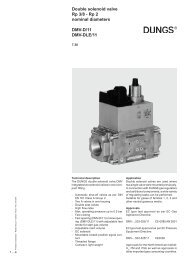
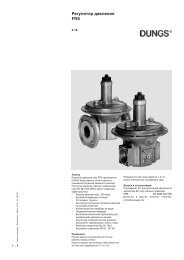
Functional description<br />
Functions according to the force comparison<br />
principle between the force of:<br />
- the adjustable setpoint spring<br />
- the differential pressure at the working<br />
diaphragm<br />
- the force due to weight of the moving<br />
parts<br />
The adjustable spring acts with the<br />
force due to weight of the moving<br />
parts. The output pressure is adjusted<br />
depending on the pretension of the<br />
adjustable spring and the installation<br />
position.<br />
<strong>FRS</strong> 515 sectional drawing<br />
Pressure regulator in operating position<br />
1 Housing<br />
2 Regulating cup<br />
3 Pulse tap, internal<br />
p 1<br />
Instructions<br />
Gas-conveying lines, pulse and connection<br />
lines must be made of steel<br />
and at least PN 1, DN 6. The lines must<br />
be resistant to thermal, chemical and<br />
mechanical loads. The lines must be<br />
durable and resistant to deformation<br />
and cracks.<br />
4 Compensation diaphragm<br />
5 Diaphragm disk<br />
6 Working diaphragm<br />
p 2<br />
Do not route condensate<br />
from lines into the pressure<br />
regulator.<br />
Protect the pressure regulator<br />
from fouling by means of a suitable<br />
dirt trap.<br />
Do not apply combustion<br />
gas or combustion gas air<br />
mixtures to the installation chamber<br />
of the adjustable spring. Pressure<br />
regulators for this application<br />
on request only.<br />
10<br />
7 Safety diaphragm<br />
8 Breathing plug<br />
9 Setpoint spring<br />
10 Adjustment device<br />
9<br />
8<br />
7<br />
6<br />
5<br />
4<br />
3<br />
2<br />
1<br />
4 … 6
5 … 6<br />
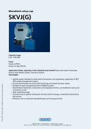
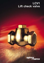
Equipment preselection, blocked<br />
pressure regulators<br />
You can preselect the nominal diameter<br />
using the volumetric flow<br />
pressure drop characteristic of the<br />
pressure regulators in mechanically<br />
open state. The pressure drop be-<br />
Volumetric flow pressure drop characteristic<br />
mechanically open<br />
∆p [mbar]<br />
f =<br />
100<br />
90<br />
80<br />
70<br />
60<br />
50<br />
40<br />
30<br />
20<br />
10<br />
9<br />
8<br />
7<br />
6<br />
5<br />
4<br />
3<br />
2<br />
1<br />
V<br />
°<br />
= V<br />
°<br />
x f<br />
verwendetes Gas/gas used/ gaz utilisé/gas utilizzato Luft/air/air/aria<br />
Dichte Luft<br />
Air density<br />
Densité de l'air<br />
Densità dell'aria<br />
spez. Gweicht des verwendeten Gases<br />
Spec. weight of gas used<br />
poids spécifique du gaz utilisé<br />
peso specifico del gas utilizzato<br />
tween input pressure p 1 and regulator<br />
output pressure p 2 in connection with<br />
the maximum volumetric flow V max determine<br />
the nominal width of the pressure<br />
regulator. The operating point<br />
described by ∆p min and V max is left of<br />
the nominal width of the pressure regu-<br />
Gasart<br />
Type of gas<br />
Type de gaz<br />
Tipo di gas<br />
Erdgas/Nat.Gas/<br />
Gaz naturel/Gas metano<br />
Stadtgas/City gas/<br />
Gaz de ville/Gas città<br />
Flüssiggas/LPG/<br />
Gaz liquide/Gas liquido<br />
Luft/Air/<br />
Air/Aria<br />
lator to be selected.<br />
The pressure drop over blocked pressure<br />
regulators is described by the<br />
"mechanically open" characteristic.<br />
The final determination is performed<br />
according to the dimension specified<br />
by the gas appliance manufacturer.<br />
1 2 4 6 8 10 20 40 60 80 100 200 400 600 800 1000 2000 4000<br />
° 3<br />
Vn [m /h] Luft / Air / Aria dv = 1,00<br />
1 2 4 6 8 10 20 40 60 80 100 200 400 600 800 1000 2000 4000<br />
° 3<br />
Rp 3/8<br />
Rp 1/2<br />
Vn [m /h] Erdgas/Natural gas/Gaz Naturel/Gas metano dv = 0,65<br />
Rp 3/4<br />
Rp 1<br />
DN 40<br />
Rp 11/2<br />
DN 50<br />
Rp 2<br />
Rp 21/2<br />
DN 65<br />
DN 80<br />
DN 100<br />
Basis + 15° C, 1013 mbar, trocken<br />
Based on + 15° C, 1013 mbar, dry<br />
Base + 15° C, 1013 mbar, sec<br />
Base + 15° C, 1013 mbar, secco<br />
Dichte<br />
Density<br />
Densité<br />
Densità<br />
[kg/m 3 ]<br />
0.81<br />
0.58<br />
2.08<br />
1.24<br />
DN 125<br />
DN 150<br />
dv<br />
0.65<br />
0.47<br />
1.67<br />
1.00<br />
f<br />
1.24<br />
1.46<br />
0.77<br />
1.00
Pressure regulator<br />
<strong>FRS</strong><br />
Flow diagram in regulated state, where p = 20 mbar<br />
o o<br />
2<br />
V = 0,05 x V min max<br />
∆p [mbar]<br />
500<br />
400<br />
300<br />
200<br />
150<br />
100<br />
80<br />
60<br />
50<br />
40<br />
30<br />
20<br />
10<br />
8<br />
6<br />
5<br />
4<br />
3<br />
2<br />
1<br />
zone de travail recommandée<br />
1 2 3 4 5 6 8 10 20 30 40 50 60 80 100 200 300 400 600 800 1000 2000<br />
Vn ° 3<br />
[m /h] Luft / Air / Aria dv = 1,00<br />
2 3 4 5 6 8 10 20 30 40 50 60 80 100 200 300 400 600 800 1000 2000<br />
Vn ° 3<br />
[m /h] Erdgas/Natural gas/Gaz Naturel/Gas metano dv = 0,65<br />
We reserve the right to make any changes in the interest of technical progress.<br />
Rp 3/8<br />
Rp 1/2<br />
Rp 3/4<br />
Rp 1<br />
Head Offices and Factory<br />
Karl Dungs GmbH & Co.<br />
Siemensstraße 6-10<br />
D-73660 Urbach, Germany<br />
Telephone +49 (0)7181-804-0<br />
Fax +49 (0)7181-804-166<br />
DN 40<br />
Rp 1 1/2<br />
DN 50<br />
Rp 2<br />
DN 65<br />
DN 80<br />
DN 150<br />
DN 100<br />
DN 125<br />
DN 150<br />
Basis + 15° C, 1013 mbar, trocken<br />
Based on + 15° C, 1013 mbar, dry<br />
Base + 15° C, 1013 mbar, sec<br />
Base + 15° C, 1013 mbar, secco<br />
4000<br />
4000<br />
Postal address<br />
Karl Dungs GmbH & Co.<br />
Postfach 12 29<br />
D-73602 Schorndorf, Germany<br />
e-mail info@dungs.com<br />
Internet www.dungs.com<br />
6 … 6