Power LED chips integrated module PA020 series

Create successful ePaper yourself
Turn your PDF publications into a flip-book with our unique Google optimized e-Paper software.
Av. División del Norte 3115 Col. La Candelaria C.P. 04380<br />
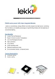
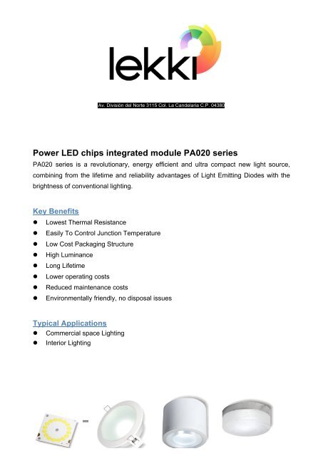
<strong>Power</strong> <strong>LED</strong> <strong>chips</strong> <strong>integrated</strong> <strong>module</strong> <strong>PA020</strong> <strong>series</strong><br />
<strong>PA020</strong> <strong>series</strong> is a revolutionary, energy efficient and ultra compact new light source,<br />
combining from the lifetime and reliability advantages of Light Emitting Diodes with the<br />
brightness of conventional lighting.<br />
Key Benefits<br />
l Lowest Thermal Resistance<br />
l Easily To Control Junction Temperature<br />
l Low Cost Packaging Structure<br />
l High Luminance<br />
l Long Lifetime<br />
l Lower operating costs<br />
l Reduced maintenance costs<br />
l Environmentally friendly, no disposal issues<br />
Typical Applications<br />
l Commercial space Lighting<br />
l Interior Lighting
Precaution<br />
l Don’t touch, push or squish the light emitting area<br />
Do not touch the <strong>LED</strong> Array or resin area during operation. Allow the <strong>LED</strong> Array to cool for<br />
a sufficient period of time before handling. The <strong>LED</strong> Array may reach elevated<br />
temperatures such that it can burn skin when touched.<br />
Emitting area<br />
Revision :3.1 Page 1 of 14<br />
I
Table of Contents<br />
Technology Overview ..................................................................... 3<br />
Average Lumen Maintenance Characteristics ................................ 3<br />
Environmental Compliance ............................................................ 3<br />
Product Nomenclature .................................................................... 4<br />
Dimensions ..................................................................................... 5<br />
Circuit Layout ................................................................................. 6<br />
Absolute Maximum Ratings ............................................................ 7<br />
Forward Voltage Characteristics .................................................... 8<br />
Operating Current and Luminous Flux Characteristics .................. 8<br />
Reliability Test ................................................................................ 9<br />
Color Temperature Characteristics .............................................. 10<br />
Color Spectrum ............................................................................ 10<br />
Recommend Heat Sink Surface Area .......................................... 12<br />
How to measure the junction temperature ................................... 13<br />
Assembly ...................................................................................... 14<br />
Revision :3.1 Page 2 of 14<br />
I
Technology Overview<br />
EDISON ® Light Emitting Diodes Product benefit from a suite of innovations in the fields of<br />
chip technology, packaging, and thermal management. These breakthroughs allow<br />
illumination designers to achieve efficient light engine designs and deliver high brightness<br />
solutions. Furthermore, the COHS ® design can be to reduce thermal resistances between<br />
<strong>chips</strong> and heat sink, easily to control junction temperature.<br />
<br />
Average Lumen Maintenance Characteristics<br />
Lifetime for solid state lighting devices (<strong>LED</strong>s) is typically defined in terms of lumen<br />
maintenance—the percentage of initial light output remaining after a specified period of<br />
time.<br />
EDISON ® to expect that Pacific-S <strong>series</strong> products will deliver, on average 90% lumen<br />
maintenance at 50,000 hours of operation at suggested forward current. This projection is<br />
based on constant current operation with junction temperature maintained at or below<br />
70°C.<br />
Environmental Compliance<br />
EDISON ® Light Emitting Diodes help reduce power consumption and the amount of<br />
hazardous waste entering the environment. All EDISON ® products manufactured by<br />
EDISON ® are RoHS compliant and free of hazardous materials, including lead and<br />
mercury.<br />
Revision :3.1 Page 3 of 14<br />
I
Product Nomenclature<br />
The following table describes the available color, power type etc.<br />
<br />
PA 015 C CU H - 001<br />
Pacific <strong>Power</strong> Packaging<br />
Color Substrate<br />
Type<br />
Order Code Format<br />
Initial <strong>Power</strong> Color Substrate Packaging Type<br />
PA XXX Cool White CU (Copper Heat Sink) Horizontal PN Chip xxx<br />
Notes for Table 1:<br />
“x” Stands for 1 digit<br />
Example:<br />
PA015CCUH-001<br />
Neutral White AL(Aluminum Heat Sink) Vertical PN Chip<br />
Warm White FR (Fiber Reinforced Plastic) Flip-Chip<br />
AC <strong>Power</strong><br />
Pacific Series / 15 watts / Cool White Color / Copper Heat Sink Substrate / Horizontal PN<br />
Chip Package / Type 001.<br />
Revision :3.1 Page 4 of 14<br />
I
Dimensions<br />
Color code are replaced with question mark “?” in product code.<br />
<strong>PA020</strong>?CUH-001&002<br />
<br />
Notes:<br />
Top View<br />
Front View<br />
1. Solder pads are labeled “+” and “-“ to denote positive and negative, respectively.<br />
2. Drawings are not to scale.<br />
3. Drawing dimensions are in millimeters.<br />
4. Unless otherwise specified, tolerances are ± 0.20mm.<br />
Bottom View<br />
5. The optical center of the <strong>LED</strong> Array is defined by the mechanical center of the array.<br />
Revision :3.1 Page 5 of 14<br />
I
Circuit Layout<br />
Product code below neglect color、substrate and package code, for example instead of<br />
PA015CCUH-001 with PA015-001.<br />
<strong>PA020</strong>-001<br />
<strong>PA020</strong>-002<br />
Revision :3.1 Page 6 of 14<br />
I
Absolute Maximum Ratings<br />
The following table describes absolute maximum ratings of Pacific-S <strong>series</strong>. Please refer<br />
to circuit layout on previous page for DC forward current & voltage selection.<br />
Product code below neglect “PA”、color、substrate and package code, for example instead<br />
of PA015 CCUH-001 with 015-001.<br />
Table 2.<br />
Parameter Range Unit Symbol<br />
<strong>LED</strong> Junction Temperature
Forward Voltage Characteristics<br />
The following tables describe forward voltage of Pacific-S005 <strong>series</strong>. Please note that the<br />
all forward voltage range is based on constant driving current. Do not base on the values<br />
below to design a constant voltage system.<br />
Product code below neglect color、substrate and package code, for example instead of<br />
PA015CCUH-001 with PA015-001.<br />
<strong>Power</strong> Min. Voltage<br />
(VF)<br />
Table 3.<br />
Typ.Voltage<br />
(VF)<br />
Max.Voltage<br />
(VF)<br />
<strong>PA020</strong>-001 11.9 13.2 14.5 V<br />
<strong>PA020</strong>-002 23.8 26.4 29.0<br />
Notes for Table 3:<br />
Forward voltage is measured with an accuracy of ±10%<br />
Operating Current and Luminous Flux Characteristics<br />
The following tables describe luminous flux at Ta=25°C for Pacific-S <strong>series</strong> at DC forward current<br />
suggested above.<br />
Unit<br />
Product code below neglect “PA”、color、substrate and package code, for example instead of<br />
PA015CCUH-001 with 015-001.<br />
Table 4.<br />
Color 020-001 020-002 Unit<br />
Cool White 4058 4058 lm<br />
Neutral White 3785 3785<br />
Warm White 3238 3238<br />
Notes for Table 4:<br />
1. Luminous flux is measured with an accuracy of ±10% with 170°<br />
Revision :3.1 Page 8 of 14<br />
I
Reliability Test<br />
The following table describes operating life, mechanical, and environmental tests<br />
performed on EDISON ® Pacific-S <strong>series</strong>.<br />
Table 5.<br />
Stress Test Test Description<br />
Revision :3.1 Page 9 of 14<br />
I<br />
Stress<br />
Duration<br />
Natural Drop Equivalent drop height 112cm *<br />
High temperature<br />
operation or storage<br />
125°C 1000 hours<br />
High temperature &<br />
Humidity<br />
85°C/85%RH 1000 hours<br />
Temperature Cycle<br />
–40/115°C,15min dwell/<br />
Color Temperature Characteristics<br />
The following tables describe color temperature of Pacific-S <strong>series</strong>.<br />
Product code below use “x” instead of power、substrate and package code, for example<br />
instead of PA015CCUH-001 with PAxxxCxxx-xxx.<br />
Table 6.<br />
Order Code Color λd / CCT<br />
Min. Max<br />
PAxxxCxxx-xxx Cool White 5000 10000 K<br />
PAxxxNxxx-xxx Neutral White 3700 5000 K<br />
PAxxxWxxx-xxx Warm White 2600 3700 K<br />
Notes for Table 6:<br />
1. CCT is measured with an accuracy of ± 200K.<br />
Color Spectrum<br />
Cool White Color Spectrum<br />
Unit<br />
Cool White Spectrum<br />
350 400 450 500 550 600 650 700 750 800 850 900 950 1000 1050<br />
Wavelength(nm)<br />
<br />
Revision :3.1 Page 10 of 14<br />
I
Neutral White Color Spectrum<br />
<br />
Warm White Color Spectrum<br />
Neutral White Spectrum<br />
350 400 450 500 550 600 650 700 750 800 850 900 950 1000 1050<br />
Wavelength(nm)<br />
Warm White Spectrum<br />
350 400 450 500 550 600 650 700 750 800 850 900 950 1000 1050<br />
Wavelength(nm)<br />
<br />
Revision :3.1 Page 11 of 14<br />
I
Recommend Heat Sink Surface Area<br />
The following tables describe recommend heat sink surface area to make sure the<br />
junction temperature Tj below 70°C and ensure the product’s life time of Pacific-S <strong>series</strong>.<br />
Chip Distribution<br />
Square<br />
Circle<br />
*Note 1<br />
Note 1 : Describe about die distribution.<br />
Square : example as below<br />
Circle : example as below<br />
Table 7.<br />
Wattage<br />
Suggested Surface<br />
(W)<br />
Area<br />
(cm 2 )<br />
5 150<br />
7 300<br />
10 500<br />
15 800<br />
20 1000<br />
30 2500<br />
40 3200<br />
50 4000<br />
60 >4000<br />
100 >15000<br />
120 >20000<br />
10 500<br />
15 500<br />
20 500<br />
Test point<br />
Revision :3.1 Page 12 of 14<br />
I
How to measure the junction temperature<br />
It’s very easily to make sure the junction temperature by measure the temperature of test<br />
point designed on the substrate near the <strong>chips</strong>. By choose suitable heat sink and measure<br />
the test point temperature to make sure the junction temperature at least below 80°C .<br />
1. Attach product on the heat-sink<br />
with high heat conductive paste.<br />
Test point.<br />
Via diameter 1.0mm<br />
2. Let the thermal wire contact the<br />
via bottom metal and fixed.<br />
Suggest thermal wire diameter<br />
below 0.15mm<br />
Thermal meter<br />
3. Light on and waiting for heat equilibrium.<br />
The equilibrium time depend on the<br />
heat-sink size you chose. Normally 2.5hr<br />
waiting time is necessary.<br />
4. Read temperature and plus 3 degree will<br />
be the junction temperature.<br />
Revision :3.1 Page 13 of 14<br />
I
Assembly<br />
We suggested using Pacific-S will be easier to apply to in lighting application. It’s can use<br />
screws to fix at lampshade or metal utilities. We strongly recommended using as graphite<br />
between lampshade or utilities metal.<br />
Graphite<br />
Heat Sink<br />
Drawing Not to Scale<br />
<br />
For the Circle emitter products (020-001&002), preferred screw mounting locations are<br />
indicated in Figure7.<br />
Screw<br />
Emitter<br />
<br />
Graphite 0.5t/mm (Reference)<br />
Pacific-S <strong>series</strong> (Reference)<br />
Heat Sink (Reference)<br />
Revision :3.1 Page 14 of 14<br />
I