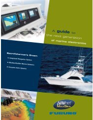
TZTBB Installation Manual - Furuno USA
TZTBB Installation Manual - Furuno USA
TZTBB Installation Manual - Furuno USA

You also want an ePaper? Increase the reach of your titles
YUMPU automatically turns print PDFs into web optimized ePapers that Google loves.
<strong>Installation</strong> <strong>Manual</strong><br />
Multi Function Display<br />
Black Box Type<br />
<strong>TZTBB</strong><br />
SAFETY INSTRUCTIONS ................................................................................................ i<br />
SYSTEM CONFIGURATION ........................................................................................... ii<br />
EQUIPMENT LISTS........................................................................................................ iii<br />
1. MOUNTING..............................................................................................................1-1<br />
1.1 Mounting Considerations ...................................................................................................1-1<br />
1.2 Processor Unit ...................................................................................................................1-1<br />
1.3 Switch Box .........................................................................................................................1-2<br />
2. WIRING....................................................................................................................2-1<br />
2.1 Wiring Instructions .............................................................................................................2-1<br />
2.2 CAN bus/NMEA0183 Data Conversion .............................................................................2-9<br />
2.3 Example NavNet TZtouch System Configurations...........................................................2-12<br />
3. SETTING UP THE EQUIPMENT .............................................................................3-1<br />
3.1 How to Set Time Zone, Language and Units .....................................................................3-4<br />
3.2 Menu Initial Setup ..............................................................................................................3-5<br />
3.3 How to Set up the Radar....................................................................................................3-8<br />
3.4 How to Set up the Sounder..............................................................................................3-11<br />
3.5 Wireless LAN Setting .......................................................................................................3-12<br />
4. HOW TO INSTALL THE HDD .................................................................................4-1<br />
4.1 Hard Disk Drive (HDD).......................................................................................................4-1<br />
PACKING LIST............................................................................................................ A-1<br />
OUTLINE DRAWINGS ................................................................................................ D-1<br />
INTERCONNECTION DIAGRAM ................................................................................ S-1<br />
www.furuno.com<br />
All brand and product names are trademarks, registered trademarks or service marks of their respective holders.
SAFETY INSTRUCTIONS<br />
The installer must read the safety instructions before attempting to install the equipment.<br />
WARNING<br />
CAUTION<br />
(Examples of symbols)<br />
Indicates a potentially hazardous situation which, if not<br />
avoided, could result in death or serious injury.<br />
Indicates a potentially hazardous situation which, if not<br />
avoided, may result in minor or moderate injury.<br />
Warning, Caution Prohibitive Action Mandatory Action<br />
WARNING<br />
ELECTRICAL SHOCK HAZARD<br />
Do not open the equipment<br />
unless totally familiar with<br />
electrical circuits.<br />
Only qualified personnel should<br />
work inside the equipment.<br />
Turn off the power at the<br />
switchboard before beginning<br />
the installation.<br />
Fire or electrical shock can result<br />
if the power is left on.<br />
Be sure that the power supply is<br />
compatible with the voltage<br />
rating of the equipment.<br />
Connection of an incorrect power<br />
supply can cause fire or damage<br />
the equipment.<br />
CAUTION<br />
Ground the equipment to prevent<br />
electrical shock and mutual<br />
interference.<br />
Use the proper fuse.<br />
Use of an incorrect fuse may<br />
damage the equipment.<br />
Observe the following compass safe<br />
distances to prevent interference to a<br />
magnetic compass:<br />
MPU-002<br />
Standard<br />
compass<br />
Steering<br />
compass<br />
0.45 m 0.30 m<br />
PSD-002 0.35 m 0.30 m<br />
i
SYSTEM CONFIGURATION<br />
Basic configuration is shown with solid line.<br />
Note 1: Do not connect or disconnect the DVI cable between <strong>TZTBB</strong> and the touch monitor while<br />
<strong>TZTBB</strong> is powered.<br />
Note 2: When the two monitors are connected, the resolutions and the aspect ratio should match<br />
between two monitors. The two monitors show same images (compatible with clone mode only).<br />
ii<br />
POWER SUPPLY<br />
UNIT*<br />
PSU-017<br />
RADAR SENSOR<br />
DRS2D/DRS4D<br />
12-24 VDC<br />
NAVpilot-700<br />
SC-30<br />
GP-330/WS-200<br />
FI-50, etc.<br />
IF-NMEA2K1/2<br />
CCD Camera<br />
CCD Camera<br />
FI-5002<br />
OR<br />
12/24 VDC<br />
Environmental category<br />
Sensor units: Exposed to the weather<br />
All other units: Protected from the weather<br />
12-24 VDC<br />
RADAR SENSOR<br />
DRS4A/DRS6A/DRS12A/DRS25A<br />
HUB -101<br />
Processor Unit<br />
MPU-002<br />
Switch Box<br />
PSD-002<br />
POWER SUPPLY UNIT*<br />
PSU-012/PSU-013<br />
FAR-2xx7 series<br />
FCV-1150, BBDS1,<br />
DFF series<br />
FA-30/50<br />
FAX-30<br />
IP Camera<br />
FUSION-Link equipment<br />
Network equipment<br />
Touch Monitor<br />
Touch Monitor<br />
Event SW<br />
External Buzzer<br />
Speed Alarm<br />
Power input for CAN bus<br />
*: The power supply unit is required when you connect the radar sensor.<br />
PSU-012: w/DRS2D/4D/4A/6A/12A<br />
PSU-013: w/DRS25A<br />
PSU-017: w/DRS2D/4D<br />
For details of the power supply unit, see the installation manual of the radar sensor (IME-35670).
EQUIPMENT LISTS<br />
Standard supply<br />
Name Type Code No. Qty Remarks<br />
Processor Unit MPU-002 - 1<br />
Switch Box PSD-002 - 1<br />
<strong>Installation</strong> Materials<br />
CP19-01700 000-022-530 1<br />
CP19-01701<br />
Accessories FP19-01801 001-205-650 1<br />
Spare Parts SP19-01401 001-205-630 1 Fuses<br />
Optional supply<br />
Name Type Code No. Remarks<br />
Joint Box TL-CAT-012 000-016-714-01 For LAN network<br />
NMEA2000-<br />
Interface Unit<br />
IF-NMEA2K1 -<br />
NMEA Data<br />
Converter<br />
IF-NMEA2K2 -<br />
Network HUB HUB-101 -<br />
Junction Box FI-5002 -<br />
Rectifier RU-3423 000-030-443<br />
PR-62 000-013-484 100VAC<br />
000-013-485 110VAC<br />
000-013-486 220VAC<br />
000-013-487 230VAC<br />
RU-1746B-2 000-030-439<br />
CAN bus Cable<br />
Assy.<br />
M12-05BM+05BF-010 001-105-750-10 w/connectors (light), 1 m<br />
M12-05BM+05BF-020 001-105-760-10 w/connectors (light), 2 m<br />
M12-05BM+05BF-060 001-105-770-10 w/connectors (light), 6 m<br />
M12-05BFFM-010 001-105-780-10 w/connector (light), 1 m<br />
M12-05BFFM-020 001-105-790-10 w/connector (light), 2 m<br />
M12-05BFFM-060 001-105-800-10 w/connector (light), 6 m<br />
CB-05PM+05BF-010 000-167-968-10 w/connectors (heavy), 1 m<br />
CB-05PM+05BF-020 000-167-968-10 w/connectors (heavy), 2 m<br />
CB-05PM+05BF-060 000-167-970-10 w/connectors (heavy), 6 m<br />
CB-05BFFM-010 000-167-971-10 w/connector (heavy), 1 m<br />
CB-05BFFM-020 000-167-972-10 w/connector (heavy), 2 m<br />
CB-05BFFM-060 000-167-973-10 w/connector (heavy), 6 m<br />
DVI-D Cable Assy. DVI-D/D S-LINK 5M 001-132-960-10 24 pin, for video output, 5 m<br />
DVI-D/D S-LINK 10M 001-133-980-10 24 pin, for video output, 10 m<br />
External Buzzer OP03-136 000-086-443 Buzzer: PKB5-3A40<br />
Network (LAN)<br />
Cable<br />
MOD-Z073-030+ 000-167-171-10 LAN cable, straight, 2 pairs, 3 m<br />
MOD-Z072-020+ 001-167-880-10 LAN cable, cross-pair, 2 m<br />
MOD-Z072-050+ 001-167-890-10 LAN cable, cross-pair, 5 m<br />
MOD-Z072-100+ 001-167-900-10 LAN cable, cross-pair, 10 m<br />
iii
EQUIPMENT LISTS<br />
Name Type Code No. Remarks<br />
CAN bus<br />
Connector<br />
SS-050505-FMF-<br />
TS001<br />
000-168-603-10<br />
Micro style: 3<br />
NC-050505-FMF-<br />
TS001<br />
000-160-807-10<br />
Mini style: 2,<br />
micro style: 1<br />
LTWMC-05BMMT-<br />
SL8001<br />
000-168-604-10<br />
Micro style, male,<br />
termination resistor<br />
LTWMN-05AMMT-<br />
SL8001<br />
000-160-508-10<br />
Mini style, male,<br />
termination resistor<br />
LTWMC-05BFFT-<br />
SL8001<br />
000-168-605-10<br />
Micro style, female,<br />
termination resistor<br />
LTWMN-05AFFT-<br />
SL8001<br />
000-160-509-10<br />
Mini style, female,<br />
termination resistor<br />
FRU-0505-FF-IS 001-077-830-10 w/inline terminator<br />
MJ Cable Assy. MJ-A6SPF0016-005C 000-159-689-10 for FAX-30<br />
Operator’s <strong>Manual</strong> OME-44700-* 000-176-016-1* English<br />
OMJ-44700-* 000-176-015-1* Japanese<br />
iv
1. MOUNTING<br />
1.1 Mounting Considerations<br />
When selecting a mounting location for <strong>TZTBB</strong>, keep the following in mind:<br />
• The temperature at the mounting location shall be between -15°C and +55°C (wireless<br />
LAN: 0°C and +55°C).<br />
• The humidity at the mounting location shall be 93% or less at 40°C.<br />
• Locate the unit away from exhaust pipes and ventilators.<br />
• The mounting location should be well ventilated.<br />
• Mount the unit where shock and vibration are minimal (comply with IEC 60945<br />
Ed.4).<br />
• Keep the unit away from electromagnetic field generating equipment such as motors<br />
and generators.<br />
• For maintenance and checking purposes, leave sufficient space around the unit and<br />
leave slack in cables. Minimum recommended space is shown in the outline drawings.<br />
• A magnetic compass will be affected if the equipment is placed too close to it. Observe<br />
the compass safe distances shown in the SAFETY INSTRUCTIONS to prevent<br />
disturbance to the magnetic compass.<br />
1.2 Processor Unit<br />
The processor unit MPU-002 can be mounted on the tabletop or a bulkhead. Refer to<br />
the outline drawing for mounting dimensions. For bulkhead mounting, be sure the unit<br />
bottom is oriented downward.<br />
Tabletop/ bulkhead mount<br />
1. Decide the munting location for the unit.<br />
2. Make four pilot holes for self-tapping screws in the mounting location.<br />
3. Screw the self-tapping screws (φ6x20, 4 pcs.) into the pilot holes, leaving a clearance<br />
of 5 mm.<br />
4. Hang the unit on the screws.<br />
5. Fasten all screws.<br />
1-1
1. MOUNTING<br />
1.3 Switch Box<br />
1-2<br />
The switch box PSD-002 is designed to be flush mounted on a flat bulkhead. Refer to<br />
the outline drawing for mounting dimensions.<br />
Procedure<br />
1. Make a cutout in the mounting location as shown below.<br />
R10<br />
95±1<br />
86±1<br />
Cutout dimensions<br />
2. Insert the sponge to the switch box from the rear side.<br />
3. Set the unit to the cutout and fix the flush mount fixture from the rear side with two<br />
screws.<br />
4. Tighten the wing bolts to fasten the switch box.<br />
5. Tighten the wing nuts to fasten the flush mount fixture.<br />
Protector for screw<br />
Wing nut<br />
Wing bolt<br />
Mounting panel<br />
Flush mount fixture
2. WIRING<br />
2.1 Wiring Instructions<br />
MOD-WPAS0001-030+<br />
(Supplied, 3 m)<br />
Network 1/2/3<br />
TO:<br />
- HUB-101<br />
(TL-CAT-012)<br />
- DRS series<br />
- TZT9/14/BB<br />
- DFF series<br />
- FUSION-Link<br />
equipment<br />
- Other sensor<br />
DVI-OUT0<br />
DVI-D/D S-LINK cable<br />
(Supplied, 24 pin, 0.5 m)<br />
LINE OUT<br />
Video IN<br />
1/2<br />
DVI-IN<br />
DVI-D/D<br />
S-LINK cable<br />
2.1.1 NETWORK ports<br />
DVI-D for<br />
External Monitor<br />
(DVI-OUT1/2)<br />
USB cable<br />
Touch Monitor<br />
MULTI Port<br />
TO:<br />
- External Buzzer<br />
- Speed Alarm<br />
- Power for CAN bus<br />
- Event Switch<br />
USB<br />
1/2/3/4<br />
Switch Box<br />
PSD-002<br />
FRUDD-18AFFM-<br />
L180 cable<br />
(Supplied, 18 pin,<br />
2 m)<br />
Ground terminal<br />
TO: Ship's ground<br />
(IV-8sp., Local supply)<br />
Power TO: 12 - 24 VDC<br />
MJ-A3SPF0017-050ZC, 5 m<br />
(w/ 10A FUSE, supplied)<br />
CAN bus CABLE<br />
M12-05BM+05BF/<br />
M12-05BFFM cable<br />
(Option, 1/2/6 m)<br />
CAN bus T-connector<br />
(SS-050505 FMF/<br />
NC-050505-FMF, option)<br />
or<br />
TO: FI-5002<br />
<strong>TZTBB</strong> uses a standard TCP/IP Ethernet to share radar/sounder images and other<br />
navigation information from devices connected to the network system. In any single<br />
NavNet TZtouch network, a combination of up to six TZT series devices may be connected<br />
to each other. All NavNet TZtouch network components have integrated regular<br />
RJ45 Ethernet port(s), three on <strong>TZTBB</strong>. The MOD-WPAS0001-030+ cable<br />
(supplied) connects to equipment in the network.<br />
2-1
2. WIRING<br />
2.1.2 MULTI port<br />
2-2<br />
Use the cable assembly FRUDD-18AFFM-L180 (supplied, 2 m)<br />
for the event switch, external buzzer, speed alarm and the power<br />
for CAN bus. This cable has an 18-pin connector. For example, a<br />
MOB contact closure input may be connected to pin 15 and 11*.<br />
*Note that any <strong>TZTBB</strong> interfaces to virtually any MOB system or<br />
event switch (point save) contact closure signal using these pins.<br />
2 1<br />
6 5 4 3<br />
11<br />
10 9 8 7<br />
15 14 13 12<br />
18 17 16<br />
Pin No. Color Function Remark (Port No.)<br />
18 Light green NET-C IN (0V) CAN bus Power IN. When 12V DC power is<br />
17 Pink NET-S IN (+12V IN)<br />
applied to these pins, the CAN bus port will be<br />
powered (up to 1 ampere).<br />
16 Purple Shield<br />
15 White BUZZER or EVENT IN<br />
External Buzzer Output or MOB/Event Input<br />
(Contact Closure)<br />
14 Gray SPEED-ALARM C Speed alarm contact. Can trigger an external<br />
13 Yellow SPEED-ALARM H<br />
alarm or device when speed exceeds the limit<br />
specified.<br />
12 Black/White +12V External buzzer power ONLY (100 mA max.)<br />
11 Black GND GND for Event/MOB Input<br />
10 Blue/White - For debug<br />
9 Blue -<br />
8 Green/White -<br />
7 Green -<br />
6 Orange/White -<br />
5 Orange GND<br />
4 Brown/White DC_N<br />
3 Brown PWR_SW<br />
2 Red/White GND<br />
1 Red GND
2.1.3 CAN bus port<br />
2. WIRING<br />
Every <strong>TZTBB</strong> has one CAN bus port (micro style connector). All TZT9/14 MUST be<br />
connected to the same CAN bus backbone. However, the <strong>TZTBB</strong> and DRS (radar<br />
sensor) CAN bus ports cannot be connected together. The <strong>TZTBB</strong> and DRS (radar<br />
sensor) use “Ethernet Bridging” to link the DRS CAN bus and the <strong>TZTBB</strong> CAN bus<br />
data. Refer to paragraph 2.2.1 for more information. Note that the <strong>TZTBB</strong> CAN bus<br />
port is not powered unless external power is applied to the FRUDD-18AFFM-L180 cable<br />
of MULTI port and must be connected to a properly configured CAN bus network.<br />
What is CAN bus?<br />
CAN bus is a communication protocol that shares multiple data and signals through a<br />
single backbone cable. You can simply connect any CAN bus devices onto the backbone<br />
cable to expand your network onboard. With CAN bus, IDs are assigned to all<br />
the devices in the network, and the status of each sensor in the network can be detected.<br />
All the CAN bus devices can be incorporated into the NMEA2000 network. For<br />
detailed information about CAN bus wiring, see “<strong>Furuno</strong> CAN bus Network Design<br />
Guide” (Type: TIE-00170) on Tech-Net.<br />
DRS radar sensor<br />
In addition to the CAN bus port found on<br />
the <strong>TZTBB</strong>, all DRS radar sensors have<br />
one powered CAN bus port (terminal strip<br />
connector). You may directly connect various<br />
<strong>Furuno</strong> CAN bus sensors to the DRS<br />
radar sensor without having to run a separate<br />
CAN bus cable to the mast. The total<br />
number of sensors that can be connected<br />
to the CAN bus DRS port without external<br />
Resistor assembly<br />
(120 OHM-1007#24-L50,<br />
supplied with DRS)<br />
Twisting and<br />
soldering<br />
power connection depends on power consumption. The DRS can supply up to 1 amp<br />
(20LEN) to the DRS CAN bus network. Note that the CAN bus network connected to<br />
the DRS is its own independent CAN bus backbone and needs to be terminated at<br />
both ends by a terminating resistor. A 120 Ohm resistor is standard supply with the<br />
DRS to terminate the CAN bus. For example, if you install a SC-30/WS-200 with the<br />
DRS CAN bus port, you must have two terminators on the backbone. One can be at<br />
the sensor and the other located inside the DRS as shown in the inset at right.<br />
Blue<br />
WS-200 SC-30<br />
In the above example, the terminating resistors are<br />
necessary at DRS and SC-30.<br />
Refer to the DRS <strong>Installation</strong> <strong>Manual</strong> for more information about connection.<br />
White<br />
CAN bus cable<br />
2-3
2. WIRING<br />
2-4<br />
NMEA0183 equipment<br />
To connect an NMEA0183 equipment to <strong>TZTBB</strong>, use the CAN bus network via the optional<br />
NMEA data converter IF-NMEA2K2 (or IF-NMEA2K1). This NMEA connection<br />
can accept a baud rate of 4800 or 38400.<br />
Heading input to <strong>TZTBB</strong> allows functions such as Radar Overlay and course stabilization<br />
(North up, Course up, etc.) in the radar operating modes. The NMEA0183<br />
heading refresh rate needs to be 100 ms in order for any radar function to work properly.<br />
NMEA0183 heading can be accepted on any CAN bus port at a baud rate up to<br />
38400 bps. In other words, data sent (IF-NMEA) and received (<strong>TZTBB</strong>) must use the<br />
same baud rate for each individual data port.<br />
Note: Heading data from a CAN bus source/sensor is always at the correct refresh<br />
speed for the DRS ARPA function.<br />
2.1.4 VIDEO, DVI-D, AUDIO or USB ports<br />
How to connect VIDEO, DVI-D, AUDIO or USB ports<br />
The above-mentioned ports are behind the connector cover on the rear panel. Access<br />
the ports and connect cables as shown in the procedure below.<br />
Note 1: The processor unit must be mounted indoors to do this connection because<br />
of reduced waterproofing.<br />
Note 2: DVI OUT1 takes priority over DVI OUT2. Use DVI OUT1 port and USB2 to<br />
connect a single touch monitor.<br />
1. Attach waterproofing tubes to the DVI cables.<br />
Open the slit on the waterproofing tube and set the tube to the DVI cable between<br />
the connector of port DVI-D OUT0 and the EMI core.<br />
Attach supplied cable ties at each end of the tube.<br />
Note: Attach the waterproofing tube also to the external DVI monitor cable whose<br />
outer diameter is less than 9 mm.<br />
EMI core<br />
Fix with<br />
cable ties<br />
DVI cable connector<br />
Waterproofing tube
2. WIRING<br />
2. Attach the DVI-D, Video composite and Audio cable connectors to their respective<br />
ports.<br />
Audio OUT<br />
Video IN 1/2<br />
3. Set the waterproofing gasket to the boot cover then pass the cables through the<br />
boot cover.<br />
4. Fasten the boot cover with four binding screws.<br />
5. Attach the fixing plate to the boot cover.<br />
6. Pass the cables through appropriate holes in the gasket. The largest hole is for<br />
the DVI-D cable.<br />
7. Set the cable adapter to the entrance of the boot cover.<br />
8. Peel off the seal from the slots to be used on the fixing metal.<br />
9. Fasten the fixing metal to the boot cover with two binding screws.<br />
Binding screw<br />
(2 pcs.)<br />
DVI-D OUT0<br />
Fixing metal<br />
Binding screw<br />
(4 pcs.)<br />
Fixing plate<br />
Gasket<br />
Fixing metal<br />
Peel off the seal<br />
from the slots to<br />
be used<br />
Waterproofing gasket<br />
Boot cover<br />
2-5
2. WIRING<br />
2-6<br />
Cable ties for<br />
fixing<br />
10. Fix the cables to the cable clamp with cable ties (2 pcs. each).<br />
Attach a cable tie at the base of waterproofing tube.<br />
Note: Cable ties are necessary for waterproofing. Do not fail to attach them.<br />
Cable ties for<br />
waterproofing<br />
Add a tie for<br />
waterproofing<br />
Fix the cables<br />
with cable ties<br />
Bottom side<br />
11. Pass the opposite end of the DVI-D cable (connected at step 1) through the outside<br />
entrance of the connector cover.<br />
12. Connect the plug to the DVI-IN port and fasten the plug with the screws on the<br />
plug.<br />
13. Pass the DVI-D cable and USB cable for external touch monitor through the outside<br />
entrance of the connector cover.<br />
14. Connect the DVI-D plug to the DVI OUT1 port and connect the USB plug to the<br />
USB2 port.<br />
15. If the second touch monitor is installed, connect the DVI-D plug to the DVI OUT2<br />
port and connect the USB plug to the USB3 port.<br />
16. Pass the power plug and USB plug from the switch box PSD-002 through the connector<br />
cover then connect them to the PWR SW port and the USB1 port, respectively.<br />
17. If another USB device is installed, connect the USB plug to USB4 port.<br />
18. Fasten the connector cover to the unit with six binding screws.<br />
19. Attach the fixing plate1 to the entrance of the connector cover.<br />
20. Pass the cables through appropriate holes in the gasket.<br />
21. Set the gasket to the entrance of the cover.<br />
Insert the gasket to the<br />
entrance of cover so the slits in<br />
the holes face downward.
22. Peel off the seal from the slots to be used on the fixing plate2.<br />
23. Attach the fixing plate2 to the entrance of the connector cover.<br />
24. Fasten the fixing metal to the connector cover with three binding screws.<br />
Binding screw<br />
(3 pcs.)<br />
Fixing plate2<br />
Binding screw<br />
(6 pcs.)<br />
Peel off the seal from<br />
the slots to be used<br />
Connector cover<br />
Fixing plate 1<br />
Gasket<br />
Fixing plate 2<br />
Fixing metal<br />
2. WIRING<br />
25. Fix the cables to the cable clamp with cable ties (2 pcs. each).<br />
Attach a cable tie at the base of waterproofing tube projection.<br />
Note: Cable ties are necessary for waterproofing. Do not fail to attach them.<br />
Add a tie for waterproofing<br />
Fix with cable ties<br />
2-7
2. WIRING<br />
2-8<br />
Video input<br />
<strong>TZTBB</strong> can use regular analog video inputs (PAL or NTSC) that connect to the <strong>TZTBB</strong><br />
directly or use IP cameras that connect directly to the network HUB. IP cameras can<br />
be seen by all <strong>TZTBB</strong> connected to the NavNet TZtouch network, unlike analog video<br />
that can be viewed only on the equipment where the source is connected. Additionally<br />
some IP cameras can be controlled from <strong>TZTBB</strong>.<br />
Analog video<br />
The <strong>TZTBB</strong> processor unit has two analog video inputs (PAL/NTSC) on 2 mm RCA<br />
type connectors located on the rear of the equipment. For this connection, the following<br />
cable is necessary (local supply).<br />
• 3C2V (Japan Industrial Standard (JIS), or the equivalent) coaxial cable<br />
(impedance: 75 Ω)<br />
IP camera<br />
IP cameras are network devices that connect directly to a HUB. Up to four IP cameras<br />
can be connected to one NavNet TZtouch network. At this time, only AXIS IP cameras<br />
that support MPEG4 video are functional in the network. For more details, see the operator’s<br />
manual for the AXIS IP cameras.<br />
DVI-D (external monitor)<br />
A DVI monitor is required for the <strong>TZTBB</strong>. The plug is DVI-D format and only a DVI-D<br />
monitor with VESA DDC (Display Data Channel) can be connected. The <strong>TZTBB</strong> uses<br />
the monitor information (EDID) given via DDC to output the video data with the appropriate<br />
resolution. <strong>Furuno</strong> offers two lengths of DVI-D cables, 5 m and 10 m.<br />
Note: When a second monitor is used, use the same aspect ratio and resolutions<br />
monitor as the first monitor. The DVI-OUT1 port should be used in DVI-D connection.<br />
If this port is converted into HDMI, the DVI-OUT2 port may not transmit the picture signal.<br />
USB port<br />
The <strong>TZTBB</strong> has six USB Ver. 2.0 ports. The USB port2/3 are used to connect USB<br />
Touch Monitor (compatible with Windows ® 7 HID generic driver) and USB port 1 is<br />
used to connect to switch box for SDXC card. The USB port5/6 are used to connect<br />
the devices for internal installation.<br />
Audio<br />
Conductor<br />
S = 0.19 mm 2<br />
φ = 0.5 mm<br />
Insulator<br />
Outputs the audio line from the left-hand connector.<br />
Shield<br />
Vinyl sheath
2.2 CAN bus/NMEA0183 Data Conversion<br />
2.2.1 Connection with DRS radar sensor<br />
WS-200<br />
2. WIRING<br />
All DRS radar sensors have one CAN bus port (Terminal Block connector). You can<br />
directly connect <strong>Furuno</strong> CAN bus sensors to the DRS radar without having to run another<br />
CAN bus cable up the mast. In this case, each separate CAN bus network (the<br />
DRS CAN bus and the ship CAN bus) will be “Bridged” together via the Ether Network.<br />
Note that the <strong>TZTBB</strong> and DRS CAN bus ports must not be connected together.<br />
Connection of multiple <strong>TZTBB</strong>s, no DRS radar sensor<br />
Connect multiple <strong>TZTBB</strong>s with Ethernet and CAN bus cables.<br />
<strong>TZTBB</strong><br />
(MPU-002)<br />
Ethernet cable<br />
<strong>TZTBB</strong><br />
(MPU-002)<br />
Connection of <strong>TZTBB</strong> and DRS radar sensor<br />
CAN bus cable<br />
Connect <strong>TZTBB</strong> to DRS radar sensor with Ethernet cable.<br />
<strong>TZTBB</strong><br />
(MPU-002)<br />
RADAR SENSOR<br />
DRS2D/4D<br />
DRS4A/6A<br />
DRS12A/25A<br />
POWER SUPPLY UNIT<br />
PSU-012: w/DRS2D/4D/4A/6A/12A<br />
PSU-013: w/DRS25A<br />
: Ethernet cable<br />
: CAN bus cable<br />
2-9
2. WIRING<br />
2.2.2 CAN bus (NMEA2000) input/output PGN<br />
2-10<br />
Input PGN<br />
No. PGN Description<br />
01. 059392 ISO Acknowledgement<br />
02. 059904 ISO Request<br />
04. 060928 ISO Address Claim<br />
06.<br />
NMEA-Request Group Function<br />
07. 126208 NMEA-Command Group Function<br />
08. NMEA-Acknowledge Group Function<br />
11. 126992 System Time<br />
12. 126996 Product Information<br />
13. 127237 Heading/Track Control<br />
14. 127245 Rudder<br />
15. 127250 Vessel Heading<br />
16. 127251 Rate of Turn<br />
17. 127257 Attitude<br />
18. 127258 Magnetic Variation<br />
19. 127488 Engine Parameters, Rapid Update<br />
20. 127489 Engine Parameters, Dynamic<br />
21. 127505 Fluid Level<br />
22 128259 Speed<br />
23. 128267 Water Depth<br />
24. 129025 Position, Rapid Update<br />
25. 129026 COG & SOG, Rapid Update<br />
26. 129029 GNSS Position Data<br />
27. 129033 Time & Date<br />
28. 129038 AIS Class A Position Report<br />
29. 129039 AIS Class B Position Report<br />
30. 129040 AIS Class B Extended Position Report<br />
31. 129041 AIS Aids to Navigation (AtoN) Report<br />
32. 129291 Set & Drift, Rapid Update<br />
33. 129538 GNSS Control Status<br />
34. 129540 GNSS Sats in View<br />
35. 129793 AIS UTC and Date Report<br />
36. 129794 AIS Class A Static and Voyage Related Data<br />
37. 129798 AIS SAR Aircraft Position Report<br />
38. 129808 DSC Call Information<br />
39. 129809 AIS Class B “CS” Static Data Report, Part A<br />
40. 129810 AIS Class B “CS” Static Data Report, Part B<br />
41. 130306 Wind Data<br />
42. 130310 Environmental Parameters<br />
43. 130311 Environmental Parameters<br />
44. 130312 Temperature<br />
45. 130313 Humidity<br />
46. 130314 Actual Pressure<br />
47. 130577 Direction Data<br />
48. 130578 Vessel Speed Component
Output PGN<br />
2. WIRING<br />
The CAN bus output PGN setting (found under the [Initial Setup] menu) is global to the<br />
network. Note that only one <strong>TZTBB</strong> will output CAN bus data on the network at a time:<br />
the <strong>TZTBB</strong> which is powered ON first. If that display is turned OFF, another will take<br />
its place to output the data.<br />
No. PGN Description Remarks Output cycle (msec)<br />
01. 059392 ISO Acknowledgement For Certification Level A/B<br />
Refusing output requirement<br />
02. 059904 ISO Request For Certification Level A/B<br />
Requiring output<br />
04. 060928 ISO Address Claim For Certification Level A/B<br />
• Address autonomy<br />
• Receiving output requirement<br />
05.<br />
NMEA-Request group<br />
function<br />
06. NMEA-Command group<br />
126208 function<br />
07. NMEA-Acknowledge<br />
group function<br />
For Certification Level A/+α<br />
• Address autonomy<br />
• Receiving output requirement<br />
For Certification Level A/+α<br />
Changing the setting of other equipment<br />
For Certification Level A/+α<br />
Sending the confirmation for NMEA-Request<br />
group function and NMEA-Command group<br />
function<br />
For Certification Level A/+α<br />
Receiving output requirement<br />
For Certification Level A/+α<br />
Receiving output requirement<br />
08.<br />
PGN List-Transmit PGN’s<br />
09.<br />
126464<br />
group function<br />
PGN List-Received<br />
PGN’s group function<br />
12. 126992 System Time 1000<br />
13. 126996 Product Information For Certification Level A/B<br />
Receiving output requirement<br />
14. 127250 Vessel Heading 100<br />
15. 127251 Rate of Turn 100<br />
16. 127257 Attitude 1000<br />
17. 127258 Magnetic Variation 1000<br />
18. 128259 Speed 1000<br />
19. 128267 Water Depth 1000<br />
21. 129025 Position, Rapid Update 100<br />
22. 129026 COG & SOG,<br />
Rapid Update<br />
250<br />
23. 129029 GNSS Position Data 1000<br />
24. 129033 Time & Date 1000<br />
25. 129283 Cross Track Error 1000<br />
26. 129284 Navigation Data 1000<br />
27. 129285 Navigation-Route/ • Outputs when waypoint is set/changed<br />
WP Information<br />
(own ship’s position is required)<br />
• Outputs when receiving ISO request<br />
28. 130306 Wind Data 100<br />
29. 130310 Environmental Parameters<br />
500<br />
31. 130312 Temperature 2000<br />
32. 130313 Humidity Outputs when receiving the ISO request<br />
33. 130314 Actual Pressure 2000<br />
2-11
2. WIRING<br />
2.3 Example NavNet TZtouch System Configurations<br />
2-12<br />
Basic plotter/fish finder installation<br />
The <strong>Furuno</strong> GP-320B is connected to the CAN bus backbone cable, using the optional<br />
NMEA data converter IF-NMEA2K2 (or IF-NMEA2K1). The DFF1/3 network sounder<br />
is connected to the LAN port of the <strong>TZTBB</strong> using the standard supply cable<br />
MOD-WPAS0001-030+(3 m) and a junction box TL-CAT-012.<br />
*<br />
GPS RECEIVER<br />
GP-320B<br />
Cable from GP-320B<br />
Cable from<br />
IF-NMEA2K2<br />
12 VDC NMEA DATA CONVERTER<br />
IF-NMEA2K2<br />
*Cable fabrication is necessary to connect<br />
GP-320B and IF-NMEA2K2.<br />
CAN bus backbone cable<br />
CAN bus<br />
drop cable<br />
12/24 VDC<br />
<strong>TZTBB</strong><br />
(MPU-002)<br />
MULTI FUNCTION DISPLAY<br />
Network Sounder<br />
DFF3<br />
LAN cable<br />
MOD-WPAS0001-030+, 3 m<br />
High<br />
Freq.<br />
TL-CAT-012 Junction Box<br />
ST-BY<br />
LAN cable<br />
(MOD-Z072)<br />
DFF3 NETWORK SOUNDER<br />
Transducer<br />
12-24 VDC<br />
Low<br />
Freq.
12 VDC<br />
Basic plotter/radar/fish finder installation<br />
2. WIRING<br />
This is a single station plotter/radar/fish finder installation. Connection of multiple sensors,<br />
such as DFF3 and DRS series, requires the optional Ethernet Hub HUB-101.<br />
Also, the power supply unit PSU-012, PSU-013 or PSU-017 is required for the connection<br />
with DRS series radar sensor.<br />
* 1<br />
GPS RECEIVER<br />
GP-320B<br />
Cable from GP-320B<br />
Cable from<br />
IF-NMEA2K2<br />
NMEA DATA CONVERTER<br />
IF-NMEA2K2<br />
CAN bus backbone cable<br />
CAN bus<br />
drop cable<br />
<strong>TZTBB</strong><br />
(MPU-002)<br />
* 1 : Cable fabrication is necessary to connect GP-320B<br />
and IF-NMEA2K2.<br />
* 2 : A HUB-101 is required when four or more network<br />
equipments are connected to <strong>TZTBB</strong>.<br />
MULTI FUNCTION<br />
DISPLAY<br />
12/24 VDC<br />
LAN cable<br />
MOD-WPAS0001-030+,3 m<br />
Network Sounder<br />
DFF3<br />
High<br />
Freq.<br />
Radar Sensor<br />
DRS2D/4D, ETC.<br />
(For PSU-017)<br />
ST-BY<br />
ST-BY<br />
DFF3 NETWORK SOUNDER<br />
DFF3 NETWORK SOUNDER<br />
Two-way cable<br />
(MOD-ASW0001)<br />
Power Supply<br />
Unit<br />
PSU-012/013<br />
PSU-017<br />
DFF3 NETWORK SOUNDER<br />
ST-BY<br />
Transducer<br />
12-24 VDC<br />
HUB-101* 2<br />
24 VDC<br />
LAN cable<br />
(MOD-Z072)<br />
12-24 VDC<br />
Low<br />
Freq.<br />
2-13
2. WIRING<br />
2-14<br />
This page is intentionally left blank.
3. SETTING UP THE EQUIPMENT<br />
This chapter shows you how to set up your system according to the equipment you<br />
have connected. You can do almost all operations on this equipment by just touching<br />
the display, following the instructions below.<br />
Touch control description<br />
The touch control depends on the screen type. The basic operations to use at the installation<br />
setting are in the table shown below.<br />
Operation by a finger<br />
Operating by a finger Function<br />
Tap • Select a menu item.<br />
• Select an object.<br />
• Display the pop-up menu.<br />
Drag • Scroll the menu.<br />
Operation by two fingers<br />
Operation by two fingers Function<br />
Pinch Change the radar range.<br />
Zoom in Zoom out<br />
3-1
3. SETTING UP THE EQUIPMENT<br />
3-2<br />
300<br />
0<br />
0<br />
240<br />
About menu operations<br />
The following procedure shows how to use the menu system.<br />
1. Press the key on the switch box to turn the power on. The chart plotter display<br />
appears after the start-up screen appears.<br />
2. Tap the Home icon ( ) at the top right-hand corner of the screen. The menu icon<br />
bar appears on the menu selection display.<br />
Menu icon bar<br />
This icon appears<br />
only when fusion<br />
equipment is<br />
connected.<br />
3. Select (tap) the Menu icon ( ) to open the main menu.<br />
310<br />
230<br />
320<br />
220<br />
330<br />
210<br />
340<br />
200<br />
350<br />
190<br />
0<br />
180<br />
Applicable screen shown so you can<br />
see the result of certain selections.<br />
10<br />
170<br />
20<br />
160<br />
30<br />
150<br />
40<br />
140<br />
50<br />
130<br />
60<br />
120<br />
Sub menus<br />
Select [Close]<br />
to exit menu.<br />
Main menus<br />
Menu currently selected<br />
Scroll mark (Indicates menus currently not shown on the screen.<br />
You can see the menus currently not shown by dragging.<br />
4. Drag the main menus on the right-hand side of the screen. The current selection<br />
is circumscribed with a yellow rectangle. The sub menus for the selected menu<br />
appear.<br />
5. Select the menu item to set from the sub menu.<br />
There are four types of icons to indicate how to set a menu item, and each has the<br />
unique function as shown on the next page.
40<br />
Icon Description<br />
3. SETTING UP THE EQUIPMENT<br />
6. Select [Close] at the top right-hand side of the screen to exit the menu.<br />
(How to use the software keyboard)<br />
Select this to switch to the<br />
numeric software keyboard.<br />
Alphabet software keyboard<br />
This icon means that a menu item has some options.<br />
Touch it to show the option window (pull-down list).<br />
Touch the menu item with this icon to display the software<br />
keyboard, to enter alphanumeric data. For details,<br />
see “How to use the software keyboard” shown<br />
below.<br />
• Shows a sub menu.<br />
• Switches a functions ON or OFF.<br />
• Selects a color.<br />
Drag the circle icon to adjust the setting value.<br />
Numeric software keyboard<br />
Cursor Confirm Cancel<br />
Confirm Cancel<br />
Del.<br />
Clr.<br />
: Delete the character selected.<br />
: Clear all characters.<br />
Select this to switch to the<br />
alphabet software keyboard.<br />
3-3
3. SETTING UP THE EQUIPMENT<br />
3.1 How to Set Time Zone, Language and Units<br />
3-4<br />
Before setting up your equipment, select the time zone, language and units to use on<br />
your equipment as shown below.<br />
1. Tap the Home icon, then select [Menu] icon ( ) from the menu icon bar.<br />
2. Select [General] on the main menu to show the [Menu General] sub menus.<br />
3. To use local time (instead of UTC), do this step and step 4. Otherwise, skip to step<br />
5.<br />
Select [Local Time Offset] to show the option window.<br />
General<br />
RotoKeys<br />
Function Gesture<br />
Connect to the Internet<br />
Wireless LAN Settings<br />
Local Time Offset<br />
4. Select time difference between local time and UTC time from the pull-down list.<br />
UTC -06:00<br />
UTC -05:00<br />
UTC -04:00<br />
UTC -03:00<br />
UTC -02:00<br />
5. Select [Language] to show its option window.<br />
6. Select the language to use.<br />
7. Drag the main menu to select [Units], and set the units to show on the display.<br />
Base<br />
Screen Capture<br />
When Necessary<br />
Select<br />
UTC -06:00<br />
Local Time Offset UTC -06:00<br />
<strong>Manual</strong> Demo Speed<br />
Language<br />
Check for Software Update<br />
5.0 kn<br />
English (United States)<br />
Update<br />
Reset Default Settings Reset
3. SETTING UP THE EQUIPMENT<br />
Menu item<br />
[Menu Units] sub menus<br />
Options<br />
[Bearing Display] [True], [Magnetic]<br />
[True Wind Calculation Reference]<br />
[Ground], [Surface]<br />
[Position Format] [DDD°MM.mmmm’], [DDD°MM.mmm’], [DDD°MM.mm’],<br />
[DDD°MM’SS.ss”], [DDD.dddddd°], [Loran C], [MGRS]<br />
[Loran C Station & GRI] [GRI] Select GRI code.<br />
[Master] -<br />
[First (Second) Slave] X: Upolu Point, Y: Kure Island<br />
[Correction First (Second) Enter a position offset to refine Loran C<br />
Slave]<br />
position.<br />
[Range (Long)] [Nautical Mile], [Kilometer], [Mile]<br />
[Range (Short)] [Foot], [Meter], [Yard]<br />
[Short/Long Change Over] Set the distance at which to change between short and long range.<br />
Set the long range here.<br />
[Depth] [Foot], [Meter], [Fathom], [Passi Braza]<br />
[Height/Length] [Foot], [Meter]<br />
[Temperature] [Fahrenheit Degree], [Celsius Degree]<br />
[Boat Speed] [Knot], [Kilometer per Hour], [Mile per Hour], [Meter per Second]<br />
[Wind Speed] [Knot], [Kilometer per Hour], [Mile per Hour], [Meter per Second]<br />
[Atmospheric Pressure] [HectoPascal], [Millibar], [Millimeter of Mercury], [Inch of Mercury]<br />
[Oil Pressure] [KiloPascal], [Bar], [Pound per Square Inch]<br />
[Volume] [Gallon] (Gallon & Gallon/hour), [Liter] (Liter & Liter/hour)<br />
[Reset Default Settings] Restore default unit settings.<br />
3.2 Menu Initial Setup<br />
This section shows you how to set your system according to the sensors you have<br />
connected.<br />
Drag the main menu, then select the [Initial Setup] to show the [Menu Initial Setup] sub<br />
menus.<br />
3-5
3. SETTING UP THE EQUIPMENT<br />
3-6<br />
Menu Initial Setup<br />
Menu item Description Options (setting range)<br />
[Boat Length] Set the length of your boat. 5.0 to 9,999 ft<br />
[Longitudinal<br />
GPS<br />
Position]<br />
[Lateral<br />
GPS Position<br />
(-Port)]<br />
Enter the GPS antenna positioning bow-stern (Longitudinal)<br />
and port-starboard (Lateral) position from the origin.<br />
Origin<br />
[Boat Icon] Select the icon that best matches your [Sport Fishing], [Cruiser],<br />
boat.<br />
[Sailboat], [Commercial]<br />
[Size of Static Icon] Set the size of static (such as own ship)<br />
icons.<br />
50 to 150<br />
[Depth Display] Select the start point for depth measure- [Under Keel],<br />
ment.<br />
[Under Sea Level]<br />
[Transducer Draft Select the draft source to use on the dis- [Automatic], [Hardware],<br />
Source]<br />
play, among the following:<br />
Automatic: Use the offset value in the<br />
DPT sentence. If the DPT sentence does<br />
not have an offset value, the value entered<br />
at Transducer Draft (page 3-11) is used.<br />
Hardware: Use the offset value in the<br />
DPT sentence from an echosounder.<br />
<strong>Manual</strong>: Use the value entered at Transducer<br />
Draft (page 3-11).<br />
[<strong>Manual</strong>]<br />
[Keel Draft] Set the keel draft. 0.0 to 99 ft<br />
[Average Boat Speed] Select your boat type to use for average [Sailing], [Commercial],<br />
speed calculation.<br />
[Powerboat]<br />
[Nav Data Maximum Select the maximum depth for navigation [Very Shallow] (under 10 m),<br />
Depth]<br />
data.<br />
[Shallow] (10 to 20 m),<br />
[Deep] (20 to 200 m),<br />
[Very Deep] (200 to 2000 m)<br />
Menu Initial Setup (Engine)<br />
Menu Item Description Options (setting range)<br />
[Number of Engine] Select the number of engines on your<br />
boat.<br />
[1], [2], [3], [4]<br />
[Max. RPM] Set the maximum rpm of your engine to<br />
show on the RPM display.<br />
1000 to 20,000 rpm<br />
[Red Zone RPM] Set the starting value for the red zone area<br />
of the tachometer.<br />
0 to 20,000 rpm<br />
[Red Zone Oil Pres- Set the starting value for the red zone area 0 to 999 kPa<br />
sure]<br />
of the oil pressure meter.<br />
[Red Zone Tempera- Set the starting value for the red zone area 0°F to 999°F<br />
ture]<br />
of the engine temperature indicator.<br />
[NickName Engine 1 to<br />
4]<br />
Change the nickname for engine 1 to 4.
Menu Initial Setup (Fuel)<br />
Manu Initial Setup (Use Fuel Tank for calculations)<br />
Menu Initial Setup (Data Acquisition)<br />
Menu Initial Setup (SC-30 Setup)<br />
Menu Initial Setup (Calibration)<br />
3. SETTING UP THE EQUIPMENT<br />
Menu Item Description Options (setting range)<br />
[Number of Tank] Select the number of fuel tanks on your<br />
boat.<br />
[NickName Tank 1 to 4] Change the nickname for fuel tank 1 to 4.<br />
[1], [2], [3], [4]<br />
Menu Item Description Options (setting range)<br />
[Tank 1 to 4] Select the tanks to calculate the fuel consumption.<br />
[ON], [OFF]<br />
Menu Item Description Options (setting range)<br />
[GP330B WAAS Mode] Select [ON] to use the WAAS mode for the [ON], [OFF]<br />
[WS200 WAAS Mode] corresponding GPS antenna.<br />
[Data Source] Select the source for each data to input to the system. If two or more<br />
sources are connected for a data, select one using the pull-down dialog<br />
box. The <strong>Furuno</strong> products are shown at the upper part of the list.<br />
[Sensor List] Show the information for sensors connected to your equipment.<br />
Also, you can set “Nickname” for them here.<br />
[PGN Output] Select [ON] for the PGNs (Parameter Group Number, CAN bus<br />
(NMEA2000) message) to output from the CAN bus port.<br />
[Sky View] Show the condition of GPS and GEO (WAAS) satellites.<br />
Number, bearing and elevation angle of all GPS and GEO satellites<br />
(if applicable) in view of your receiver appear.<br />
Menu item Description Options (setting range)<br />
[WAAS Mode] Select [ON] to use the WAAS mode.<br />
[Heading Offset] Enter the offset value for heading. -180° to +180°<br />
[Pitch Offset] Enter the offset value for pitching. -180° to +180°<br />
[Roll Offset] Enter the offset value for rolling. -180° to +180°<br />
Menu item Description Options (setting range)<br />
[Heading] Offset heading data. -180.0° to +180.0°<br />
[Speed Through Water] Calibrate speed data. Enter amount in percentage.<br />
-50% to +50%<br />
[Wind Speed] Offset wind speed data. Enter amount in<br />
percentage.<br />
-50% to 50%<br />
[Wind Angle] Offset wind angle data. -180° to +180°<br />
[Sea Surface Temperature]<br />
Offset sea surface temperature data. -10°C to +10 °C<br />
3-7
3. SETTING UP THE EQUIPMENT<br />
3-8<br />
Menu Initial Setup (Data Damping)<br />
Menu item Description Options (setting range)<br />
[COG & SOG] Set data damping time. The lower the set- 0 to 59 seconds<br />
[Heading]<br />
[Speed Through Water]<br />
[Wind Speed & Angle]<br />
[Rate of Turn]<br />
ting the faster the response to change.<br />
Menu Initial Setup (Browser <strong>Installation</strong>)<br />
Menu item Description Option (setting range)<br />
[FAX30 Browser] Show the Facsimile Receiver FAX-30 display.<br />
[FA30 Browser] Show the AIS Receiver FA-30 display.<br />
[FA50 Browser] Show the AIS Receiver FA-50 display.<br />
3.3 How to Set up the Radar<br />
If you have a radar sensor, set the sensor’s characteristics on the [Radar] menu. Open<br />
the [Menu Radar] sub menus. Drag the main menu to select [Radar].<br />
1. Select [Radar Source] on the [Menu Radar] sub menus, then select the radar type<br />
connected.<br />
Note: If a DRS sensor is connected but does not appear in the [Radar Source] list,<br />
close the list and open it again. The name of the DRS sensor should appear with<br />
a check mark, as in the example below.
3. SETTING UP THE EQUIPMENT<br />
2. Drag the [Menu Radar] sub menus to find the menu item [Radar Initial Setup].<br />
Menu item<br />
Menu Radar (Radar Initial Setup)<br />
Description Options (setting range)<br />
[Antenna Rotation] Select the speed of antenna rotation. [Auto], [24 RPM], [48 RPM]<br />
[Antenna Heading See the topic of “How to align the antenna -180° to +180°<br />
Align]<br />
heading” shown on the next page.<br />
[Main Bang Suppression]<br />
Title<br />
If main bang appears at the screen center,<br />
slide the circle icon so that the main bang<br />
disappears, while watching the radar echo<br />
at the left-hand side of the display.<br />
[Antenna Height] Select the height of the antenna above the<br />
waterline.<br />
[Antenna Longitudinal<br />
Position]<br />
[Antenna<br />
Lateral<br />
Position (-<br />
Port)]<br />
0 to 100<br />
[5m], [7.5m], [10m], [15m],<br />
[20m], [25m], [30m], [35m],<br />
[40m], [45m], [50m]<br />
Enter the antenna positioning bow-stern (Longitudinal) and<br />
port-starboard (lateral) position from the origin.<br />
Others See Operator’ <strong>Manual</strong> for TZT9/14/BB.<br />
Origin<br />
3-9
3. SETTING UP THE EQUIPMENT<br />
3-10<br />
How to align the antenna heading<br />
You have mounted the antenna unit facing straight ahead in the direction of the<br />
bow. Therefore, a small but conspicuous target dead ahead visually should appear<br />
on the heading line (zero degrees).<br />
In practice, you will probably observe some small bearing error on the display because<br />
of the difficulty in achieving accurate initial positioning of the antenna unit.<br />
The following adjustment will compensate for the error.<br />
1) Select a range between 0.125 and 0.25 nm and set the mode to “head up“.<br />
You can select a range by a pinch action. The range and range ring interval<br />
appear at the bottom left of the screen.<br />
Zoom in<br />
Pinch action<br />
Zoom out<br />
Range Range ring interval<br />
Or tap the radar scale box at the bottom left-hand corner of the screen to display<br />
the slider bar. Drag the circle icon to set the range scale.<br />
Tap the area circled in the dashed line to<br />
display the slider bar.<br />
Note: You can switch between transmit and<br />
stand-by by tapping the right side of the<br />
radar scale box.<br />
Current<br />
range<br />
2) Turn the vessel’s bow toward a target.<br />
3) Tap the Home icon, then select [Menu] icon, [Radar], and [Antenna Heading<br />
Align] in that order to show the numeric software keyboard.<br />
4) Key in the offset value so that the target is at the very top of the screen (setting<br />
range: +/- 0° to 180°, +: clockwise direction, -: counterclockwise direction),<br />
then tap [Save].<br />
5) Confirm that the target echo is displayed at correct bearing on the screen.<br />
1<br />
Zoom in<br />
Range indications<br />
4NM<br />
Zoom out<br />
Slider bar<br />
Drag the circle<br />
icon to set the<br />
range scale.
3.4 How to Set up the Sounder<br />
3. SETTING UP THE EQUIPMENT<br />
If you have a sounder (BBDS or DFF series), set up the sounder as shown in this section.<br />
Drag the main menu to select [Sounder]. You can confirm the actual sounder display<br />
on the left-hand side of the screen while setting up.<br />
Drag the [Menu Sounder] sub menus to select [Sounder Initial Setup].<br />
Menu item Description<br />
[Zero line Rejection] Turn off the zero line (transmission line) to erase it and<br />
see fish echoes near the surface. The width of the line<br />
changes with the transducer used and installation characteristics.<br />
If the width of the line is 1.4 m or more, select<br />
[ON].<br />
[Zero line Range] When [ON] is selected at [Zero line Rejection], set the effective<br />
area.<br />
[Transducer Draft] Set the distance between the transducer and the draft<br />
line to show the distance from the sea surface.<br />
Motion sensor setup (requires Satellite Compass SC-30/50/110)<br />
Options<br />
(setting range)<br />
[ON], [OFF]<br />
1.4 to 2.5 m<br />
0.0 to 99.9 ft<br />
[Salt Water] Select [ON] if the equipment is to be used in salt water. [ON], [OFF]<br />
[Fish Finder Source] Select the sounder used, among DFF1, DFF3, DFF1-UHD, BBDS1 and<br />
FCV-1150.<br />
[Transducer Setup] Select the method to setup the transducer, manually or<br />
by selecting the model number.<br />
<strong>Manual</strong>: Enter high/low frequencies and TX power.<br />
Model Number: Select the type of the transducer connected.<br />
If the satellite compass SC-30/50/110 is connected, set the distance between the antenna<br />
unit (or sensor) of the satellite compass and transducer (high and low if connected),<br />
on the [Motion Sensor] sub menu, referring to the descriptions below. Tap<br />
[Transducer Setup] and the [Motion Sensor] sub menu appears benease the [Transducer<br />
Setup] menu.<br />
• Motion Sensor Type: Select [SC30] or [SC50-SC110] depending on the sensor<br />
connected.<br />
• Motion Sensor Antenna Position Bow/Stern HF (LF): Set the distance from the<br />
antenna unit to the transducer in the bow-stern direction.<br />
• Motion Sensor Antenna Position Up/Down HF (LF): Set the distance from the<br />
transducer to the antenna unit in the vertical direction.<br />
• Motion Sensor Antenna Port/Starboard HF (LF): Set the distance from the antenna<br />
unit to the transducer in the port-starboard direction. If the transducer is located<br />
on the starboard side, set a positive value.<br />
Up/Down<br />
SC-30/50/110<br />
High<br />
Low<br />
Bow/Stern for HF<br />
Bow/Stern for LF<br />
Port/Starboard for HF<br />
Port/Starboard for LF<br />
[<strong>Manual</strong>],<br />
[Model Number]<br />
3-11
3. SETTING UP THE EQUIPMENT<br />
3.5 Wireless LAN Setting<br />
3-12<br />
Note: Some <strong>TZTBB</strong>s are not equipped with the wireless LAN.<br />
The <strong>TZTBB</strong> can be configured to create a wireless network (“Ad Hoc”) or to connect<br />
to an existing wireless network. Connecting to an existing wireless network is very<br />
useful if you already have an Access Point setup on your boat, especially if you have<br />
Internet available. Simply connect the <strong>TZTBB</strong> and your smartphone or tablet to the existing<br />
wireless network. Since the <strong>TZTBB</strong> and smartphone/tablet will be on the same<br />
network, you will be able to share data (using the “NavNet Viewer” App) as well as access<br />
the internet (for Weather downloads). Please note that in this configuration, the<br />
“NavNet Remote” App performance is inferior due to a larger amount of data being exchanged<br />
between the smartphone/tablet device and the MFD (through the access<br />
point). The “NavNet Viewer” App performance will not be affected in this mode, as the<br />
bandwidth usage is very low. If you do not have an existing wireless access point on<br />
your boat or if you want to achieve the best performance with the “NavNet Remote”<br />
App, we recommended you establish a “point-to-point” connection. This can be accomplished<br />
by configuring the MFD to create a wireless LAN network (Ad Hoc network).<br />
In this mode, the MFD becomes an Access Point (you can setup the network<br />
name and password) to which the smartphone/tablet can connect directly.<br />
Create a wireless LAN network to use the application on your smartphone or tablet<br />
with the wireless LAN signal. Select [Wireless LAN Settings] on the [Menu General]<br />
sub menus.<br />
Wireless LAN Settings<br />
Wireless<br />
Wireless Mode Create local network<br />
Create local network<br />
Wireless LAN Settings sub menus<br />
How to create a new Wireless LAN network<br />
NAVNETTZT<br />
1. Select [ON] at [Wireless].<br />
2. Select [Create local network] at [Wireless Mode].<br />
3. Set items as shown below.<br />
Item Description Options<br />
[SSID] Enter SSID (Service Set Identifier) to<br />
use.<br />
Maximum 32 characters<br />
[Authentification] Select the Authentification. [Open], [WEP], [WPA2-PSK]<br />
[Password] Enter the password for connection to the The number of characters available<br />
LAN.<br />
depends on the selection at [Authentification].<br />
[Network Status] Select [ON] to connect with your tablet/<br />
smartphone over wireless LAN network.<br />
[ON], [OFF]
4. HOW TO INSTALL THE HDD<br />
4.1 Hard Disk Drive (HDD)<br />
An HDD (local supply) can be installed inside the processor unit. The usable HDD size<br />
is 90 x 134 x 20 mm. Install the HDD inside the processor unit as follows.<br />
Procedure<br />
1. Unfasten the binding screws (M3x10, 8 pcs.) to remove the cover from the rear<br />
panel.<br />
Binding screw<br />
(8 pcs.)<br />
2. Unfasten the binding screws (M4x8, 4 pcs.) to remove the HDD casing.<br />
Binding screw<br />
(4 pcs.)<br />
HDD casing<br />
4-1
4. HOW TO INSTALL THE HDD<br />
4-2<br />
3. Unfasten the binding screws (M4x8, 4 pcs.) to remove the lid of the HDD casing.<br />
Binding screw<br />
(4 pcs.)<br />
HDD<br />
4. Set the HDD into the casing with correct orientation.<br />
5. Fasten the lid to the HDD casing with four binding screws.<br />
6. Connect the USB plug to the port of the processor unit with the HDD cable.<br />
7. Set the HDD casing into the processor unit and fasten it with four binding screws.<br />
8. Fasten the cover to the processor unit with eight binding screws<br />
Lid<br />
HDD casing<br />
Connector (Processor unit)<br />
USB plug
9-52 Ashihara-cho,<br />
Nishinomiya, 662-8580, JAPAN<br />
All rights reserved.<br />
(TAYA ) <strong>TZTBB</strong><br />
Printed in Japan<br />
Pub. No. IME-44720-C<br />
・FURUNO Authorized Distributor/Dealer<br />
The paper used in this manual<br />
is elemental chlorine free.<br />
A : JAN . 2013<br />
C : MAR . 28, 2013<br />
*00017724012*<br />
*00017724012*<br />
* 0 0 0 1 7 7 2 4 0 1 2 *