

FN-FAL Manual.pdf - Army Discount Shop
FN-FAL Manual.pdf - Army Discount Shop
FN-FAL Manual.pdf - Army Discount Shop

You also want an ePaper? Increase the reach of your titles
YUMPU automatically turns print PDFs into web optimized ePapers that Google loves.
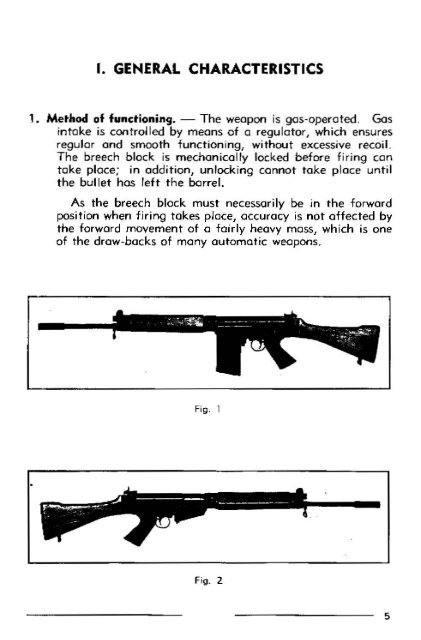
I. GENERAL CHARACTERISTICS<br />
1. Method of functioning. The weapon is gos-operoted. Gas<br />
intake is controlled by means of a regulator, which ensures<br />
regular and smooth functioning, without excessjve recoil.<br />
The breech block is mechanically locked before fi ri ng can<br />
take place; in addition, unlocking cannot take place until<br />
the bul let has left t he barrel.<br />
•<br />
As the breech block must necessarily be in the forward<br />
position when firing takes pJace, accuracy is not affected by<br />
the forward movement of a fairly heavy mass, which is one<br />
of the draw-backs of many automatic weapoos.<br />
Fi g. 1<br />
Fig. 2<br />
5
- As the piston (P} moves backwards, it contacts the slide (B)<br />
(fig. 5), thrusting it to the rear.<br />
- The p iston spring, which has been compressed by the rear<br />
movement of the piston, relaxes and returns the piston to its<br />
forward position.<br />
L----------------------- --.,<br />
Fig. 5<br />
2 . REAR MOVEMENT OF THE MECHANISM<br />
a . Unlocking the breech<br />
As the slide moves backwards, the romps of the slide (B 1)<br />
engage the cams of the breech block (C 1) {fig. 6), raising the<br />
rear end of the breech block and lifting it out of engagement<br />
with jts locking shoulder (D) in the body (E) (fig. 1).<br />
- The breech block is thus unlocked.<br />
10--------------------<br />
Fig. 6<br />
'<br />
@<br />
' •<br />
@ E<br />
b. Extraction<br />
I<br />
L ---------.-.-----<br />
Fig. 7<br />
- The shoulders of the slide ( 82) engage those of the breech<br />
block (C2) (fig. 8) and the slide ond breech block travel to<br />
the rear together.<br />
During this movement, the extractor dow withdraws the<br />
spent case rearwards from the chamber, holding it in t he<br />
breech block recess.<br />
c. Ejection<br />
I<br />
I<br />
L----------<br />
Fig. 8<br />
- When the breech block recess is a I most ci. t the some I eve I as<br />
the rear face of the ejection opening, the spent case contacts<br />
--------------------1t
V. ZEROING<br />
The rifle is zeroed before isSIJe to the user, but it may<br />
perhaps need some adjustment to -correct elevation and d irection,<br />
to individual requirements.<br />
Zeroing must be carried out by a qualified armourer, who<br />
wi II have the spec ia I type tools for moving the foresight and<br />
spare fares i ghts, if required.<br />
I. Correction for elevation<br />
Errors in elevation ore corrected by screwing the foresight<br />
up or down. If it is screwed up, the M.P.I. (Mean point of<br />
impact) wi II be moved down and vice versa.<br />
The spring and retaining catch locate and hold the foresight<br />
in position; this forms a c li cking device with the outer circu_mference<br />
of t he foresight 1 which is serrated into 16 divisions, wh1ch<br />
assists the armourer when calcuJating movement of the M.P. I.<br />
One d ivision {or click) is equal to a variation in M.P.I. of<br />
1 em at 1 00 metres.<br />
2. Correction for direction<br />
Errors in direction ore corrected by moving the backsight<br />
to the right or left.<br />
r f the M.P.I. is to the right, the screw on the left of the<br />
bocksight is slightly loosened, and the screw on the right i_s<br />
screwed up, thus moving the sight laterally along its dovetail<br />
from right to left. Tighten the screw on the left.<br />
When the cor-rection has been made and before shootjng<br />
commences, tighten both bocks i ght screws.<br />
If the M .P .I. is to the jeft 1 the bocksight is moved similarly,<br />
but from left to right.<br />
Moving the backsight screws 1 divis1on (or click) is equal<br />
to o variation in M.P. I. of 1 em at 100 metres.<br />
26-----------------------------------------<br />
VI. IMMEDIATE ACTION AND STOPPAGES<br />
1 . Immediate action<br />
If the rifle foi Is to function when fired, there is a "stop-<br />
/1<br />
page .<br />
A mechanical stoppage, other than that caused by an empty<br />
magazine, can often be corrected by taking immediate actiOT'I<br />
without investigating its cause.<br />
2. Procedure for immediate action<br />
Operation 1. Remove the magazine.<br />
Operation 2. Pu II the cocking handle fuJI y to the rear so that<br />
a defective or- wrongly positioned round can be cleared from<br />
the mechoni sm.<br />
Operation 3. Release the cocking handle to aJiow the mechanism<br />
to move forward.<br />
Operation 4. Replace the magazine.<br />
Operation 5. Recock the weapon then reI ease the cocking<br />
handle, so that a new round is fed into the chamber.<br />
Operation 6. Resume firing.<br />
If the stoppage recurs, find out the cause.<br />
3. Stoppages<br />
Regular cleaning and correct maintenance will ensure thot<br />
stoppages with this rifle ore very rare. Their chief cause is<br />
insufficient gas, which may be due to ·incorrect setting of the<br />
gas regulator/ fouling of p iston head or gas plug, or some obstruction<br />
fouling the mechanis:-n. The following tabu,ation indicates<br />
types of stoppages, their causes and remedies.<br />
----------------------27
32-----------------<br />
F>g. 3 1<br />
Fog_ 32<br />
Operot•on 5. Put the grenade on the launcher and ensure that<br />
it is fully nome.<br />
Operot•on 6. Release the safety from the nile and finally the<br />
grenade safety should be removed. The rille is then ready<br />
to fire.<br />
II the L.A.R. has not been supplied with the special gas<br />
plug with grenade sight, this must first be fitted.<br />
To do this, proceed os follows:<br />
o) Remove the existing gos cylinder plug (chapter IX-1-e).<br />
b) Replace it by o plug w1th grenade s•gnt:<br />
Insert the plug by pressing down the p•ston spring, w•tn the<br />
notched end of the ox•s for the sight leaf turned towards the<br />
barrel and exerting pressure on it to make the axis rise onto<br />
Flg, 33<br />
the collar of the barrel, in front of the front sling swivel<br />
(fig 33).<br />
Push the plug fully home, then turn the sight-plug assembly<br />
o quarter of o turn clockw•se.<br />
Turn the sight down to the rear ogo1nst the foresight block.<br />
-----------------33
N. B. - Firing grenade without sighting, or at 45o, con be<br />
done with the standard gas plug, provided this is turned through<br />
1800 so thot the letters "Gr" appear uppermost, instead of the<br />
letter 0 A"_<br />
5. Firing po$ilion<br />
a) Direct fire (fig. 34)<br />
For the three usual positions (standing, kneeling, prone) the<br />
method of holding the rifle is identical.<br />
Grasp the middle of the hondguord firmly with the left hand.<br />
f-!old the pistol grip firmly with the right hand, with the index<br />
longer secured in front of the trigger.<br />
34--------<br />
- Hold the butt under the right armpit, never leon it on the<br />
shoulder.<br />
b) Indirect fire (fig. 35)<br />
Dig the heel of the butt into the earth, with the pistol grip<br />
uppermost, i.e. towards the firer.<br />
Incline the weapon at the required angle.<br />
Hold the foot down on the toe of the butt to prevent it from<br />
moving its position.<br />
c) Note<br />
Fig. 35<br />
So for as possible ovoid placing the butt on ony hard surface,<br />
such os concrete, rock, etc. This is particularly important far<br />
indirect fire and firing from the prone posttion, when the soldier<br />
naturally tends to anchor the toe of the butt, to ovoid the jerk<br />
of recoil.<br />
-----------------35
I. FIELD STRIPPING<br />
The soldoer should know each step In loeld stroppong so well<br />
thot he con do it on the dark. No tools ore needed, but ot moy<br />
be necessary to use the nose of a bullet.<br />
- Remove the magazine.<br />
Cock the mechonosm to make sure there is no cartridge left<br />
in the chamber, let the mechanism go forward and put the<br />
rolfe at sole, the hammer remaining in the cocked posotion.<br />
o ) Strippin9 the mechanism<br />
Press the tngger frame-body lock lever, on the left side of<br />
the trigger frame, fully upwards; hold the barrel group<br />
firmly and press the butt-trigger group downwards, swinging<br />
the rifle open like o shotgun (see fig. 36).<br />
•0-----------------<br />
F;g 36<br />
Remove the slide-breech block assembly by grasping the slide<br />
rod, hinged to the slide {fig. 37).<br />
Foq 31<br />
b) Ta remove the cover from the body, slode ot to the reor<br />
(fog. 38).<br />
F;g. 38<br />
---------------41
The carrying handle consists of the handle oxls, handle, rwo<br />
assembly washers and two spring washers (fig. 54), securing the<br />
handle to its axis.<br />
48-----------------<br />
0 0 I • - • - • • 0 0<br />
Fig. 54<br />
5. GAS REGULATOR SLEEVE AND GAS CYLINDER<br />
Remove the p;ston (see group of operotoons I).<br />
Remove the hondguard /see group of opetotions 3).<br />
o} Gas regulator slec"e<br />
Using the spanner, completely unscrew the regulator sleeve<br />
(fig. 55) and pull it to the rear to keep ot free of Its spring.<br />
Use a screwdriver to release the sprong from the two spring<br />
seatongs recessed in the gas block /fig. 56).<br />
Fig. 55<br />
-------------------49
Withdraw the spring to the rear (fig. 57).<br />
b Gas cylinder<br />
fl!l. 57<br />
Usong the spanner, completely unscrew the gas cylinder<br />
bush (fog. 58) ond move it forward.<br />
Remove the gos cylonder retooning pon (fog. 591 .<br />
Fig 58 Fog, 59<br />
so--------<br />
Unscrew the gos cylonder and withdraw It to the rear<br />
(fig 60).<br />
Fig. 60<br />
Wothdrow the gos tube nut and the gos regulator sleeve<br />
(fig.61)<br />
•<br />
Fiq. 61<br />
---------------51
8. JOINT PIN, TRIGGER FRAME-BODY<br />
Field stnp the weapon 'group of operotoons I ).<br />
Swing the ri fie open os for os it will go. Unscrew the<br />
retainer pon of the jomt pm, usong o coon oro screwdnver (fig 68).<br />
fog 68 f og , 69<br />
Remove the retooner pin (fig. 69).<br />
54-------------------<br />
Insert the nose ot o cartridge In the centre recess of the<br />
joint pon ond push. The joont pon wdl then be pushed out obout<br />
1 em (fJg. 70).<br />
Fog 70<br />
Remove the joont pon (ftg 71) .<br />
Fog 7 1<br />
----------55
W1th the JOin t pin removed, the butt-tngger group 1S seporoted<br />
from the body-borrel group (f1g. 72).<br />
so-----------------<br />
Fog. 12<br />
9. SAFETY SEAR<br />
F1eld stnp the weopon (group of operations I).<br />
Stnp the JOint pin frome-body (group of operot1ons 8).<br />
Rotote the safety sear opprox. 9()o pull•ng it gently to the<br />
reor (f1g. 73) unt1l it is cleor of the body.<br />
N. B.--The $eOr spring is riveted ond should not be stripped.<br />
Flg. 13<br />
---------------57
Fog. 75<br />
10. COCKING HANDLE<br />
Field strip the weapon (group of operottons I).<br />
Using a pon drift, remove the lug retoonong pon (fig 74).<br />
Remove the lug (fig. 75). If thos os rather toght, use a pin<br />
drift to push ot out, from the onside of the rifle outwards<br />
5&----------------<br />
Pull the cocking handle slide to ots rear posotoon, then exert<br />
a backwards pull on the handle and, at the same time, depress<br />
the lug of the cockong handle slide with a pon droit, or the slide<br />
rod (fig. 76). untol the cocking handle moves freely to the rear.<br />
ng. 76<br />
Withdraw the handle completely towards the rear (fog. 77).<br />
Fig, 77<br />
----------------59
N. B. - If the handguard has already been stropped (group<br />
of operations 3), after remav.ng the cocking handle knob Hog. 74<br />
and 75), ot os only necessary to pull rhe handle forward to remove<br />
(fig. 78)<br />
fig. 78<br />
Using o pon drift, push out the detent retaonong pon (fig 79)<br />
60-----------------<br />
F;g. 19<br />
The cockong handle detent ond its spring are then freed<br />
(fig. 80).<br />
I<br />
I<br />
---------------61
) Holding open device. - Grosp the hold•ng open dev•c:e<br />
ond remove from 1ts hous1ng (f•g 85).<br />
64-----------------<br />
Foo 85<br />
IZ. LOCKING SHOULDER<br />
Field strip the nfle (group of operot•ons I)<br />
Push the lock•ng shoulder outwards from left to right, using<br />
o drift (fig. 86).<br />
N. B. - The locking shoulder is only removed when rhe<br />
heodspoce needs to be adjusted.<br />
Fog 86<br />
Withdrew the lock•ng shoulder (fig. 87)<br />
Fig 87<br />
---------65
Use the nose of a cartridge to push out the hammer axis pin<br />
(fig, 96).<br />
Remove hammer pin and hammer (f1g. 97)<br />
70--------<br />
Fig. 97<br />
c) Seor.- Use the nose of o cartridge to push the sear axis<br />
pin out of its housing (fig. 98).<br />
Hold the sear WIth the left hand to prevent it from flying out<br />
under the action of its spring and pull out the axis pin (fig. 99).<br />
Fig, 99<br />
---- ------------ 71
Use a larger screwdriver to unscrew the pistol grip nut screw<br />
(fig. 1 04).<br />
Remove the screw and pistol grip (fig. 105).<br />
Fig. 104<br />
F•g. I 05<br />
f) Trigger guard. - Remove the trigger guard by rotating<br />
it forward, while pulling it slightly downward (fig. 106).<br />
74--------------<br />
Fig. I 06<br />
g) Tri.gger spring. -- W oth finger press the trigger plunger<br />
to the rear (this will compress the trigger spring) and rotate it<br />
downwards (fig. 107).<br />
F!Q. I 07<br />
This releases the trigger plunger and trigger spring (fig. 108).<br />
Fig. 108<br />
------------------ 75
14. REAR SLING SWIVEL b) Butt plate.- Unscrew butt plate screw (frg. 112).<br />
AND SUTT PLATE<br />
o) ReoJ sling swiv-el. - Unscrew both screws retarning the.<br />
plate for rear sling swivel (fig. 1 09L<br />
This releases the plo fe end the rear sling swivel (fig. 110).<br />
J '<br />
fig. 109<br />
76-----------------<br />
fro. I I I<br />
Push out the retorning<br />
pin secunng the sling swivel<br />
·and separate the bose of t he<br />
swivel with the sling swivel<br />
(fig. 111).<br />
f 1g. liZ<br />
Remove the butt plate (fig. 1 13) and the spread washer for<br />
the butt plate screw.<br />
Fog. 113<br />
-----------------77<br />
•
Press on the bocksoght catch and worhdrow this forward<br />
(fig. 126), after rcmovmg the bocksight stop pon<br />
FoQ. 126<br />
This frees the bncksoght catch and ors spr.ng, os well as the<br />
spring stop for odrusrong screws (fig 1271.<br />
I<br />
84------------------<br />
T<br />
• 1<br />
Ft; 121<br />
18. MAGAZINE<br />
Use the nose of o cartridge, to dosengoge the bottom plate<br />
(fig. 128). Then knock t he mogozone ogaonsr a piece of wood,<br />
as Illustrated, unto! the bottom plate comes out about half on<br />
inch (fog. 129).<br />
-<br />
Fig, 128<br />
-----------------85
Remove the magazine bottom plate, taking core to hold the<br />
sprong down with the thumb (fig. 130).<br />
Fig. 130<br />
Remove the platform spring up to its lost spiral (fig. 13 1).<br />
86-----------------<br />
Ftg. 131<br />
Acting on the spring, turn the magazine platform opprox.<br />
45o inside the magazine, then extract rhe platform (fig. 132).<br />
Disengage the spring from the two rear and one front retaining<br />
lugs.<br />
fig. 132<br />
--------87


