No Hassle Guarantee - Galls
No Hassle Guarantee - Galls
No Hassle Guarantee - Galls

Create successful ePaper yourself
Turn your PDF publications into a flip-book with our unique Google optimized e-Paper software.
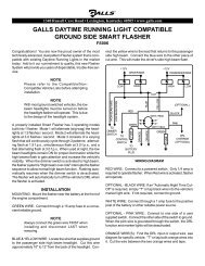
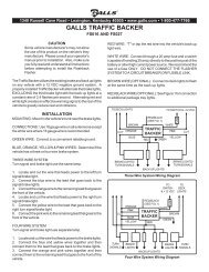
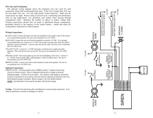
Wire Size and Termination<br />
The adjacent wiring diagram shows the minimum wire size used for each<br />
connection, along with recommended lead color. If the wire is longer than 10 ft. use<br />
the next larger wire size. Use only high quality crimp connectors. Make sure all<br />
connections are tight. Route wiring to prevent wear, overheating and interference<br />
with air bag deployment. Use grommets and sealant when passing through<br />
compartment walls. Minimize the number of splices to reduce voltage drop.<br />
Ground connections should only be made to substantial chassis components,<br />
preferably directly to the negative of the vehicle battery. Install and check all<br />
wiring before connection to vehicle battery.<br />
Wiring Connections:<br />
BLACK LEAD: Connect the black wire from the amplifier to the negative side of the battery<br />
or to a good chassis ground. Be sure to use minimum size #16 AWG.<br />
RED LEAD: Connect the red wire from the amplifier to positive 12 VDC. It is strongly<br />
recommended that you connect to a 12 VDC source that is present only when the vehicle<br />
ignition is in the on position. A power relay may also be used. Be sure to use a minimum<br />
size #16 AWG wire.<br />
YELLOW LEAD: Connect to +12VDC through a switched power supply (possibly<br />
ignition). This will turn the siren on and off. Be sure to use minimum size #18 AWG<br />
wire.<br />
ORANGE LEAD: This lead supplies power for the backlighting of the siren. Connect it<br />
to +12VDC from the dash lights, parking lights or other switched source. Be sure to<br />
use minimum size #18 AWG wire.<br />
BROWN LEADS: Connect one lead to each terminal or lead of the speaker. Be sure to<br />
use minimum size #16 AWG wire.<br />
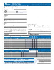
Optional Connections:<br />
GREEN LEAD: Used for remote (Aux.) HORN control. Connect to horn ring<br />
circuit or remote switch. Siren is shipped with positive voltage activation<br />
defaulted (apply +12VDC for activation). For vehicles with negative activation<br />
(connect to ground for activation), the unit must be opened up and have the Aux.<br />
Horn polarity jumper switched. Refer to pages 3 & 4 for further details.<br />
NOTE: Cut lead short if not used & insulate with electrical tape.<br />
Testing - Test all siren functions after installation to assure proper operation. Test<br />
vehicle operation to assure no damage to vehicle.<br />
Negative<br />
Switching AUX<br />
Horn Jumper<br />
Selected<br />
-5- -6-<br />
+12 VDC<br />
+12 VDC<br />
VEHICLE<br />
HORN<br />
Horn<br />
Switch/Relay<br />
VEHICLE<br />
HORN<br />
Horn<br />
Switch/Relay<br />
ON/OFF Power Switch for Siren<br />
(Possibly Connected to Ignition)<br />
+12 VDC<br />
OR<br />
Positive<br />
Switching AUX<br />
Horn Jumper<br />
Selected<br />
Backlighting Switch (Connect to<br />
Dash Lights, Parking Lights, Etc.)<br />
+12 VDC<br />
SPEAKER<br />
11 OHMS<br />
+<br />
12 - Brown (#14 AWG)<br />
11 - Yellow (#18 AWG)<br />
10 - Green (#18 AWG)<br />
9 - Orange (#18 AWG)<br />
8 - <strong>No</strong> Connection<br />
7 - Brown (#14 AWG)<br />
6 - <strong>No</strong> Connection<br />
5 - <strong>No</strong> Connection<br />
4 - <strong>No</strong> Connection<br />
3 - <strong>No</strong> Connection<br />
2 - Black (#14 AWG)<br />
1 - Red (#14 AWG)<br />
SIREN<br />
BATTERY<br />
+