No Hassle Guarantee - Galls
No Hassle Guarantee - Galls
No Hassle Guarantee - Galls

Create successful ePaper yourself
Turn your PDF publications into a flip-book with our unique Google optimized e-Paper software.
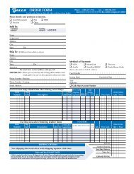
<strong>No</strong> <strong>Hassle</strong> <strong>Guarantee</strong><br />
Providing quality products to professionals who<br />
protect and serve the public is our core purpose.<br />
If you aren’t satisfied with a newly purchased item, simply return<br />
it to us so we can repair it, replace it or refund your money.<br />
To Return Merchandise…<br />
You don't need to call us if you have a problem with the<br />
merchandise you've received. Simply follow the instructions on<br />
the reverse side of the packing slip that comes with your order.<br />
<strong>Galls</strong> provides a preaddressed label for you to affix to the<br />
package. If you don't have your packing slip, place the item in<br />
the original packaging (along with a brief explanation for the<br />
return), then place in a second box to prevent damage. To assure<br />
speedy handling, please ship it directly to:<br />
<strong>Galls</strong>, Inc. Returns Department<br />
1340 Russell Cave Road, Lexington, KY 40505<br />
If you have any questions concerning this or any other <strong>Galls</strong> product, please contact<br />
our Customer Service Department at (800) 477-7766.<br />
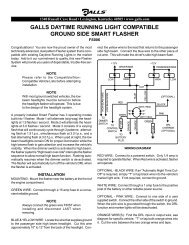
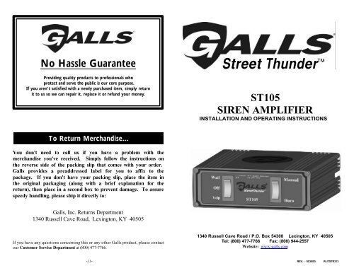
Street Thunder<br />
ST105<br />
SIREN AMPLIFIER<br />
INSTALLATION AND OPERATING INSTRUCTIONS<br />
1340 Russell Cave Road / P.O. Box 54308 Lexington, KY 40505<br />
Tel: (800) 477-7766 Fax: (800) 944-2557<br />
Website: www.galls.com<br />
-11- REV. - 10/30/03 PLITSTR313
INSTALLATION INFORMATION MODEL: ST105___<br />
SERIAL NO: OPTIONS<br />
PURCHASE DATE: _____ Thunder Disabled<br />
DEALER: _____ Two-Tone Enabled<br />
INSTALLATION DATE: _____ Negative Aux. Polarity<br />
INSTALLER:<br />
Model and serial number located on the top of the amplifier unit<br />
TABLE OF CONTENTS<br />
GENERAL DESCRIPTION 1<br />
INSTALLATION 2-6<br />
UNPACKING 2<br />
INSTALLER-SELECTABLE OPTIONS 2-3<br />
MOUNTING 4<br />
ELECTRICAL CONNECTIONS 4-6<br />
AMPLIFIER 4<br />
WIRING 5<br />
WIRING DIAGRAM 6<br />
OPERATION 7-8<br />
MANUAL 7<br />
HORN 7<br />
AUXILIARY INPUT 8<br />
SERVICE 9-11<br />
TROUBLESHOOTING 9<br />
SPECIFICATIONS 10<br />
LIMITED WARRANTY 10<br />
RETURNS 11<br />
NOTICE<br />
Due to continuous product improvements, we must reserve the right to change any specifications and information<br />
contained in this manual at any time without notice. <strong>Galls</strong> makes no warranty of any kind with regard to this manual,<br />
including, but not limited to, the implied warranties of merchantability and fitness for a particular purpose. <strong>Galls</strong><br />
shall not be liable for errors contained herein or for incidental or consequential damages in connection with the<br />
furnishing, performance, or use of this manual.<br />
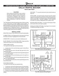
GENERAL DESCRIPTION<br />
The ST105 Remote Siren Amplifier is designed for single 100W speaker use. It<br />
comes standard with the amplifier unit and control head (switch panel) all in one<br />
unit. The primary operating modes are Wail, Yelp, Standby, Manual, and Horn.<br />
Both the Horn and the Manual Control function will override all other functions,<br />
and can be utilized at any time via a rocker switch. The Thunder function can be<br />
optionally disabled entirely with a program jumper.<br />
The siren amplifier has been designed with several protection features to provide<br />
exceptional field service. Excessively high voltage detection will disable the siren<br />
output to protect both the amplifier and the speaker. Fused inputs provide safety<br />
against reverse polarity. Speaker protection shuts down the output if the speaker<br />
output becomes electrically shorted. CAUTION: These protection features will<br />
not guard against overloading the outputs.<br />
SPECIFICATIONS<br />
Input Voltage 10 - 16 VDC (negative ground)<br />
Input Current 8 Amps @ 13.6 VDC (100W speaker)<br />
Standby Current Less than 20 mA<br />
Output Power 105 WATTS RMS MAX. (15.0 VDC - single 100W speaker)<br />
Siren Frequency 675Hz - 1633Hz<br />
High Voltage Protection 16 - 18 VDC will cause siren output to cease, resume at normal<br />
Short Circuit Current 50 AMPS (supply circuit must be capable of supplying this)<br />
Operating Temperature -15° F to +140°F<br />
Controls 3-position primary mode rocker switch (Wail, Yelp, and Standby)<br />
Momentary 3-position rocker switch (Horn and Manual)<br />
Thunder disable (jumper programmable)<br />
Two-Tone Enable (jumper programmable)<br />
Connections<br />
(12-Pin Connector)<br />
Auxiliary Horn Polarity (jumper programmable)<br />
-1- -10-<br />
Detachable, 12-pin, positive locking connector with pigtail leads<br />
(1) Positive, (1) Negative, (2) Speaker, (1) Power Control,<br />
(1) Backlighting and (1) auxiliary Horn.<br />
Size 2” High, 6” Wide, 5-3/4” Deep<br />
Boxed Weight ST105 - 3.4 lbs.<br />
LIMITED WARRANTY<br />
<strong>Galls</strong> warrants this new product to be free from defects in material and<br />
workmanship, under normal use and service, for a period of seven (7) years from<br />
the date of delivery to the first user-purchaser.<br />
During this warranty period the obligation of <strong>Galls</strong> is limited to repairing or<br />
replacing, as <strong>Galls</strong> may elect, any part or parts of such product which after<br />
examination by <strong>Galls</strong> is determined to be defective in material and/or workmanship.<br />
This warranty does not cover labor charges for removal or re-installation of the<br />
product. Fuses and lamps are not covered under this warranty.<br />
This warranty does not extend to any unit that has been subjected to abuse,<br />
misuse, improper installation or which has not been adequately maintained, nor to<br />
units which have problems related to service or modification at any facility other<br />
than the manufacturer.<br />
THERE ARE NO OTHER WARRANTIES, EXPRESSED OR IMPLIED,<br />
INCLUDING BUT NOT LIMITED TO, ANY IMPLIED WARRANTIES OF<br />
MERCHANTABILITY OR FITNESS FOR A PARTICULAR PURPOSE. IN NO<br />
EVENT SHALL GALLS BE LIABLE FOR ANY LOSS OF PROFITS OR ANY<br />
INDIRECT OR CONSEQUENTIAL DAMAGES ARISING OUT OF ANY SUCH<br />
DEFECT IN MATERIALS OR WORKMANSHIP.
TROUBLESHOOTING<br />
Symptom Possible Cause Check<br />
<strong>No</strong> power Power source not turned on<br />
Connector loose<br />
Amplifier 15A fuse blown<br />
Is ignition switch in AUX or ON position?<br />
Do you hear a “pop” when turned on?<br />
Is power hooked up backwards? Positive<br />
ground vehicle?<br />
Is an external fuse or circuit breaker used?<br />
Are the negative leads connected to a good<br />
ground?<br />
Input voltage must be less than 16 volts.<br />
Check for a short or an open in the output.<br />
Is the speaker bell or tip loose?<br />
Is the Aux. Input used and wired properly?<br />
<strong>No</strong> siren<br />
Loose connection at power<br />
source<br />
High voltage protection<br />
tone Bad speaker or speaker wiring<br />
Distorted Speaker assembly loose<br />
siren sound Intermittent Aux. Input<br />
connection<br />
High vehicle voltage<br />
Input voltage must be less than 16 volts.<br />
Intermittent High voltage protection Is the vehicle voltage regulator working<br />
siren tone<br />
properly?<br />
Circuit breaker in supply Is a circuit breaker used with at least a 30A<br />
rating?<br />
Bad Connection<br />
Is the connector tight on the back of the<br />
unit?<br />
Shorted speaker or speaker wire Does the speaker have water damage, or is<br />
a wire pinched?<br />
Horn Horn switch stuck<br />
Does the horn switch return fully when<br />
function or<br />
released?<br />
Manual Manual push-button switch Does the Manual push-button switch return<br />
function stuck<br />
fully when released?<br />
stuck on<br />
Aux. Input improperly<br />
Is the AUX Input used and wired properly?<br />
connected<br />
Is the AUX horn wire wired for correct<br />
Aux. Horn Input Polarity<br />
reversed<br />
polarity?<br />
Wrong Two-Tone option jumper Is the TT jumper option properly<br />
siren tone installed<br />
configured?<br />
Aux. Horn Input Polarity Is the AUX horn wire wired for correct<br />
reversed<br />
polarity?<br />
Thunder not Thunder disabled Is the TD jumper option configured<br />
working<br />
properly?<br />
INSTALLATION<br />
Proper installation of the unit is essential for years of safe, reliable operation.<br />
Please read all instructions before installing the unit. Failure to follow these<br />
instructions can cause serious damage to the unit or vehicle and may void<br />
warranties.<br />
Qualifications<br />
The installer must have a firm knowledge of basic electricity, vehicle electrical<br />
systems and emergency equipment.<br />
Keep These Instructions<br />
Keep these instructions in the vehicle or other safe place for future reference.<br />
Advise the vehicle operator of the location.<br />
Unpacking<br />
Inspect contents for shipping damage. If any damage is found, alert the carrier<br />
immediately. ST105 contents should include: an amplifier box with wiring<br />
pigtail, a "U" bracket for mounting, and these instructions. Please contact <strong>Galls</strong><br />
immediately if any components are missing.<br />
INSTALLER-SELECTABLE OPTIONS<br />
The ST105 has Thunder disable, Two-Tone enable, and Auxiliary Horn Polarity<br />
options that can be selected during installation. An internal jumper on the printed<br />
circuit board inside the amplifier case allows the installer to select these options.<br />
These options should be set before installation of the unit.<br />
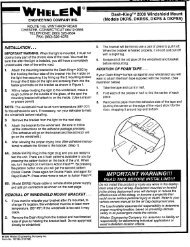
Amplifier Cover Removal<br />
Remove the four Philip<br />
head screws located on the<br />
back of the amplifier unit.<br />
Carefully slide the cover off<br />
of the extrusion.<br />
-9- -2-
INSTALLER-SELECTABLE OPTIONS (cont'inued)<br />
Thunder Disable - The Thunder function can be completely disabled by moving<br />
one of the option jumpers inside the amplifier unit from "Extra" to the "TD". When<br />
Thunder is disabled, the Manual button will not have any effect on the tone while<br />
the siren is in the Yelp mode<br />
Two-Tone Enable - The Two-Tone function can be enabled by moving one of the<br />
option jumpers inside the amplifier unit from "Extra" to the "Two-Tone". When<br />
Two-Tone is enabled, a European Two-Tone sound will replace the Thunder sound<br />
when the Manual button is pressed while the siren is in the Yelp mode. (The tone<br />
will toggle between Yelp and Two-Tone each time the Manual button is pressed)<br />
Auxiliary Horn Polarity - The Auxiliary Input allows activation by an external<br />
source of the Horn function. This input is usually wired into the vehicle horn<br />
switch. The wiring diagram on page 6 shows two connection examples. NOTE:<br />
Permanent disconnection of the vehicle horn is NOT recommended.<br />
The auxiliary input is normally activated by applying a positive voltage to the wire.<br />
To activate by connecting to ground (negative), move the "AUX" option jumper<br />
from the "Pos." pins to the "Neg." pins. (See diagram above).<br />
Selector Switch<br />
Position:<br />
SIREN OUTPUT:<br />
Speaker<br />
Output<br />
-3- -8-<br />
Pressing Manual Pushbutton<br />
Wail Wail Yelp<br />
Yelp Yelp Thunder (or Two-Tone)<br />
(Remains Yelp if Thunder disabled)<br />
OFF <strong>No</strong> Output Creates a manual WAIL tone while<br />
button is being held that sweeps down<br />
when the button is released.<br />
(NOTE: THUNDER may be optionally disabled via program jumpers. See<br />
INSTALLER-SELECTABLE OPTIONS on pages 2 & 3).<br />
(NOTE: TWO-TONE may be optionally selected over Thunder via program<br />
jumpers. See INSTALLER-SELECTABLE OPTIONS on pages 2 & 3).<br />
AUXILIARY INPUT<br />
During installation an auxiliary input may be connected to the vehicle horn ring or<br />
other switching device. It provides the same operation as pressing the Horn button.<br />
See wiring diagram on page 6 for wiring details.
OPERATION<br />
GENERAL<br />
This unit is designed for easy operation under the stress associated with highspeed<br />
pursuit. Most siren functions are accessible with one simple motion without<br />
repetitive activation of switches or automatic timed switching that can interfere with<br />
desired operation.<br />
SELECTOR SWITCH<br />
The three-position rocker switch on the left controls the primary operating<br />
function of the siren.<br />
WAIL - A normal rise-fall tone used on highways and areas with low traffic<br />
or constant traffic flow.<br />
YELP - A rapid warble tone used in light to moderately congested areas.<br />
OFF - (Manual/Standby) - A silent mode that allows push-button Horn and<br />
push-button Manual (MAN). The siren output winds down when the<br />
Manual push-button switch is released.<br />
Manual<br />
With the left selector switch in the OFF position, the Manual side of the<br />
momentary switch provides a manually activated Wail siren tone. While the<br />
selector switch is in the Wail or Yelp position, this switch provides a generally<br />
quicker changing tone. (See table on next page). These quicker tones are used to<br />
momentarily alert motorists at intersections and very highly congested areas.<br />
Pressing the button once changes to the next faster tone. Pressing the Manual<br />
button again will toggle the siren back to the original tone.<br />
Optional configuration allows disabling of the Thunder tone entirely. This option<br />
is selected during installation and may be governed by State or Local laws.<br />
(Refer to the INSTALLER SELECTABLE OPTIONS section on pages 2 & 3).<br />
Horn<br />
This momentary push-button switch provides a simulated air-horn tone while<br />
pressed. This can be used to either replace, or to supplement the normal<br />
vehicle horn and is useful at intersections or in low noise areas. This tone will<br />
override all other siren tones.<br />
MOUNTING<br />
SAFETY PRECAUTIONS<br />
For the safety of the installer, vehicle operator, passengers and the community<br />
please observe the following safety precautions. Failure to follow all safety<br />
precautions and instructions may result in property damage, injury or death.<br />
!!! WARNING !!!<br />
DO NOT mount in air bag deployment area.<br />
Devices should be mounted only in locations listed in SAE standard J1849.<br />
Controls should be placed within convenient reach of the driver.<br />
Assure clearances before drilling in vehicle.<br />
Sound levels produced by attached speakers can cause permanent hearing loss.<br />
Never operate this unit without adequate hearing protection for you and<br />
others in the area. (OSHA 1910.95)<br />
AMPLIFIER<br />
The ST105 siren may be mounted above the dash, below the dash, on a<br />
tunnel, or in a rack with the mounting u-bracket provided. Choose a<br />
mounting location convenient to the operator and away from any air bag<br />
deployment areas. Inspect behind mounting area for clearance. Assure<br />
adequate ventilation to prevent overheating. Consider wire routing and<br />
access to connections. Install mounting bracket to vehicle using 1/4"<br />
hardware (not supplied).<br />
ELECTRICAL CONNECTIONS<br />
-- 15 --<br />
15 Amp Fuse Power Connector<br />
AMPLIFIER<br />
Electrical power connections to the amplifier are made using a removable<br />
connector located on the back of the amplifier case. You should make all electrical<br />
connections to the power connector before installing the connector on the unit. If<br />
the unit needs service, the power connector can be easily removed without unwiring<br />
the connector.<br />
The power supply of the unit must be capable of delivering peak currents up to<br />
30 amps for adequate short circuit protection and reliable operation. The preferred<br />
source is directly at the vehicle battery. The unit is internally fused. A wiring<br />
diagram on page 6 shows detail of how to wire the power connector on the amplifier<br />
to the vehicle.<br />
-7- -4-
Wire Size and Termination<br />
The adjacent wiring diagram shows the minimum wire size used for each<br />
connection, along with recommended lead color. If the wire is longer than 10 ft. use<br />
the next larger wire size. Use only high quality crimp connectors. Make sure all<br />
connections are tight. Route wiring to prevent wear, overheating and interference<br />
with air bag deployment. Use grommets and sealant when passing through<br />
compartment walls. Minimize the number of splices to reduce voltage drop.<br />
Ground connections should only be made to substantial chassis components,<br />
preferably directly to the negative of the vehicle battery. Install and check all<br />
wiring before connection to vehicle battery.<br />
Wiring Connections:<br />
BLACK LEAD: Connect the black wire from the amplifier to the negative side of the battery<br />
or to a good chassis ground. Be sure to use minimum size #16 AWG.<br />
RED LEAD: Connect the red wire from the amplifier to positive 12 VDC. It is strongly<br />
recommended that you connect to a 12 VDC source that is present only when the vehicle<br />
ignition is in the on position. A power relay may also be used. Be sure to use a minimum<br />
size #16 AWG wire.<br />
YELLOW LEAD: Connect to +12VDC through a switched power supply (possibly<br />
ignition). This will turn the siren on and off. Be sure to use minimum size #18 AWG<br />
wire.<br />
ORANGE LEAD: This lead supplies power for the backlighting of the siren. Connect it<br />
to +12VDC from the dash lights, parking lights or other switched source. Be sure to<br />
use minimum size #18 AWG wire.<br />
BROWN LEADS: Connect one lead to each terminal or lead of the speaker. Be sure to<br />
use minimum size #16 AWG wire.<br />
Optional Connections:<br />
GREEN LEAD: Used for remote (Aux.) HORN control. Connect to horn ring<br />
circuit or remote switch. Siren is shipped with positive voltage activation<br />
defaulted (apply +12VDC for activation). For vehicles with negative activation<br />
(connect to ground for activation), the unit must be opened up and have the Aux.<br />
Horn polarity jumper switched. Refer to pages 3 & 4 for further details.<br />
NOTE: Cut lead short if not used & insulate with electrical tape.<br />
Testing - Test all siren functions after installation to assure proper operation. Test<br />
vehicle operation to assure no damage to vehicle.<br />
Negative<br />
Switching AUX<br />
Horn Jumper<br />
Selected<br />
-5- -6-<br />
+12 VDC<br />
+12 VDC<br />
VEHICLE<br />
HORN<br />
Horn<br />
Switch/Relay<br />
VEHICLE<br />
HORN<br />
Horn<br />
Switch/Relay<br />
ON/OFF Power Switch for Siren<br />
(Possibly Connected to Ignition)<br />
+12 VDC<br />
OR<br />
Positive<br />
Switching AUX<br />
Horn Jumper<br />
Selected<br />
Backlighting Switch (Connect to<br />
Dash Lights, Parking Lights, Etc.)<br />
+12 VDC<br />
SPEAKER<br />
11 OHMS<br />
+<br />
12 - Brown (#14 AWG)<br />
11 - Yellow (#18 AWG)<br />
10 - Green (#18 AWG)<br />
9 - Orange (#18 AWG)<br />
8 - <strong>No</strong> Connection<br />
7 - Brown (#14 AWG)<br />
6 - <strong>No</strong> Connection<br />
5 - <strong>No</strong> Connection<br />
4 - <strong>No</strong> Connection<br />
3 - <strong>No</strong> Connection<br />
2 - Black (#14 AWG)<br />
1 - Red (#14 AWG)<br />
SIREN<br />
BATTERY<br />
+