Installation Instructions - Airmar Technology Corporation
Installation Instructions - Airmar Technology Corporation
Installation Instructions - Airmar Technology Corporation

Create successful ePaper yourself
Turn your PDF publications into a flip-book with our unique Google optimized e-Paper software.
17-395-01 rev. 04 09/06<br />
Retractable Thru-hull<br />
Depth & Temperature Transducer<br />
Models: DT800, DT800V<br />
U.S. Patents: 4,898,029; Re-issue 33, 982; 6,904,798 B2.<br />
Australian Patent 605,281.Canadian Patent 1,313,775. Japanese Patent 1851014<br />
IMPORTANT:<br />
Please read the instructions completely<br />
before proceeding with the installation. These<br />
instructions supersede any other instructions in your<br />
instrument manual if they differ.<br />
CAUTION:<br />
NEVER USE SOLVENTS!<br />
Cleaners, fuel, paint, sealants, and other products may<br />
contain strong solvents, such as acetone, which attack<br />
many plastics greatly reducing their strength.<br />
Applications<br />
• Plastic housing recommended for fiberglass or metal hulls only.<br />
Never install a plastic housing in a wood hull since swelling of<br />
the wood can possibly fracture the plastic.<br />
• Bronze housing recommended for fiberglass or wood hulls.<br />
Never mount a bronze housing in an aluminum hull because<br />
electrolytic corrosion will occur.<br />
• Stainless steel housing compatible with all hull materials.<br />
Recommended for aluminum hulls to prevent electrolytic corrosion<br />
provided the stainless steel housing is isolated from the metal hull.<br />
• Never install a metal housing in a vessel with a positive ground<br />
system.<br />
Tools & Materials<br />
OWNER’S GUIDE &<br />
Water-based antifouling paint ( MANDATORY IN SALT WATER)<br />
Safety goggles<br />
Dust mask<br />
Electric drill with 10mm (3/8") or larger chuck capacity<br />
Drill bit: 3mm or 1/8"<br />
Hole saw: 51mm or 2" (plastic or bronze housing)<br />
57mm or 2-1/4" (stainless steel housing in a metal hull)<br />
Countersink tool (installing a flush housing)<br />
Sandpaper<br />
Mild household detergent or weak solvent (such as alcohol)<br />
File (installation in a metal hull)<br />
Marine sealant (suitable for below waterline)<br />
Additional washer [for aluminum hull less than 6mm (1/4") thick]<br />
Slip-joint pliers (installing a bronze housing)<br />
Zip-ties<br />
<strong>Installation</strong> in a cored fiberglass hull (see page 3):<br />
Hole saw for hull interior: 60mm or 2-3/8"<br />
Fiberglass cloth and resin<br />
or Cylinder, wax, tape, and casting epoxy<br />
INSTALLATION INSTRUCTIONS<br />
Record the information found on the cable tag for future reference.<br />
Part No._________________Date___________Frequency________kHz<br />
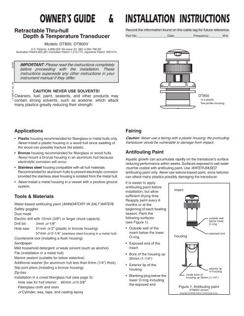
Fairing<br />
Caution:<br />
Never use a fairing with a plastic housing; the protruding<br />
transducer would be vulnerable to damage from impact.<br />
Antifouling Paint<br />
DT800<br />
in a plastic<br />
low-profile<br />
housing<br />
Aquatic growth can accumulate rapidly on the transducer’s surface<br />
reducing performance within weeks. Surfaces exposed to salt water<br />
must be coated with antifouling paint. Use WATER-BASED<br />
antifouling paint only. Never use ketone-based paint, since ketones<br />
can attack many plastics possibly damaging the transducer.<br />
It is easier to apply<br />
antifouling paint before<br />
installation, but allow<br />
sufficient drying time.<br />
Reapply paint every 6<br />
months or at the<br />
beginning of each boating<br />
season. Paint the<br />
insert<br />
following surfaces<br />
outside wall<br />
(see Figure 1):<br />
• Outside wall of the<br />
below lower<br />
O-ring<br />
insert below the lower<br />
O-ring<br />
• Exposed end of the<br />
insert<br />
• Bore of the housing up<br />
30mm (1-1/4")<br />
• Exterior lip of the<br />
housing<br />
exposed end<br />
housing<br />
exterior lip<br />
of housing<br />
• Blanking plug below the<br />
lower O-ring including<br />
inside bore of<br />
housing up 30mm (1-1/4")<br />
the exposed end<br />
Figure 1. Antifouling paint<br />
DT800V shown<br />
Copyright © 2006 <strong>Airmar</strong> <strong>Technology</strong> Corp.
Mounting Location<br />
• The water flowing across the hull must be smooth with a<br />
minimum of bubbles and turbulence (especially at high speeds).<br />
Caution:<br />
DO NOT MOUNT near water intake or discharge<br />
openings, or behind strakes, fittings, or hull irregularities.<br />
• The transducer must be continuously immersed in water.<br />
• The transducer beam must be unobstructed by the keel or<br />
propeller shaft(s).<br />
• Choose a location away from interference caused by power and<br />
radiation sources such as: the propeller(s) and shaft(s), other<br />
machinery, other echosounders, and other cables. The lower<br />
the noise level, the higher the echosounder gain setting that<br />
can be used.<br />
• Choose a location with a deadrise angle of 20º or less, so the<br />
transducer beam will be aimed at the bottom.<br />
• Choose an accessible spot inside the vessel with adequate<br />
headroom for the height of the housing, tightening the nuts, and<br />
removing the insert. Allow a minimum of 280mm (11").<br />
2<br />
large displacement hulls small displacement hulls<br />
outboard and I/O<br />
fin keel sailboats<br />
Figure 2.<br />
plastic housing<br />
planing hulls<br />
full keel sailboats<br />
Best location for transducer<br />
Copyright © 2005 <strong>Airmar</strong> <strong>Technology</strong> Corp.<br />
stepped hull<br />
insert<br />
cap nut<br />
(plastic)<br />
housing<br />
safety wire<br />
hull nut<br />
washer<br />
hull<br />
Hull Types (see Figure 2)<br />
• Displacement hull powerboats—Locate<br />
amidships near the<br />
centerline. The starboard side of the hull where the propeller<br />
blades are moving downward is preferred.<br />
• Planing hull powerboats—Mount<br />
well aft, on or near the<br />
centerline, and well inboard of the first set of lifting strakes to insure<br />
that the transducer will be in contact with the water at high speeds.<br />
The starboard side of the hull where the propeller blades are<br />
moving downward is preferred.<br />
Outboard and I/O—Mount<br />
just forward of the engine(s).<br />
Inboard—Mount<br />
well ahead of the propeller(s) and shaft(s).<br />
Stepped hull—Mount<br />
just ahead of the first step.<br />
Boat capable of speeds above 25kn (29MPH)—Review the<br />
installation location and operating results of similar boats before<br />
proceeding.<br />
• Fin keel sailboats—Mount<br />
on or as close as possible to the<br />
centerline and forward of the fin keel 300–600mm (1–2').<br />
• Full keel sailboats—Locate<br />
amidships and away from the keel<br />
at the point of minimum deadrise.<br />
<strong>Installation</strong><br />
Cored fiberglass hull—Follow<br />
separate instructions on page 3.<br />
Hole Drilling<br />
Warning:<br />
Always wear safety goggles and a dust mask.<br />
1. Drill a 3mm or 1/8" pilot hole from inside the hull. If there is a rib,<br />
strut or other hull irregularity near the selected mounting<br />
location, drill from the outside.<br />
2. Using the appropriate size hole saw, cut a hole from outside the hull.<br />
Flush housing—Use<br />
a countersink tool to create a seat in the hull.<br />
3. Sand and clean the area around the hole, inside and outside, to<br />
ensure that the sealant will adhere properly to the hull. If there is any<br />
petroleum residue inside the hull, remove it with either mild<br />
household detergent or a weak solvent (alcohol) before sanding.<br />
Metal hull—Remove<br />
all burrs with a file and sandpaper.<br />
Bedding<br />
metal housing in non-metal<br />
hull<br />
Caution:<br />
A stainless steel housing must be isolated from a metal<br />
hull to prevent electrolytic corrosion.<br />
Apply a 2mm (1/16") thick layer of marine sealant around the lip of<br />
the housing that contacts the hull and up the sidewall of the<br />
housing (see Figure 3). The sealant must extend 6mm (1/4")<br />
higher than the combined thickness of the hull, the washer(s), and<br />
BOW ➤<br />
stainless steel housing in metal hull<br />
cap nut<br />
(plastic)<br />
safety wire<br />
housing<br />
hull nut<br />
washer<br />
hull (metal)<br />
isolation<br />
ring<br />
marine sealant on lip<br />
and sidewall of housing<br />
marine sealant on lip<br />
and sidewall of housing<br />
Figure 3. Bedding and installing— DT800V shown<br />
Copyright © 2005 <strong>Airmar</strong> <strong>Technology</strong> Corp.<br />
marine sealant on lip and<br />
sidewall of housing<br />
and isolation ring where it contacts hull<br />
insert
the hull nut. This will ensure there is sealant in the threads to seal<br />
the hull and to hold the hull nut securely in place.<br />
Stainless steel housing in a metal hull—To<br />
isolate the stainless<br />
steel housing from the metal hull, slide the isolation ring onto the<br />
housing. Apply additional sealant to the surfaces of the ring that<br />
will contact the hull, filling any cavities in and around the ring.<br />
Installing<br />
Caution:<br />
Never pull, carry, or hold the transducer by the cable as<br />
this may sever internal connections.<br />
1. From outside the hull, push the housing into the mounting hole<br />
using a twisting motion to squeeze out excess marine sealant<br />
(see Figure 3). Align the arrow on the lip of the housing to point<br />
forward toward the bow.<br />
2. From inside the hull, slide the washer onto the housing.<br />
Aluminum hull less than 6mm ( 1/4" ) thick—Use<br />
an<br />
additional rubbery, fiberglass, or plastic washer. Never use<br />
bronze since electrolytic corrosion will occur. Never use wood<br />
since it will swell, possibly fracturing the plastic housing.<br />
Warning:<br />
Stainless steel housing in a metal hull only—Be<br />
sure the washer contacts the hull. Do not tighten the hull nut<br />
with the washer against the isolation ring, as the housing will<br />
not be firmly installed. If necessary, sand the isolation ring until<br />
the washer rests against the hull.<br />
3. Screw the hull nut in place being sure the arrow on the rim of<br />
the housing is still positioned forward toward the bow.<br />
Plastic housing—<br />
Do not clamp tightly on the wrenching flats<br />
possibly causing the housing to fracture.<br />
Plastic hull nut—<br />
HAND-TIGHTEN only. Do not over-tighten.<br />
Metal hull nut—Tighten<br />
with slip-joint pliers.<br />
Cored Fiberglass Hull—<br />
Do not over-tighten, crushing the hull.<br />
Wood hull—Allow<br />
the wood to swell before tightening the nut.<br />
4. Remove any excess marine sealant on the outside of the hull to<br />
ensure smooth water flow over the transducer.<br />
Warning: The O-rings must be intact and well lubricated to<br />
make a watertight seal.<br />
5. After the marine sealant cures, inspect the O-rings on the insert<br />
(replace if necessary) and lubricate them with the silicone<br />
lubricant supplied.<br />
Warning:<br />
Be sure the insert is fully inserted into the housing,<br />
and the cap nut is screwed on completely.<br />
6. Slide the insert into the housing with any arrow on the top<br />
pointing in the direction indicated. Screw the cap nut several<br />
turns until the threads are engaged. Continue to tighten the cap<br />
nut. HAND-TIGHTEN only. Do not over tighten. Be careful not<br />
to rotate the housing and disturb the sealant.<br />
Warning:<br />
Always attach the safety wire to prevent the insert<br />
from backing out in the unlikely event that the cap nut fails or is<br />
screwed on incorrectly.<br />
7. Attach the safety wire.<br />
Plastic housing—Attach<br />
the safety wire to one eye in the hull<br />
nut. Keeping the wire taut throughout, lead the wire in a<br />
counterclockwise direction and thread it through one eye in the<br />
cap nut. Thread the wire through the eye a second time. Then<br />
lead the wire through the eye in the insert. Twist the wire<br />
securely to itself.<br />
Metal housing—Wrap<br />
one end of the safety wire tightly around<br />
the housing and twist it together with the long end. Keeping the<br />
wire taut throughout, lead the wire straight up and through one<br />
eye in the cap nut. Thread the wire through the eye a second<br />
time. Then lead the wire counterclockwise and through the eye<br />
in the insert. Twist the wire securely to itself.<br />
Caution:<br />
If your transducer came with a connector, do not<br />
remove it to ease cable routing. If the cable must be cut and<br />
spliced, use <strong>Airmar</strong>’s splash-proof Junction Box No. 33-035 and<br />
follow the instructions provided. Cutting the cable or removing<br />
the waterproof connector, except when using <strong>Airmar</strong>’s junction<br />
box, will void the transducer warranty.<br />
8. Route the cable to the instrument being careful not to tear the<br />
cable jacket when passing it through the bulkhead(s) and other<br />
parts of the boat. To reduce electrical interference, separate the<br />
transducer cable from other electrical wiring and the engine.<br />
Coil any excess cable and secure it in place with zip-ties to<br />
prevent damage.<br />
9. Refer to the instrument owner’s manual to connect the<br />
transducer to the instrument.<br />
<strong>Installation</strong> in a Cored Fiberglass Hull<br />
The core (wood or foam) must be cut and sealed carefully. The<br />
core must be protected from water seepage, and the hull must be<br />
reinforced to prevent it from crushing under the hull nut allowing<br />
the housing to become loose.<br />
Warning:<br />
Always wear safety goggles and a dust mask.<br />
1. Drill a 3mm or 1/8" pilot hole from inside the hull. If there is a rib,<br />
strut, or other hull irregularity near the selected mounting location,<br />
drill from the outside. (If the hole is drilled in the wrong location,<br />
drill a second hole in a better location. Apply masking tape to the<br />
outside of the hull over the incorrect hole and fill it with epoxy.)<br />
2. Using a 51mm or 2" hole saw, cut the hole from outside the hull<br />
through the outer skin only (see Figure 4).<br />
3. From inside the hull, use a 60mm or 2-3/8" hole saw to cut<br />
through the inner skin and most of the core. The core material<br />
can be very soft. Apply only light pressure to the hole saw after<br />
cutting through the inner skin to avoid accidentally cutting the<br />
outer skin.<br />
4. Remove the plug of core material so the inside of the outer skin<br />
and the inner core of the hull are fully exposed. Sand and clean<br />
the inner skin, core, and the outer skin around the hole.<br />
Caution:<br />
Completely seal the hull to prevent water seepage<br />
into the core.<br />
5. If you are skilled with fiberglass, saturate a layer of fiberglass<br />
cloth with a suitable resin and lay it inside the hole to seal and<br />
strengthen the core. Add layers until the hole is the correct<br />
diameter.<br />
Alternatively, a hollow or solid cylinder of the correct diameter<br />
can be coated with wax and taped in place. Fill the gap between<br />
the cylinder and hull with casting epoxy. After the epoxy has set,<br />
remove the cylinder.<br />
pour in<br />
casting<br />
epoxy<br />
hull thickness<br />
solid or hollow cylinder<br />
9-12 mm<br />
(3/8-1/2")<br />
larger than the<br />
hole through the<br />
hull’s outer skin<br />
Figure 4. Preparing a cored fiberglass hull<br />
Copyright © 2005 <strong>Airmar</strong> <strong>Technology</strong> Corp.<br />
inner skin<br />
core<br />
outer skin<br />
3
6. Sand and clean the area around the hole, inside and outside, to<br />
ensure that the sealant will adhere properly to the hull. If there is<br />
any petroleum residue inside the hull, remove it with either mild<br />
household detergent or a weak solvent (alcohol) before sanding.<br />
7. Proceed with “Bedding” and “Installing” (see pages 2 and 3).<br />
Checking for Leaks<br />
Warning: DO NOT leave the boat in the water unchecked for<br />
several days.<br />
When the boat is placed in the water, immediately check the<br />
thru-hull transducer for leaks. Note that very small leaks may not<br />
be readily observed. Do not to leave the boat in the water for more<br />
than 3 hours before checking it again. If there is a small leak,<br />
there may be considerable bilge water accumulation after 24<br />
hours. If a leak is observed, repeat “Bedding” and “Installing”<br />
immediately (see pages 2 and 3).<br />
Operation & Maintenance<br />
DT800V only—How the Valve Works<br />
WARNING: THE VALVE IS NOT A WATERTIGHT SEAL!<br />
Always use the insert or the blanking plug secured with the<br />
safety wire for a watertight seal.<br />
The DT800V incorporates a self-closing valve which minimizes<br />
the flow of water into the boat when the insert is removed. The<br />
curved flap valve is activated by both a spring and water pressure.<br />
Water pushes the flap valve upward to block the opening, so there<br />
is no gush of water into the boat.<br />
Using the Blanking Plug<br />
To protect the insert, use the blanking plug:<br />
• When the boat will be kept in salt water for more than a week.<br />
• When the boat will be removed from the water.<br />
• When aquatic growth buildup is suspected due to inaccurate<br />
readings from the instrument.<br />
4<br />
Warning: The O-rings must be intact and well lubricated to<br />
make a watertight seal.<br />
1. On the blanking plug, inspect the O-rings (replace if necessary)<br />
and lubricate them with the silicone lubricant supplied or<br />
petroleum jelly (Vaseline®) (see Figure 5).<br />
2. Remove the insert from the housing by removing the safety wire<br />
and unscrewing the cap nut (see Figure 3). This will jack out<br />
the insert.<br />
DT800—With the blanking plug ready in one hand, pull the<br />
insert most of the way out. Remove the insert and rapidly<br />
replace it with the blanking plug. With practice, only 250ml<br />
(10oz.) of water will enter the boat.<br />
DT800V—Grasp the insert and remove it with a slow pulling<br />
motion. Slide the blanking plug into the housing.<br />
Note: In the very unlikely event that the valve breaks, replace<br />
the housing the next time the boat is hauled.<br />
Warning: Be sure the blanking plug is fully inserted into the<br />
housing, and the cap nut is screwed on completely.<br />
3. Screw the cap nut several turns until the threads are engaged.<br />
Continue to tighten the cap nut. HAND-TIGHTEN only.<br />
Do not over-tighten.<br />
AIRMAR ®<br />
TECHNOLOGY CORPORATION<br />
insert<br />
WARNING: Always attach the safety wire to prevent the<br />
blanking plug from backing out in the unlikely event that the<br />
insert nut and/or cap nut fails or is screwed on incorrectly.<br />
4. Reattach the safety wire.<br />
Servicing the Insert<br />
Aquatic growth can accumulate rapidly on the transducer’s<br />
surface reducing performance within weeks. Clean the insert with<br />
a Scotch-Brite® scour pad and mild household detergent, being<br />
careful to avoid scratching the depth transducer. If fouling is<br />
severe, lightly wet sand it with fine grade wet/dry paper.<br />
O-rings must be free of abrasions and cuts to ensure a watertight<br />
seal. Install two O-rings near the bottom of the insert<br />
(see Figure 5). Place the remaining two O-rings in similar<br />
positions on the blanking plug.<br />
Winterizing<br />
After the boat has been hauled for winter storage, remove the<br />
blanking plug to let the water drain away before reinserting it. This<br />
will prevent any water from freezing around the blanking plug and<br />
possibly cracking it.<br />
Replacement Parts<br />
Lost, broken, or worn parts should be replace immediately. Obtain<br />
parts from your instrument manufacturer or marine dealer.<br />
Gemeco (USA) Tel: 843.394.3565<br />
Fax: 843.394.3736<br />
email: sales@gemeco.com<br />
<strong>Airmar</strong> Europe Tel: +45.45.81.04.18<br />
Fax: +45.45.81.04.93<br />
email: sales@airmareurope.com<br />
If you have purchased a plastic housing and have a wood hull or<br />
desire greater strength, purchase an <strong>Airmar</strong> metal housing.<br />
Hull Nut or<br />
Isolation Ring<br />
04-004 (plastic)<br />
02-030 (bronze)<br />
02-570-01 (stainless steel)<br />
04-186-1 (isolation ring)<br />
Housing, Nut & Washer<br />
NO VALVE<br />
33-100 (bronze, low profile, B17)<br />
33-224-01 (bronze, counterbore, B21)<br />
33-091-01 (bronze, flush, B119)<br />
33-495-01 (stainless steel, low profile, SS577)<br />
O-rings 33-519-01<br />
Blanking Plug 33-538-01<br />
Housing with Valve, Nut & Washer 33-510-01 (plastic, low profile, P617)<br />
Transducer Replacement—The information needed to order a<br />
replacement <strong>Airmar</strong> multisensor is printed on the cable tag. Do<br />
not remove this tag. When ordering, specify the part number,<br />
date, and frequency in kHz. For convenient reference, record this<br />
information on the top of page one.<br />
35 Meadowbrook Drive, Milford, New Hampshire 03055-4613, USA<br />
■ www.airmar.com<br />
Copyright © 2003, 2005, 2006 <strong>Airmar</strong> <strong>Technology</strong> Corp. All rights reserved.<br />
small<br />
O-ring(s)<br />
Figure 5. Replacing the O-rings<br />
Copyright © 2005 <strong>Airmar</strong> <strong>Technology</strong> Corp.<br />
blanking plug