Overview of changes made to TZtouch with ver 3.01 ... - Furuno USA
Overview of changes made to TZtouch with ver 3.01 ... - Furuno USA
Overview of changes made to TZtouch with ver 3.01 ... - Furuno USA

You also want an ePaper? Increase the reach of your titles
YUMPU automatically turns print PDFs into web optimized ePapers that Google loves.
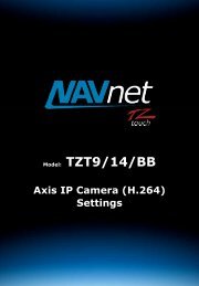
Model: TZT9/14/BB<br />
S<strong>of</strong>tware v<strong>3.01</strong><br />
1
1. Tighter Integration<br />
1-1. High Resolution by TruEcho CHIRP – Model<br />
DFF1-UHD<br />
1-2. Audio Control by FUSION-Link – Fusion<br />
MS700 series<br />
1-3. Au<strong>to</strong>pilot Control by TZT9/14/BB – Model<br />
NavPilot 700<br />
1-4. Radar Echoes on TZT9/14/BB – Model<br />
FAR2xx7<br />
1-5. Fish Echoes on TZT9/14/BB – Model<br />
FCV1150<br />
1-6. Compatible <strong>with</strong> H.264 Format – Axis<br />
Camera<br />
2. Improved User Interface and Visual Presentation<br />
2-1. Refined Undo/Redo Icons (TZT9/14 Only)<br />
2-2. Zoom In/Out <strong>with</strong> Slider Bar on Preview<br />
Windows<br />
2-3. Plotter Range Box on the Right for More Data<br />
Box Space (TZT14 Only)<br />
2-4. External Touch Screen Mode (TZT14 Only)<br />
2-4. Indicating Wireless LAN Status Update<br />
INDEX<br />
3. Radar<br />
3-1. 2 nd Guard Zone<br />
3-2. 2 nd Blank Sec<strong>to</strong>r<br />
4. Fish Finder<br />
4-1. Switching HF/LF Layout by Tap<br />
5. Weather & Tide<br />
5-1. Weather Data Shared between Displays<br />
through Ethernet<br />
6-2. SST Color Scale<br />
6. Axis Camera<br />
6-1. Axis IP Camera <strong>with</strong> H.264 Format<br />
6-2. Axis Video Ser<strong>ver</strong> <strong>with</strong> H.264 Format<br />
7. Data Box<br />
7-1. Newly Available Data – TTA and DTA<br />
8. Points and Routes – NavNet 3D<br />
8-1. Transferring Points and Routes <strong>to</strong> NavNet 3D<br />
8-2. Optimized Active Route Synchronization<br />
<strong>with</strong> NavNet 3D<br />
9. v<strong>3.01</strong> – Common S<strong>of</strong>tware Version<br />
2
1. Tighter Integration<br />
TZ<strong>to</strong>uch v<strong>3.01</strong> s<strong>of</strong>tware expands the networks capabilities through tighter integration <strong>with</strong> existing sensors.<br />
1-1. High Resolution by TruEcho CHIRP – Model DFF1-UHD<br />
The DFF1-UHD (coming soon) provides high-resolution echoes when<br />
connected <strong>to</strong> a TZ<strong>to</strong>uch network, running v<strong>3.01</strong> s<strong>of</strong>tware.<br />
Note: NavNet 3D <strong>ver</strong>sion v2.11 s<strong>of</strong>tware, currently under development, will provide compatibility <strong>with</strong> the DFF1-UHD.<br />
1-2. Audio Control by FUSION-Link – Fusion MS700 series<br />
The MS700 series Fusion audio system can be networked <strong>with</strong> TZ<strong>to</strong>uch<br />
via Ethernet for audio controls from the TZT9/14/BB MFD.<br />
The MS700 series is an audio system produced by Fusion Electronics, New Zealand. This series provides a feature called<br />
FUSION-Link, which allows MFD’s <strong>to</strong> control the MS700 system. FUSION-Link supports both NMEA2000 and Ethernet<br />
pro<strong>to</strong>cols; howe<strong>ver</strong> TZ<strong>to</strong>uch uses only the Ethernet network <strong>to</strong> interface <strong>with</strong> the MS700 for FUSION-Link. NavNet<br />
TZ<strong>to</strong>uch v<strong>3.01</strong> does not support an NMEA2000 connection <strong>with</strong> Fusion. For additional details on Fusion Electronics, visit<br />
their Website at .<br />
3
1-3. Au<strong>to</strong>pilot Control by TZT9/14/BB – Model NavPilot 700<br />
TZ<strong>to</strong>uch v<strong>3.01</strong> provides au<strong>to</strong>pilot control when the NavPilot 700 is<br />
connected (NavPilot s<strong>of</strong>tware update required – coming soon). In the<br />
data box, the NavPilot 700 control window is available <strong>to</strong> activate AUTO<br />
and NAV modes and adjust a course.<br />
Note: The NavPilot 700 control windows in the data box change according <strong>to</strong> the status <strong>of</strong> the au<strong>to</strong>pilot.<br />
Standby AUTO Mode NAV Mode<br />
Tap [Au<strong>to</strong>] <strong>to</strong> activate the AUTO<br />
mode. If a route is activated, the<br />
[Nav] icon is also available: Tap<br />
[Nav] <strong>to</strong> activate the NAV mode.<br />
When the NavPilot 700 is in AUTO<br />
mode, the window design <strong>changes</strong> <strong>to</strong><br />
this.<br />
When the NavPilot 700 is in NAV<br />
mode, the window design <strong>changes</strong> <strong>to</strong><br />
this, and the next waypoint name<br />
appears at the bot<strong>to</strong>m.<br />
Note: (1) To control the NavPilot 700 using the TZT9/14/BB v<strong>3.01</strong>, the NavPilot 700 s<strong>of</strong>tware will require a future<br />
s<strong>of</strong>tware update, which will be introduced in the coming months.<br />
(2) The NavPilot 700 full system, including the dedicated control unit (FAP7001/7011), is always necessary, as shown in<br />
the following diagram.<br />
4
(3) The NavPilot 700 control window is currently only available when the TZ<strong>to</strong>uch MFD is in Demo mode.<br />
1-4. Radar Echoes on TZT9/14/BB – Model FAR2xx7<br />
The FAR2xx7 is selectable as a Radar source, when connected <strong>to</strong> the network via Ethernet. Echoes from the FAR2xx7 can<br />
be displayed on the TZ<strong>to</strong>uch MFD. Available functions and limitations are the same as those found in NavNet 3D.<br />
1-5. Fish Echoes on TZT9/14/BB – Model FCV1150<br />
The FCV1150, when connected via Ethernet, is now selectable as a Fish Finder source. Echoes from the FCV1150 can be<br />
displayed on the TZ<strong>to</strong>uch MFD. Available functions and limitations are the same as those found in NavNet 3D.<br />
1-6. Compatible <strong>with</strong> H.264 Format – Axis Camera<br />
In addition <strong>to</strong> MPEG-4 format, v<strong>3.01</strong> s<strong>of</strong>tware is compatible <strong>with</strong> the latest H.264 format. See Section<br />
6 for more information.<br />
5
2. Improved User Interface and Visual Presentation<br />
2-1. Refined Undo/Redo Icons (TZT9/14 Only)<br />
The Undo/Redo icons have been redesigned. Note:<br />
the TZTBB has had these designs since launch.<br />
v<strong>3.01</strong> v2.01/2.01<br />
2-2. Zoom In/Out <strong>with</strong> Slider Bar on Preview Windows<br />
Screenshot<br />
The Plotter, Radar and Weather preview windows can be<br />
zoomed in/out <strong>with</strong> a slider bar. Tap the preview window <strong>to</strong><br />
show the slider bar, then slide it <strong>to</strong> zoom in/out.<br />
2-3. Plotter Range Box on the Right for More Data Box Space (TZT14 Only)<br />
The TZT14 displays the Plotter range box on the right. This layout is effective especially when Radar o<strong>ver</strong>lay and depth<br />
shading functions are activated. Compared <strong>to</strong> v2.01, a larger space is now available for data boxes, as shown in the<br />
following screenshots. Note: the TZTBB has had this design since its introduction.<br />
6
TZT14 v<strong>3.01</strong> / TZTBB v2.01 TZT14 v2.01 or earlier<br />
The range box is on the bot<strong>to</strong>m right. The range box is on the bot<strong>to</strong>m left.<br />
In Radar o<strong>ver</strong>lay mode, only the Radar range box is on the<br />
bot<strong>to</strong>m left. There is no impact on the data box space.<br />
In the Radar o<strong>ver</strong>lay and Depth Shading modes, both the<br />
Radar range box and depth shading indica<strong>to</strong>r are on the<br />
bot<strong>to</strong>m left. The data box space is reduced, but it is still<br />
larger than v2.01.<br />
Both the Plotter and Radar range boxes are on the left. In<br />
this example, one <strong>of</strong> the data boxes is not available in<br />
v2.01, due <strong>to</strong> the reduced space.<br />
E<strong>ver</strong>ything is on the bot<strong>to</strong>m left, and the data box space is<br />
more limited. In this example, the Highway mode box is<br />
unavailable, due <strong>to</strong> the reduced space.<br />
7
Note: The TZT9 <strong>with</strong> v<strong>3.01</strong> s<strong>of</strong>tware has no change in the<br />
Plotter range box layout, due <strong>to</strong> the limited space in split<br />
screen mode. To increase the data box space, use the 2 nd data<br />
box, which is available on the right side <strong>of</strong> the screen.<br />
2-4. External Touch Screen Mode (TZT14 Only)<br />
With TZ<strong>to</strong>uch v<strong>3.01</strong> s<strong>of</strong>tware, you can now operate a TZT14 MFD using an external multi <strong>to</strong>uch moni<strong>to</strong>r. With v2.01 or<br />
earlier s<strong>of</strong>tware, operation was limited due <strong>to</strong> the lack <strong>of</strong> a [Home] but<strong>to</strong>n. The latest s<strong>of</strong>tware update <strong>of</strong>fers optimized<br />
multi <strong>to</strong>uch user interface for full <strong>to</strong>uch control, similar <strong>to</strong> the TZTBB, when in External Touch Screen mode.<br />
8
Setting External Touch Screen Mode on TZT14<br />
Menu Descriptions<br />
Access [Menu] – [Initial Setup]:<br />
[External Touch Screen Mode] – [ON] (Default – [OFF])<br />
[Show Home But<strong>to</strong>n] – [ON] (Default – [OFF])<br />
The [Show Home But<strong>to</strong>n] setting inserts a virtual home key on the<br />
<strong>to</strong>p right <strong>of</strong> the TZT14 screen.<br />
When these settings are applied, the TZT14 display mode <strong>changes</strong> and<br />
the same images are now displayed on the external <strong>to</strong>uch screen<br />
moni<strong>to</strong>r. As shown below, the context menu appears at a tapped spot,<br />
a slider bar is available for zooming in/out, and a virtual home key icon<br />
appears at the <strong>to</strong>p right <strong>of</strong> the screen. These <strong>changes</strong> are the same as<br />
those found in the TZTBB user interface.<br />
Note: The External Touch Screen Mode is not available on the TZT9. This<br />
is because the TZT9 resolution (800x480) is <strong>to</strong>o small for this mode,<br />
especially in split screen view. In [Menu] – [Initial Setup], there is no<br />
option for [External Touch Screen Mode] or [Show Home But<strong>to</strong>n],<br />
as shown at left.<br />
9
Tips – TZTBB<br />
By default, the TZTBB always launches in External Touch Screen Mode,<br />
allowing for full <strong>to</strong>uch screen operation. As <strong>with</strong> the TZT9, in [Menu] –<br />
[Initial Setup], there is no option for [External Touch Screen Mode]<br />
or [Show Home But<strong>to</strong>n].<br />
Tips – TZT14 <strong>with</strong>out External Touch Screen<br />
If you prefer the context menu <strong>to</strong> show at tapped spots on the TZT14,<br />
even when no external <strong>to</strong>uch screen is connected, you can set [Show<br />
Home But<strong>to</strong>n] <strong>to</strong> [OFF] and turn [External Touch Screen Mode] <strong>to</strong><br />
[ON]. You can access the [Home] function using the hardware Home key.<br />
2-4. Indicating Wireless LAN Status Update<br />
In [Menu] – [Wireless LAN Settings], it can take se<strong>ver</strong>al<br />
seconds <strong>to</strong> update the Wireless LAN setting status when turning<br />
this function [ON] or [OFF]. With v2.01/2.02 or earlier<br />
s<strong>of</strong>tware, it was possible <strong>to</strong> tap [ON/OFF] frequently while the<br />
status was updating. With v<strong>3.01</strong>, once you tap the [ON/OFF]<br />
but<strong>to</strong>n, a message pops up, encouraging you <strong>to</strong> wait for the<br />
status <strong>to</strong> finish updating.<br />
10
3. Radar<br />
The guard zone and blank sec<strong>to</strong>r options are expanded as follows.<br />
3-1. 2 nd Guard Zone<br />
Setting Screenshot<br />
Tap the screen and select [Guard Zone 2] from the context menu.<br />
3-2. 2 nd Blank Sec<strong>to</strong>r<br />
Menu Settings Screenshot<br />
In [Menu] – [Radar] – [Radar Initial Setup] – [Enable Sec<strong>to</strong>r 2<br />
Blanking], adjust angles <strong>to</strong> set the 2 nd blank sec<strong>to</strong>r.<br />
11
4. Fish Finder<br />
4-1. Switching HF/LF Layout by Tap<br />
In the dual frequency screen mode, the layout <strong>of</strong> HF/LF can be switched by tapping the range/depth box, according <strong>to</strong><br />
your preference.<br />
5. Weather & Tide<br />
HF / LF LF / HF<br />
5-1. Weather Data Shared between Displays through Ethernet<br />
With v2.01/2.02 or earlier s<strong>of</strong>tware, <strong>to</strong> show weather information on multiple TZ<strong>to</strong>uch MFDs in the network, it was<br />
necessary <strong>to</strong> download weather data through the Internet or load it from an SD card on each MFD. With v<strong>3.01</strong>, once<br />
weather data is loaded on<strong>to</strong> one MFD, the other units in the network share the data.<br />
12
6-2. SST Color Scale<br />
You can manually adjust the temperature range <strong>to</strong> be<br />
o<strong>ver</strong>laid on the screen <strong>with</strong> the same user interface as<br />
Depth Shading: Tap the color scale bar <strong>to</strong> show a slider bar,<br />
and slide it up and down <strong>to</strong> select the color scale.<br />
In the example above, there are two TZT14 units in the<br />
network. TZT14 No. 1 (Range 1,062 nm) and TZT14 No.<br />
2 (Range: 3,021 nm). Weather data has been loaded on<br />
<strong>to</strong> TZT14 No. 1 through the Internet from an SD card.<br />
TZT14 No. 2 then receives the same data through the<br />
network via Ethernet. Howe<strong>ver</strong>, due <strong>to</strong> the larger range<br />
scale <strong>of</strong> the chart on TZT14 No. 2, the shared weather<br />
data is shown in the center <strong>of</strong> the screen, as highlighted<br />
at left.<br />
When SST (Sea Surface Temperature) information is shown,<br />
the following SST color scale bar is available on the left<br />
bot<strong>to</strong>m <strong>of</strong> the screen.<br />
13
6. Axis Camera<br />
6-1. Axis IP Camera <strong>with</strong> H.264 Format<br />
In addition <strong>to</strong> MPEG-4, v<strong>3.01</strong> s<strong>of</strong>tware is also compatible <strong>with</strong> H.264 format, which <strong>of</strong>fers a wider selection <strong>of</strong> cameras<br />
from Axis Communications AB.<br />
Note:<br />
(1) MPEG-4 compatible Axis cameras, which were compatible <strong>with</strong> TZ<strong>to</strong>uch v2.01 s<strong>of</strong>tware (or earlier), continue <strong>to</strong> work<br />
<strong>with</strong> v<strong>3.01</strong>. For MPEG-4 cameras, you should continue following conventional set-up procedures.<br />
(2) Native H.264 formatted images occupy a great amount <strong>of</strong> bandwidth for the TZ<strong>to</strong>uch Ethernet network. In addition<br />
<strong>to</strong> conventional settings, such as IP address, be sure <strong>to</strong> set the [Resolution] <strong>to</strong> [800x600 (4:3)] pixels or less and<br />
[Compression] level <strong>to</strong> [30].<br />
Latest Axis Cameras Compatible <strong>with</strong> H.264 Format<br />
To find the latest Axis camera models <strong>with</strong> the H.264 format, visit the Axis product selec<strong>to</strong>r on their website:<br />
. There are many more H.264 options than MPEG-4.<br />
14
6-2. Axis Video Ser<strong>ver</strong> <strong>with</strong> H.264 Format<br />
With v2.01/2.02 s<strong>of</strong>tware, compatible Axis video ser<strong>ver</strong>s were limited <strong>to</strong> the AXIS241S/Q for MPEG-4 format. The<br />
v<strong>3.01</strong>’s compatibility <strong>with</strong> H.264 format removes this limitation, and the latest Axis video ser<strong>ver</strong>s can be used. The menu<br />
for Axis video services has been renamed <strong>to</strong> “Axis Quad Ser<strong>ver</strong>.”<br />
v<strong>3.01</strong> v2.01/2.02<br />
The menu has been renamed <strong>to</strong> “Axis Quad Ser<strong>ver</strong>” <strong>to</strong><br />
indicate a 4-analog-input model.<br />
The previous menu, “241Q” specified the compatible Axis<br />
video ser<strong>ver</strong> for MPEG-4 format.<br />
Tested Axis Video Ser<strong>ver</strong>s at <strong>Furuno</strong> Electric Company<br />
The following Axis video ser<strong>ver</strong>s were used for tests at <strong>Furuno</strong> Electric Company, in Japan.<br />
M7014<br />
http://www.axis.com/products/cam_m7014/index.htm<br />
Analog Input: Four (4) channels<br />
Ethernet Output: One (1) channel<br />
P7214<br />
http://www.axis.com/products/cam_p7214/index.htm<br />
Analog Input: Four (4) channels<br />
Ethernet Output: One (1) channel<br />
Tips – 4 x IP Cameras and 2 x Video Ser<strong>ver</strong>s<br />
As Axis IP camera and video ser<strong>ver</strong> sources, a maximum <strong>of</strong> four (4) sets <strong>of</strong> IP cameras and two (2) sets <strong>of</strong> video ser<strong>ver</strong>s<br />
are available in one network. Be sure <strong>to</strong> allocate the following IP addresses for Axis cameras and video ser<strong>ver</strong>s:<br />
15
To IP Cameras : 172.31.200.3 <strong>to</strong> 6<br />
To Video Ser<strong>ver</strong>s: 172.31.200.7 <strong>to</strong> 8<br />
Note: A maximum <strong>of</strong> two (2) screens can be allocated <strong>to</strong> the Camera view in the 3-split screen mode on a TZ<strong>to</strong>uch MFD.<br />
Select one <strong>of</strong> these sources in each screen.<br />
7. Data Box<br />
7-1. Newly Available Data – TTA and DTA<br />
In addition <strong>to</strong> the Go<strong>to</strong> Information box, TTA (Time <strong>to</strong> Arrival) and DTA (Distance <strong>to</strong><br />
Arrival) are added as display options.<br />
Top : Go<strong>to</strong> Information<br />
Middle : TTA<br />
Bot<strong>to</strong>m : DTA<br />
The Go<strong>to</strong> Information box including DTW (Distance <strong>to</strong> Waypoint) and TTG (Time <strong>to</strong> Go) is for the closest waypoint on the<br />
active route. TTA displays the time <strong>to</strong> arrive at the last waypoint <strong>of</strong> the route, while DTA shows the distance <strong>to</strong> the last<br />
waypoint.<br />
16
8. Points and Routes – NavNet 3D<br />
The following features related <strong>to</strong> NavNet 3D integration require the MFD8/12/BB be updated <strong>to</strong> v2.11 (coming soon).<br />
8-1. Transferring Points and Routes <strong>to</strong> NavNet 3D<br />
In addition <strong>to</strong> manual points/routes transfer between TZ<strong>to</strong>uch and NavNet 3D <strong>with</strong> an SD card, TZ<strong>to</strong>uch v<strong>3.01</strong> allows you<br />
<strong>to</strong> manually transfer a specific point and/or route <strong>to</strong> NavNet 3D v2.11, one-by-one, via Ethernet.<br />
To transfer a point and route, tap the point or route <strong>to</strong> be<br />
transferred and select [Send <strong>to</strong> NN3D] from the context menu<br />
as shown at left. The MFD8/12/BB v2.11 will then show the<br />
transferred point or route when the transfer is complete.<br />
Note:<br />
(1) The MFD8/12/BB cannot transfer points or routes <strong>to</strong> the<br />
TZT9/14/BB via Ethernet.<br />
(2) Tracks cannot be transferred via Ethernet.<br />
8-2. Optimized Active Route Synchronization <strong>with</strong> NavNet 3D<br />
TZ<strong>to</strong>uch v<strong>3.01</strong> has optimized the active route synchronization management especially for MaxSea TimeZero s<strong>of</strong>tware.<br />
This optimization will also apply <strong>to</strong> the upcoming NavNet 3D v2.11 s<strong>of</strong>tware.<br />
IMPORTANT NOTICE:<br />
When integrating TZ<strong>to</strong>uch and NavNet 3D in a network, be sure all MFDs have the latest s<strong>of</strong>tware revision (v2.11 for<br />
NavNet 3D and v<strong>3.01</strong> for TZ<strong>to</strong>uch). If a TZ<strong>to</strong>uch MFD is networked <strong>with</strong> NavNet 3D <strong>with</strong> v2.10 or earlier s<strong>of</strong>tware, an<br />
active route may not be properly synchronized <strong>with</strong> TZ<strong>to</strong>uch v<strong>3.01</strong>.<br />
17
GOOD<br />
(Combination <strong>with</strong> MFD8/12/BB v2.11)<br />
An active route will be synchronized between TZ<strong>to</strong>uch and<br />
NavNet 3D. The point/route transfer described in Section<br />
8-1 functions properly.<br />
9. v<strong>3.01</strong> – Common S<strong>of</strong>tware Version<br />
NOT GOOD<br />
(Combination <strong>with</strong> MFD8/12/BB v2.10 or earlier)<br />
An active route may not be synchronized properly between<br />
TZ<strong>to</strong>uch and NavNet 3D. The point/route transfer<br />
described in Section 8-1 may not work properly.<br />
TZ<strong>to</strong>uch v<strong>3.01</strong> s<strong>of</strong>tware is a common <strong>ver</strong>sion used on the TZT9, TZT14 and TZTBB. When the TZ<strong>to</strong>uch MFD is powered<br />
on, the s<strong>of</strong>tware au<strong>to</strong>matically detects the MFD model and launches in the appropriate modes.<br />
Models Plotter Images Descriptions<br />
TZT9<br />
TZT14<br />
TZTBB<br />
(1) The Plotter range box is located on the bot<strong>to</strong>m left <strong>of</strong><br />
the screen.<br />
(2) External Touch Screen Mode is not available.<br />
(1) The Plotter range box is located on the bot<strong>to</strong>m right <strong>of</strong><br />
the screen.<br />
(2) The External Touch Screen Mode is available in<br />
[Menu] – [Initial Setup].<br />
(1) The virtual Home key icon is available on the <strong>to</strong>p right<br />
<strong>of</strong> the screen.<br />
(2) The External Touch Screen Mode is au<strong>to</strong>matically<br />
active. [External Touch Screen Mode] and [Show<br />
Home But<strong>to</strong>n] setting options are not available in<br />
[Menu] – [Initial Setup].<br />
18