
You also want an ePaper? Increase the reach of your titles
YUMPU automatically turns print PDFs into web optimized ePapers that Google loves.
Hardware Setup<br />
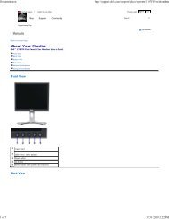
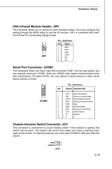
IrDA Infrared Module Header: JIR1<br />
The connector allows you to connect to IrDA Infrared module. You must configure the<br />
setting through the BIOS setup to use the IR function. JIR1 is <strong>com</strong>pliant with Intel ®<br />
Front Panel I/O Connectivity Design Guide.<br />
6<br />
2<br />
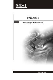
Serial Port Connector: JCOM1<br />
The mainboard offers one 9-pin male DIN connector COM 1 (on the rear panel), and<br />
one optional serial port JCOM1. Both are 16550A high speed <strong>com</strong>munication ports<br />
that send/receive 16 bytes FIFOs. You can attach a serial mouse or other serial<br />
device directly to them.<br />
10 9<br />
2 1<br />
5<br />
1<br />
JIR1<br />
JCOM1<br />
Pin Definition<br />
Pin Signal<br />
1 IRRX<br />
2 IRTX<br />
3 GND<br />
4 VCC5<br />
5 NC<br />
6 NC<br />
PIN SIGNAL DESCRIPTION<br />
1 DCD Data Carry Detect<br />
2 SIN Serial in or receive data<br />
3 SOUT Receive Data Transmit<br />
4 DTR Serial out or transmit data<br />
5 GND Data<br />
6 DSR Data Set Ready<br />
7 RTS Request To Send Ring<br />
8 CTS Clear To Send<br />
9 RI Indicate<br />
10 X X<br />
Pin Definition<br />
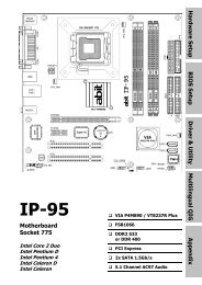
Chassis Intrusion Switch Connector: JCI1<br />
This connector is connected to a 2-pin chassis switch. If the chassis is opened, the<br />
switch will be short. The system will record this status and show a warning message<br />
on the screen. To clear the warning, you must enter the BIOS utility and clear the<br />
record.<br />
GND<br />
CINTRU<br />
JCI1<br />
2<br />
1<br />
2-19