Engine - Disassemble and Assemble (engine ... - Ford Escort Fans
Engine - Disassemble and Assemble (engine ... - Ford Escort Fans
Engine - Disassemble and Assemble (engine ... - Ford Escort Fans

Create successful ePaper yourself
Turn your PDF publications into a flip-book with our unique Google optimized e-Paper software.
«<strong>Escort</strong> '91/'96 Table of Contents»<br />
«Group 21: Basic <strong>Engine</strong>»<br />
«Section 21-06: 1,8 Diesel <strong>Engine</strong>»<br />
«REMOVAL AND INSTALLATION»<br />
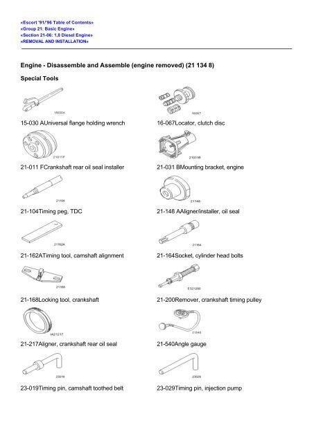
<strong>Engine</strong> - <strong>Disassemble</strong> <strong>and</strong> <strong>Assemble</strong> (<strong>engine</strong> removed) (21 134 8)<br />
Special Tools<br />
15-030 AUniversal flange holding wrench 16-067Locator, clutch disc<br />
21-011 FCrankshaft rear oil seal installer 21-031 BMounting bracket, <strong>engine</strong><br />
21-104Timing peg, TDC 21-148 AAligner/installer, oil seal<br />
21-162ATiming tool, camshaft alignment 21-164Socket, cylinder head bolts<br />
21-168Locking tool, crankshaft 21-200Remover, crankshaft timing pulley<br />
21-217Aligner, crankshaft rear oil seal 21-540Angle gauge<br />
23-019Timing pin, camshaft toothed belt 23-029Timing pin, injection pump
23-03427 mm socket for injectors<br />
Proprietary tools<br />
ÚÄÄÄÄÄÄÄÄÄÄÄÄÄÄÄÄÄÄÄÄÄÄÄÄÄÄÄÄÄÄÄÄÄÄÄÄÄÄÄÄÄÄÄÄÄÄÄÄÄÄÄÄÄÄÄÄÄÄÄÄÄÄÄÄÄÄÄÄÄÄÄÄÄÄÄÄÄÄÄÄÄÄÄÄ¿<br />
³ Description ³<br />
ÃÄÄÄÄÄÄÄÄÄÄÄÄÄÄÄÄÄÄÄÄÄÄÄÄÄÄÄÄÄÄÄÄÄÄÄÄÄÄÄÄÄÄÄÄÄÄÄÄÄÄÄÄÄÄÄÄÄÄÄÄÄÄÄÄÄÄÄÄÄÄÄÄÄÄÄÄÄÄÄÄÄÄÄÄ´<br />
³ Dial gauge ³<br />
ÃÄÄÄÄÄÄÄÄÄÄÄÄÄÄÄÄÄÄÄÄÄÄÄÄÄÄÄÄÄÄÄÄÄÄÄÄÄÄÄÄÄÄÄÄÄÄÄÄÄÄÄÄÄÄÄÄÄÄÄÄÄÄÄÄÄÄÄÄÄÄÄÄÄÄÄÄÄÄÄÄÄÄÄÄ´<br />
³ Measuring fixture ³<br />
ÃÄÄÄÄÄÄÄÄÄÄÄÄÄÄÄÄÄÄÄÄÄÄÄÄÄÄÄÄÄÄÄÄÄÄÄÄÄÄÄÄÄÄÄÄÄÄÄÄÄÄÄÄÄÄÄÄÄÄÄÄÄÄÄÄÄÄÄÄÄÄÄÄÄÄÄÄÄÄÄÄÄÄÄÄ´<br />
³ Piston ring compressor ³<br />
ÃÄÄÄÄÄÄÄÄÄÄÄÄÄÄÄÄÄÄÄÄÄÄÄÄÄÄÄÄÄÄÄÄÄÄÄÄÄÄÄÄÄÄÄÄÄÄÄÄÄÄÄÄÄÄÄÄÄÄÄÄÄÄÄÄÄÄÄÄÄÄÄÄÄÄÄÄÄÄÄÄÄÄÄÄ´<br />
³ Oil filter strap wrench ³<br />
ÃÄÄÄÄÄÄÄÄÄÄÄÄÄÄÄÄÄÄÄÄÄÄÄÄÄÄÄÄÄÄÄÄÄÄÄÄÄÄÄÄÄÄÄÄÄÄÄÄÄÄÄÄÄÄÄÄÄÄÄÄÄÄÄÄÄÄÄÄÄÄÄÄÄÄÄÄÄÄÄÄÄÄÄÄ´<br />
³ New 6 mm drill bit ³<br />
ÃÄÄÄÄÄÄÄÄÄÄÄÄÄÄÄÄÄÄÄÄÄÄÄÄÄÄÄÄÄÄÄÄÄÄÄÄÄÄÄÄÄÄÄÄÄÄÄÄÄÄÄÄÄÄÄÄÄÄÄÄÄÄÄÄÄÄÄÄÄÄÄÄÄÄÄÄÄÄÄÄÄÄÄÄ´<br />
³ Two-legged puller ³<br />
ÃÄÄÄÄÄÄÄÄÄÄÄÄÄÄÄÄÄÄÄÄÄÄÄÄÄÄÄÄÄÄÄÄÄÄÄÄÄÄÄÄÄÄÄÄÄÄÄÄÄÄÄÄÄÄÄÄÄÄÄÄÄÄÄÄÄÄÄÄÄÄÄÄÄÄÄÄÄÄÄÄÄÄÄÄ´<br />
³ Micrometer (25 - 50 mm) ³<br />
ÃÄÄÄÄÄÄÄÄÄÄÄÄÄÄÄÄÄÄÄÄÄÄÄÄÄÄÄÄÄÄÄÄÄÄÄÄÄÄÄÄÄÄÄÄÄÄÄÄÄÄÄÄÄÄÄÄÄÄÄÄÄÄÄÄÄÄÄÄÄÄÄÄÄÄÄÄÄÄÄÄÄÄÄÄ´<br />
³ Micrometer (50 - 75 mm) ³<br />
ÃÄÄÄÄÄÄÄÄÄÄÄÄÄÄÄÄÄÄÄÄÄÄÄÄÄÄÄÄÄÄÄÄÄÄÄÄÄÄÄÄÄÄÄÄÄÄÄÄÄÄÄÄÄÄÄÄÄÄÄÄÄÄÄÄÄÄÄÄÄÄÄÄÄÄÄÄÄÄÄÄÄÄÄÄ´<br />
³ Steel straight edge ³<br />
ÃÄÄÄÄÄÄÄÄÄÄÄÄÄÄÄÄÄÄÄÄÄÄÄÄÄÄÄÄÄÄÄÄÄÄÄÄÄÄÄÄÄÄÄÄÄÄÄÄÄÄÄÄÄÄÄÄÄÄÄÄÄÄÄÄÄÄÄÄÄÄÄÄÄÄÄÄÄÄÄÄÄÄÄÄ´<br />
³ Feeler gauges ³<br />
ÃÄÄÄÄÄÄÄÄÄÄÄÄÄÄÄÄÄÄÄÄÄÄÄÄÄÄÄÄÄÄÄÄÄÄÄÄÄÄÄÄÄÄÄÄÄÄÄÄÄÄÄÄÄÄÄÄÄÄÄÄÄÄÄÄÄÄÄÄÄÄÄÄÄÄÄÄÄÄÄÄÄÄÄÄ´<br />
³ Internal gauge ³<br />
ÃÄÄÄÄÄÄÄÄÄÄÄÄÄÄÄÄÄÄÄÄÄÄÄÄÄÄÄÄÄÄÄÄÄÄÄÄÄÄÄÄÄÄÄÄÄÄÄÄÄÄÄÄÄÄÄÄÄÄÄÄÄÄÄÄÄÄÄÄÄÄÄÄÄÄÄÄÄÄÄÄÄÄÄÄ´<br />
³ Light-metal drift ³<br />
ÃÄÄÄÄÄÄÄÄÄÄÄÄÄÄÄÄÄÄÄÄÄÄÄÄÄÄÄÄÄÄÄÄÄÄÄÄÄÄÄÄÄÄÄÄÄÄÄÄÄÄÄÄÄÄÄÄÄÄÄÄÄÄÄÄÄÄÄÄÄÄÄÄÄÄÄÄÄÄÄÄÄÄÄÄ´<br />
³ Plastic scraper ³<br />
ÀÄÄÄÄÄÄÄÄÄÄÄÄÄÄÄÄÄÄÄÄÄÄÄÄÄÄÄÄÄÄÄÄÄÄÄÄÄÄÄÄÄÄÄÄÄÄÄÄÄÄÄÄÄÄÄÄÄÄÄÄÄÄÄÄÄÄÄÄÄÄÄÄÄÄÄÄÄÄÄÄÄÄÄÄÙ<br />
Workshop Equipment<br />
ÚÄÄÄÄÄÄÄÄÄÄÄÄÄÄÄÄÄÄÄÄÄÄÄÄÄÄÄÄÄÄÄÄÄÄÄÄÄÄÄÄÄÂÄÄÄÄÄÄÄÄÄÄÄÄÄÄÄÄÄÄÄÄÄÄÄÄÄÄÄÄÄÄÄÄÄÄÄÄÄÄÄÄÄ¿<br />
³ Description ³ ³<br />
ÃÄÄÄÄÄÄÄÄÄÄÄÄÄÄÄÄÄÄÄÄÄÄÄÄÄÄÄÄÄÄÄÄÄÄÄÄÄÄÄÄÄÅÄÄÄÄÄÄÄÄÄÄÄÄÄÄÄÄÄÄÄÄÄÄÄÄÄÄÄÄÄÄÄÄÄÄÄÄÄÄÄÄÄ´<br />
³ Mounting st<strong>and</strong> with geared drive ³ 21-187 ³<br />
ÀÄÄÄÄÄÄÄÄÄÄÄÄÄÄÄÄÄÄÄÄÄÄÄÄÄÄÄÄÄÄÄÄÄÄÄÄÄÄÄÄÄÁÄÄÄÄÄÄÄÄÄÄÄÄÄÄÄÄÄÄÄÄÄÄÄÄÄÄÄÄÄÄÄÄÄÄÄÄÄÄÄÄÄÙ<br />
Materials<br />
ÚÄÄÄÄÄÄÄÄÄÄÄÄÄÄÄÄÄÄÄÄÄÄÄÄÄÄÄÄÄÄÄÄÄÄÄÄÄÄÄÄÄÂÄÄÄÄÄÄÄÄÄÄÄÄÄÄÄÄÄÄÄÄÄÄÄÄÄÄÄÄÄÄÄÄÄÄÄÄÄÄÄÄÄ¿<br />
³ Description ³ ³<br />
ÃÄÄÄÄÄÄÄÄÄÄÄÄÄÄÄÄÄÄÄÄÄÄÄÄÄÄÄÄÄÄÄÄÄÄÄÄÄÄÄÄÄÅÄÄÄÄÄÄÄÄÄÄÄÄÄÄÄÄÄÄÄÄÄÄÄÄÄÄÄÄÄÄÄÄÄÄÄÄÄÄÄÄÄ´<br />
³ Plastigage ³ Obtainable through: Replacement ³<br />
³ ³ Services Limited, 30 Euston Street, ³<br />
³ ³ Freemans Industrial Estate, Leicester, ³<br />
³ ³ LE2 7ST ³<br />
ÃÄÄÄÄÄÄÄÄÄÄÄÄÄÄÄÄÄÄÄÄÄÄÄÄÄÄÄÄÄÄÄÄÄÄÄÄÄÄÄÄÄÅÄÄÄÄÄÄÄÄÄÄÄÄÄÄÄÄÄÄÄÄÄÄÄÄÄÄÄÄÄÄÄÄÄÄÄÄÄÄÄÄÄ´<br />
³ Sealant, cylinder block mating face ³ SPM-4G-9112-H ³<br />
³ intersections ³ ³<br />
ÃÄÄÄÄÄÄÄÄÄÄÄÄÄÄÄÄÄÄÄÄÄÄÄÄÄÄÄÄÄÄÄÄÄÄÄÄÄÄÄÄÄÅÄÄÄÄÄÄÄÄÄÄÄÄÄÄÄÄÄÄÄÄÄÄÄÄÄÄÄÄÄÄÄÄÄÄÄÄÄÄÄÄÄ´<br />
³ <strong>Engine</strong> oil SAE 5W-30 ³ WSS-M2C912-A1 ³<br />
ÀÄÄÄÄÄÄÄÄÄÄÄÄÄÄÄÄÄÄÄÄÄÄÄÄÄÄÄÄÄÄÄÄÄÄÄÄÄÄÄÄÄÁÄÄÄÄÄÄÄÄÄÄÄÄÄÄÄÄÄÄÄÄÄÄÄÄÄÄÄÄÄÄÄÄÄÄÄÄÄÄÄÄÄÙ<br />
Dismantle
1. General note.<br />
CAUTION:<br />
In MJ '96 the camshaft timing belt was revised. Coolant pumps <strong>and</strong> timing belt tensioners<br />
with different idler pulleys are fitted in production. In service there are now only coolant<br />
pumps with two edges on the idler pulley available. It should be noted that when renewing<br />
the timing belt tensioner, a tensioner without an edge must not be fitted in conjunction with a<br />
coolant pump without edges. Converting a mechanical timing belt tensioner to an automatic<br />
timing belt tensioner is NOT permissible. In addition, since MY '96 PTFE oil seals have been<br />
fitted at the front <strong>and</strong> rear of the crankshaft instead of the familiar Viton oil seals.<br />
CAUTION:<br />
Since 08.98 (build code WP), a revised oil pump has been fitted in conjunction with a<br />
revised oil pressure switch (green cover), <strong>and</strong> 5W 30 <strong>engine</strong> oil has been used. It should be<br />
noted that up to <strong>and</strong> including 07.98 (build code WM), an oil pressure switch with a black<br />
cover was fitted, <strong>and</strong> 10W-40 <strong>engine</strong> oil was used.<br />
Note:<br />
Installation position of the timing belt tensioner spring <strong>and</strong> the fuel-injection pump spring. DO NOT<br />
mix up the springs.<br />
µ 2. Detach the exhaust gas recirculation valve (EGR valve).<br />
1 Disconnect the hose.<br />
2 Unscrew the bolts.<br />
µ 3. Detach the exhaust manifold.
µ 4. Mount the <strong>engine</strong> on an assembly st<strong>and</strong>.<br />
Fit the mounting bracket.<br />
Mount the <strong>engine</strong> on the assembly st<strong>and</strong>.<br />
5. Drain the <strong>engine</strong> oil.<br />
µ 6. Detach the <strong>engine</strong> mounting.<br />
Note:<br />
Watch out for escaping oil.<br />
7. Detach the oil pump with the oil filter.<br />
µ 8. Detach the alternator.<br />
1 Undo the bolts.<br />
2 Slacken the timing belt <strong>and</strong> remove it.<br />
Detach the alternator.
µ 9. Detach the injection pump belt pulley.<br />
µ 10. Detach the upper <strong>and</strong> lower timing belt covers.<br />
µ 11. Detach the crankcase ventilation hose.<br />
1 To the cylinder block.<br />
2 To the turbocharger.
µ 12. Detach the cylinder head cover.<br />
Remove the gasket.<br />
<strong>Engine</strong>s fitted with an automatic camshaft timing belt tensioner.<br />
µ 13. Undo the bolt of the adjusting cam.<br />
Turn the adjusting cam to 6 o'clock.<br />
<strong>Engine</strong>s fitted with an automatic camshaft timing belt tensioner.<br />
µ 14. Undo the camshaft timing pulley.<br />
Note:<br />
Stop the camshaft timing pulley from turning using the special tool.<br />
Undo the camshaft timing pulley bolt three turns.
<strong>Engine</strong>s fitted with an automatic camshaft timing belt tensioner.<br />
Note:<br />
The timing belt must not be reused.<br />
µ 15. Remove the camshaft timing pulley.<br />
Detach the camshaft timing pulley <strong>and</strong> take it off with the camshaft timing belt.<br />
Discard the timing belt.<br />
<strong>Engine</strong>s fitted with a mechanical camshaft timing belt tensioner.<br />
µ 16. Detach the camshaft timing belt.<br />
Undo the timing belt tensioner clamp bolt <strong>and</strong> slacken the timing belt.<br />
Remove the timing belt.<br />
Tighten the timing belt tensioner clamp bolt.<br />
Discard the timing belt.
<strong>Engine</strong>s fitted with a mechanical camshaft timing belt tensioner.<br />
CAUTION:<br />
The timing belt tensioner is spring-loaded.<br />
µ 17. Detach the timing belt tensioner <strong>and</strong> thecamshaft timing pulley.<br />
1 Timing belt tensioner bolt<br />
Note:<br />
Remove the timing pulley using a two-legged puller.<br />
2 Timing pulley bolt.<br />
µ 18. Detach the injection pump timing belt.<br />
Undo the timing belt tensioner clamp bolt <strong>and</strong> slacken the timing belt.<br />
Tighten the timing belt tensioner clamp bolt.<br />
Remove the timing belt.<br />
CAUTION:<br />
The timing belt tensioner is spring-loaded.<br />
µ 19. Detach the timing belt tensioner <strong>and</strong> the injection pump timing pulley.<br />
1 Timing belt tensioner<br />
2 Timing belt pulley
CAUTION:<br />
The timing belt tensioner is spring-loaded.<br />
µ 20. Detach the timing belt tensioner <strong>and</strong> the camshaft timing pulley.<br />
1 Detach the camshaft timing belt tensioner.<br />
Note:<br />
Remove the camshaft timing pulley using a two-legged puller.<br />
2 Detach the camshaft timing pulley.<br />
Note:<br />
Lock the flywheel using the Special Tool.<br />
µ 21. Detach the crankshaft vibration damper.<br />
µ 22. Remove the rear timing belt covers.
1 Detach the timing pulley.<br />
2 Remove the rear cover bolt.<br />
Remove the covers.<br />
µ 23. Remove the oil dipstick tube together with the mounting.<br />
24. Detach the crankcase ventilation hose.<br />
µ 25. Detach the fuel delivery pipe.<br />
1 Disconnect the hose.<br />
2 Undo the quick-release coupling by pressing it together.<br />
3 Unclip the pipe.<br />
µ 26. Detach the injection pipes <strong>and</strong> leak-off hoses.
µ 27. Remove the fuel-injection pump bracket.<br />
1 Slacken the two bolts.<br />
2 Unscrew the two bolts.<br />
µ 28. Detach the injection pump.<br />
µ 29. Detach the thermostat housing <strong>and</strong> the coolant hose.<br />
30. Detach the alternator bracket.
µ 31. Detach the vacuum pump.<br />
Detach the vacuum pump oil return hose.<br />
µ 32. Detach the fuel filter.<br />
1 Detach the diesel fuel heater from the bracket.<br />
2 Detach the diesel fuel heater <strong>and</strong> the bracket.<br />
µ 33. Remove the auxiliary shaft timing pulley <strong>and</strong> oil seal carrier.<br />
1 Remove the auxiliary shaft timing pulley.<br />
2 Remove the auxiliary shaft oil seal carrier.
µ 34. Remove the auxiliary shaft.<br />
Unscrew the thrust plate bolts.<br />
Withdraw the auxiliary shaft with the thrust plate.<br />
Note:<br />
One bolt holds the bracket for the timing belt tensioner spring.<br />
µ 35. Detach the coolant pump.<br />
CAUTION:<br />
Insert the exp<strong>and</strong>ing part of the puller only, without the centre spindle.<br />
µ 36. Remove the timing pulley from the crankshaft.<br />
1 Insert the exp<strong>and</strong>ing puller.<br />
2 Pull back the exp<strong>and</strong>ing puller until it reaches the stop.
µ 37. Remove the timing pulley from the crankshaft (cont.).<br />
Insert the puller spindle <strong>and</strong> pull the timing pulley off the crankshaft.<br />
µ 38. Remove the injectors <strong>and</strong> glow plugs.<br />
1 Remove the injectors.<br />
Remove the heat shields.<br />
2 Remove the glow plug power supply.<br />
3 Remove the glow plugs.<br />
µ 39. Detach the oil baffle.
µ 40. Detach the cylinder head.<br />
Undo <strong>and</strong> remove the cylinder head bolts in the specified order.<br />
Remove the cylinder head <strong>and</strong> put it down on a soft surface.<br />
Remove the gasket.<br />
µ 41. Remove the crankshaft position sensor with its bracket.<br />
Note:<br />
Lock the flywheel using the Special Tool.<br />
µ 42. Remove the clutch.
µ 43. Remove the flywheel.<br />
Viton oil seals only<br />
µ 44. Remove the crankshaft rear radial oil seal carrier.<br />
PTFE oil seals only<br />
Drive out the oil seal on a flat surface.<br />
Note:<br />
The oil seal carrier is renewed as a unit with the oil seal.<br />
µ 45. Remove the crankshaft rear radial oil seal carrier.
Note:<br />
Remove the sump downwards so that no oil sludge or debris can enter the <strong>engine</strong>.<br />
µ 46. Detach the sump (14 bolts).<br />
µ 47. Detach the front plate.<br />
Prise out the radial oil seal.<br />
µ 48. Remove the oil intake pipe with its bracket.<br />
Remove the O-ring.
CAUTION:<br />
Do not damage the cylinder bore.<br />
µ 49. Remove the pistons with the connecting rods.<br />
Detach the big-end bearing caps.<br />
Remove the crown of carbon around the top of the cylinders using a plastic scraper.<br />
Note:<br />
Keep the big-end shells <strong>and</strong> caps in removal order, ready for re-fitting.<br />
Push the pistons <strong>and</strong> bearing shells out <strong>and</strong> keep them in order.<br />
Note:<br />
Keep the bearing shells <strong>and</strong> caps in removal order, ready for re-fitting.<br />
µ 50. Remove the crankshaft.<br />
Reassemble<br />
Detach the main bearing caps.<br />
Remove the crankshaft.<br />
Remove the bearing shells <strong>and</strong> thrust half washers <strong>and</strong> set them aside in order for re-use.<br />
CAUTION:<br />
A revised timing belt drive has been fitted in production since '96 MY. The timing pulleys,<br />
the timing belt tensioner <strong>and</strong> the timing belt cannot be replaced by components from<br />
previous years.<br />
51. Thoroughly clean all mating faces <strong>and</strong> re-useable parts <strong>and</strong> check them for damage.
µ 52. Clean the piston cooling oil splash nozzles <strong>and</strong> oilways.<br />
Note:<br />
The main bearing caps must be fitted without the main bearing shells, <strong>and</strong> tightened to the<br />
specified torque.<br />
µ 53. Measure the cylinder bores using an internal gauge.<br />
If the measured cylinder bore diameter is too large for the piston classification then the cylinder<br />
block must be overhauled or renewed.<br />
Note:<br />
Repeat the measuring operation at intervals of 90º.<br />
µ 54. Measure the diameters of the main <strong>and</strong> big-end bearing journals.<br />
Different sizes of crankshaft are used in production. The different crankshafts are not<br />
marked.
If the measurements do not agree with those given in the General Specifications, then the<br />
crankshaft must be overhauled or renewed.<br />
55. Preparations for measuring the bearing clearance.<br />
Note:<br />
Carry out the following steps exactly as described.<br />
Measure each bearing surface individually with Plastigage.<br />
Only the bearing cap of the bearing being measured is fitted <strong>and</strong> torqued down to<br />
specification.<br />
The bearing shells <strong>and</strong> the journals must be free of oil.<br />
The measurement should be carried out near the respective dead centre position.<br />
µ 56. Measure the crankshaft main bearing clearances.<br />
Place the matching bearing shells in the cylinder block, free of oil.<br />
Place the crankshaft in the cylinder block, free of oil.<br />
Lay a length of Plastigage thread across the bearing on the bearing journal.<br />
Note:<br />
The bearing cap numbering starts at the timing belt end to which the arrows also point.<br />
µ 57. Measure the main bearing clearances (continued).<br />
Locate each bearing cap in place with its associated bearing shell <strong>and</strong> tighten it up.<br />
Detach the bearing cap.
µ 58. Measure the main bearing clearances (continued).<br />
The measured value shows the bearing clearance.<br />
Renew the bearing shells as necessary.<br />
Note:<br />
Coat the main bearing journals, the bearing shells <strong>and</strong> the thrust half washers with <strong>engine</strong> oil.<br />
µ 59. Install the crankshaft.<br />
Place the thrust half washers in the second main bearing, with the lubrication groove facing<br />
outwards.<br />
Note:<br />
The bearing cap numbering starts at the timing belt end to which the arrows also point. Do not<br />
strike the bearing caps.<br />
Fit the crankshaft main bearing caps with the associated bearing shells.<br />
Tighten the bolts.
Note:<br />
Correct any end float as necessary with the thrust washers at the second main bearing.<br />
µ 60. Check the crankshaft end float.<br />
Set up the dial gauge.<br />
Measure the end float by lifting the crankshaft with a screwdriver.<br />
µ 61. Piston classification.<br />
1 Cylinder bore classification.<br />
2 Piston diameter classification.<br />
3 The weight classes are marked with '+' <strong>and</strong> '-'.<br />
Note:<br />
Piston classification, in case a piston must be replaced.<br />
µ 62. Measure the piston diameters.
CAUTION:<br />
Do not mix up the piston rings. Replace the rings in the same grooves <strong>and</strong> at the same<br />
position.<br />
µ 63. Measure the piston ring gaps.<br />
The values given in General Specifications were obtained with a gauge ring used in production.<br />
When measured in the cylinder, the values may be exceeded by 0,15 mm.<br />
Note:<br />
The piston ring axial clearance must be measured with the ring projecting from its groove.<br />
µ 64. Measure the piston ring clearance.<br />
The maximum piston ring clearance in the piston groove for the upper compression ring is<br />
0,2 mm.<br />
The maximum clearance in the groove for the second compression ring is 0,1 mm.
Note:<br />
Lubricate the pistons <strong>and</strong> cylinder bores with <strong>engine</strong> oil.<br />
µ 65. Install the pistons <strong>and</strong> connecting rods.<br />
Distribute the piston ring gaps evenly around the circumference. This also applies to the<br />
elements of the oil control ring.<br />
Note:<br />
The numbering of the connecting rods starts at the timing belt end. The arrow on the piston<br />
crown points to the timing belt end.<br />
Compress the piston rings using a piston ring compressor.<br />
CAUTION:<br />
Do not damage the cylinder bores <strong>and</strong> bearing surfaces.<br />
Note:<br />
The big-end journal must be at BDC position.<br />
Press the pistons on cylinders 1 <strong>and</strong> 4 into the cylinder with the h<strong>and</strong>le of a hammer while<br />
guiding the connecting rods onto the big-end bearing journals.<br />
Place the clean <strong>and</strong> oil-free bearing shells in their matching big-ends.<br />
Fit the pistons on cylinders 2 <strong>and</strong> 3 in the way described above.<br />
µ 66. Measure the big-end bearing clearances <strong>and</strong> fit the bearing caps.<br />
Measure the big end bearing clearances as described in steps to above.<br />
67. Coat the bearing shells <strong>and</strong> journals with <strong>engine</strong> oil.<br />
Note:<br />
The numbering of the connecting rods <strong>and</strong> big-end bearing caps must be the same.<br />
Fit the appropriate big-end bearing caps <strong>and</strong> bearing shells <strong>and</strong> tighten the bolts.
Note:<br />
Make sure the O-ring is seated correctly.<br />
µ 68. Fit the oil intake pipe with its bracket.<br />
1 Fit the oil intake pipe using a new O-ring.<br />
2 Fit the bracket.<br />
Note:<br />
The mating face of the front plate must be flush with the lower edge of the cylinder block<br />
(tolerance ± 0,1mm).<br />
µ 69. Fit the front plate.<br />
Fit the front plate with a new gasket <strong>and</strong> new rubber oil seals for the oil channels.<br />
1 Centre the front plate using the special tool.<br />
2 Tighten the front plate (4 bolts).
CAUTION:<br />
If a PTFE oil seal (teflon ring) is used, step should be carried out immediately to stop the<br />
oil seal from contracting. Do not remove the support ring from the oil seal until it is about to<br />
be fitted.<br />
µ 70. Install the crankshaft front oil seal.<br />
Fit the oil seal using the special tool <strong>and</strong> the bolt of the vibration damper.<br />
CAUTION:<br />
A revised timing belt drive has been fitted in production since'96 MY. The timing pulleys,<br />
the timing belt tensioner <strong>and</strong> the timing belt cannot be replaced by components from<br />
previous years.<br />
µ 71. Fit the crankshaft timing pulley.<br />
Note:<br />
Condition of O-ring in timing pulley.<br />
Lubricate the O-ring <strong>and</strong> the end of the crankshaft with <strong>engine</strong> oil.<br />
Carefully slide on the pulley as far as it will go.<br />
The locating pin on the end of the crankshaft <strong>and</strong> the hole in the timing pulley must line up.<br />
Note:<br />
The sump bolts must be tightened within 20 minutes of applying the sealer.<br />
µ 72. Apply sealer (SPM-4G-9112-H) to the joints on the cylinder block mating face.
µ 73. Fit the sump.<br />
Locate the sump in place with a new gasket <strong>and</strong> screw in the bolts (x14) finger tight.<br />
Make sure that the sump is flush with the cylinder block.<br />
µ 74. Tighten the sump bolts.<br />
PTFE oil seals only<br />
CAUTION:<br />
The seal lip of the oil seal <strong>and</strong> the sealing surface on the crankshaft must be free of oil.<br />
CAUTION:<br />
The support ring is automatically pushed out of the oil seal when the oil seal carrier is<br />
fitted in place. Do not remove it beforeh<strong>and</strong>.
µ 75. Fit a new crankshaft rear oil seal carrier.<br />
Locate a new oil seal carrier with integrated oil seal together with the bolts in installation<br />
position.<br />
Insert the bolts.<br />
Insert the special tool <strong>and</strong> centrally align the oil seal carrier on the crankshaft.<br />
PTFE oil seals only<br />
CAUTION:<br />
If the special tool cannot be removed, then the sump must be re-aligned.<br />
µ 76. Tighten the bolts on the crankshaft oil seal carrier.<br />
Remove the special tool.<br />
CAUTION:<br />
Renew the bolts.<br />
µ 77. Fit the flywheel (8 bolts).<br />
Lock the crankshaft using Special Tool 21-168.
µ 78. Fit the CKP sensor together with its bracket.<br />
µ 79. Fit the coolant pump.<br />
Locate the coolant pump in installation position, together with a new gasket <strong>and</strong> the bracket for<br />
the timing belt tensioner spring.<br />
Note:<br />
The lubricating grooves on the thrust plate must face outwards.<br />
µ 80. Fit the auxiliary shaft.<br />
Lubricate the auxiliary shaft, the bearing bush in the cylinder block <strong>and</strong> the thrust plate with<br />
<strong>engine</strong> oil.<br />
Fit the auxiliary shaft with the thrust plate.
CAUTION:<br />
If the plastic fitting bush is removed from the oil seal carrier before assembly then the oil<br />
seal is rendered useless.<br />
µ 81. Fit the auxiliary shaft oil seal carrier.<br />
Lubricate the end of the auxiliary shaft with <strong>engine</strong> oil.<br />
Push a new oil seal carrier with an integrated oil seal <strong>and</strong> plastic fitting bush onto the end of<br />
the auxiliary shaft.<br />
Tighten the bolts on the oil seal carrier.<br />
After securing the oil seal housing, detach the plastic fitting bush <strong>and</strong> check that the seal is<br />
seated correctly.<br />
Note:<br />
Make two measurements per cylinder, five millimetres in from the piston edge.<br />
µ 82. Measure the piston protrusion.<br />
Measure the piston protrusion of each cylinder when it is at TDC<br />
Measure the difference in height between the piston crown <strong>and</strong> the cylinder block.<br />
The largest measurement decides the thickness of the cylinder head gasket (see General<br />
Specifications).
µ 83. Line up the crankshaft <strong>and</strong> camshaft.<br />
Turn the crankshaft until the piston of cylinder no. 1 is at TDC.<br />
Turn the camshaft until the slot in the eccentric on the camshaft is parallel with the upper<br />
edge of the cylinder head (with the larger semi-circle at the top).<br />
The crankshaft <strong>and</strong> camshaft must not be turned any further.<br />
Note:<br />
The cylinder head gasket is marked ”TOP/OBEN".<br />
µ 84. Fit the new cylinder head gasket.<br />
1 Check that the locating sleeves are seated correctly.<br />
2 Thickness identification notches.<br />
Note:<br />
Renew the cylinder head bolts.
µ 85. Tighten the cylinder head bolts.<br />
Screw in the cylinder head bolts.<br />
Tighten the cylinder head bolts in two stages in the specified sequence.<br />
Note:<br />
The cylinder head bolts must not be re-tightened.<br />
µ 86. Tighten the cylinder head bolts (cont.).<br />
CAUTION:<br />
For the third stage, first undo one bolt by the angle shown, then tighten it to the<br />
specified torque <strong>and</strong> then apply the angular torque. Only then move on to the next bolt.<br />
Wait three minutes <strong>and</strong> then tighten the cylinder head bolts to stage 3 in the specified sequence.<br />
Note:<br />
The heat shield is correctly installed with the conical side downwards. Use new heat shields.<br />
µ 87. Install the injectors <strong>and</strong> glow plugs.<br />
1 Install the injectors with the heat shields.<br />
2 Install the glow plugs.<br />
3 Install the glow plug power supply.
µ 88. Fit the fuel filter.<br />
1 Fit the bracket with the fuel filter.<br />
2 Attach the diesel fuel heater to the bracket.<br />
µ 89. Fit the vacuum pump.<br />
Connect the oil return hose.<br />
Place the vacuum pump <strong>and</strong> new O-ring, glow plug bracket <strong>and</strong> vacuum pump bolts in<br />
position.<br />
Tighten the bolts.<br />
µ 90. Fit the thermostat housing <strong>and</strong> the coolant hose.<br />
91. Fit the alternator bracket.
µ 92. Fit the fuel-injection pump.<br />
µ 93. Fit the fuel-injection pump bracket.<br />
µ 94. Connect the injection pipes <strong>and</strong> the leak-off hoses.
µ 95. Install the fuel feed pipe.<br />
1 Fuel pipe quick-release coupling<br />
2 Clip the pipe in place.<br />
3 Connect the hose.<br />
µ 96. Fit the dipstick tube together with its bracket.<br />
97. Install the crankcase ventilation hose.<br />
µ 98. Fit the rear timing belt covers.<br />
Locate the covers in installation position.<br />
1 Install the timing pulley.<br />
2 Screw in the bolt.
Note:<br />
The auxiliary shaft locating pin <strong>and</strong> the hole in the timing pulley must line up.<br />
µ 99. Fit the pulleys <strong>and</strong> the camshaft timing belt tensioner.<br />
1 Fit the camshaft timing pulley.<br />
2 Fit the auxiliary shaft pulley (one bolt).<br />
3 Secure the timing belt tensioner (2 bolts).<br />
4 Compress timing belt tensioner spring <strong>and</strong> lock it using a bolt.<br />
Note:<br />
Do not tighten the bolts.<br />
µ 100. Fit the injection pump timing pulley.<br />
Set the pulley so that the bolts are central in the slots.<br />
µ 101. Fit the injection pump timing belt tensioner.
Compress timing belt tensioner spring <strong>and</strong> lock it using a bolt.<br />
Note:<br />
Use a new bolt.<br />
µ 102. Fit the crankshaft vibration damper.<br />
Lock the crankshaft.<br />
Note:<br />
The lug <strong>and</strong> the notch must line up.<br />
Coat the underside of the bolt head on the vibration damper with <strong>engine</strong> oil <strong>and</strong> tighten it to<br />
the specified torque.<br />
<strong>Engine</strong>s fitted with an automatic camshaft timing belt tensioner.<br />
µ 103. Fit the special tool in the camshaft groove.<br />
104. Set the crankshaft to TDC.<br />
Remove the retaining bolt from the cylinder block.<br />
Note:<br />
Screw in the special tool as far as it will go.<br />
Fit Special Tool 21-104 <strong>and</strong> carefully turn the crankshaft in the direction of rotation of the<br />
<strong>engine</strong> until it comes up against the special tool.
<strong>Engine</strong>s fitted with an automatic camshaft timing belt tensioner.<br />
CAUTION:<br />
Always renew the camshaft timing belt <strong>and</strong> the fuel pump timing belt.<br />
CAUTION:<br />
Only carry out work on the timing belt at workshop temperature.<br />
Note:<br />
The crankshaft must be touching Special Tool 21-104 <strong>and</strong> Special Tool 21-162B must be inserted<br />
in the camshaft.<br />
Note:<br />
The direction of rotation is marked.<br />
Note:<br />
Make sure the timing belt is seated correctly.<br />
µ 105. Fit the new camshaft timing belt.<br />
1 Install the camshaft timing belt tensioner.<br />
2 Install the adjusting cam.<br />
3 Locate the timing belt in position.<br />
Slide the camshaft timing pulley onto the taper <strong>and</strong> tighten the bolt until the pulley only just turns<br />
on the camshaft.<br />
<strong>Engine</strong>s fitted with an automatic camshaft timing belt tensioner.<br />
µ 106. Pre-tension the camshaft timing belt.
Note:<br />
Coat the bolt contact surface of the adjusting cam with <strong>engine</strong> oil.<br />
Turn the adjusting cam clockwise to 9 o'clock <strong>and</strong> tighten the adjuster bolt.<br />
<strong>Engine</strong>s fitted with an automatic camshaft timing belt tensioner.<br />
Note:<br />
Stop the camshaft timing pulley from turning using the special tool.<br />
µ 107. Tighten the camshaft timing pulley bolt.<br />
<strong>Engine</strong>s fitted with an automatic camshaft timing belt tensioner.<br />
CAUTION:<br />
Remove Special Tools 21-104 <strong>and</strong> 21-162B.<br />
108. Turn the crankshaft six turns in its running direction.<br />
<strong>Engine</strong>s fitted with an automatic camshaft timing belt tensioner.<br />
µ 109. Preparations for tensioning the timing belt.<br />
Turn the crankshaft in the normal direction of rotation until the slot on the injection pump<br />
timing pulley is at 11 o'clock.<br />
Note:<br />
The special tool must be screwed in as far as it will go.<br />
Screw in the special tool.<br />
Carefully turn the crankshaft in the normal direction of rotation of the <strong>engine</strong> until it comes up<br />
against the special tool.
<strong>Engine</strong>s fitted with an automatic camshaft timing belt tensioner.<br />
µ 110. Undo the bolt on the adjusting cam half a turn.<br />
<strong>Engine</strong>s fitted with an automatic camshaft timing belt tensioner.<br />
Note:<br />
Stop the camshaft timing pulley from turning using the special tool.<br />
µ 111. Undo the camshaft timing pulley bolt three turns.<br />
<strong>Engine</strong>s fitted with an automatic camshaft timing belt tensioner.<br />
Note:<br />
Insert a screwdriver between the camshaft timing pulley <strong>and</strong> the timing belt rear cover.<br />
µ 112. Loosen the camshaft timing pulley from the taper by lightly tapping the light-metal drift.
<strong>Engine</strong>s fitted with an automatic camshaft timing belt tensioner.<br />
Note:<br />
If necessary, rotate the camshaft until the timing tool can be inserted.<br />
µ 113. Insert the special tool.<br />
<strong>Engine</strong>s fitted with an automatic camshaft timing belt tensioner.<br />
Note:<br />
Check that the camshaft timing pulley is still free to turn on the camshaft.<br />
µ 114. Tighten the camshaft timing pulley bolt finger tight <strong>and</strong> loosen one half turn.<br />
<strong>Engine</strong>s fitted with an automatic camshaft timing belt tensioner.<br />
µ 115. Tension the camshaft timing belt.
Note:<br />
The adjustment range of the adjusting cam lies between 6 o'clock (MIN) <strong>and</strong> 12 o'clock (MAX).<br />
Tension the camshaft timing belt by turning the adjusting cam clockwise so that the arrow of the<br />
automatic camshaft timing belt tensioner is located in the right-h<strong>and</strong> corner of the<br />
adjustment range.<br />
<strong>Engine</strong>s fitted with an automatic camshaft timing belt tensioner.<br />
Note:<br />
Hold the adjusting cam in position.<br />
µ 116. Tighten the adjusting cam bolt evenly.<br />
<strong>Engine</strong>s fitted with an automatic camshaft timing belt tensioner.<br />
µ 117. Checking the position of the automatic camshaft timing belt tensioner.<br />
If the pointer is in range A: proceed to the next step.<br />
If the pointer is outside range A, tension the camshaft timing belt again as described.<br />
CAUTION:<br />
To avoid damage to the <strong>engine</strong>, make sure that the pointer is in range "A".
<strong>Engine</strong>s fitted with an automatic camshaft timing belt tensioner.<br />
Note:<br />
Stop the camshaft timing pulley from turning using the special tool.<br />
µ 118. Tighten the bolt of the camshaft timing pulley.<br />
Tightening torque for M8 bolt: 35 Nm<br />
Tightening torque for M10 bolt: 48 Nm<br />
<strong>Engine</strong>s fitted with an automatic camshaft timing belt tensioner.<br />
119. Remove Special Tools 21-104 <strong>and</strong> 21-162B.<br />
<strong>Engine</strong>s fitted with an automatic camshaft timing belt tensioner.<br />
µ 120. Checking the valve timing.<br />
Turn the crankshaft in the normal direction of rotation until the slot on the injection pump<br />
timing pulley is at 11 o'clock.<br />
Note:<br />
The special tool must be screwed in as far as it will go.<br />
Screw in the special tool.<br />
Carefully turn the crankshaft in the normal direction of rotation of the <strong>engine</strong> until it comes up<br />
against the special tool.
<strong>Engine</strong>s fitted with an automatic camshaft timing belt tensioner.<br />
µ 121. Install the special tool. If the special tool cannot be inserted, tension the camshaft timing belt<br />
again as described.<br />
<strong>Engine</strong>s fitted with an automatic camshaft timing belt tensioner.<br />
µ 122. Checking the position of the automatic timing belt tensioner.<br />
If the pointer is in range A: proceed to the next step.<br />
If the pointer is outside range A, tension the camshaft timing belt again as described.<br />
CAUTION:<br />
To avoid damage to the <strong>engine</strong>, ensure that the pointer is located within range ”A".<br />
<strong>Engine</strong>s fitted with an automatic camshaft timing belt tensioner.<br />
123. Remove Special Tools 21-162B <strong>and</strong> 21-104.
<strong>Engine</strong>s fitted with a mechanical camshaft timing belt tensioner.<br />
CAUTION:<br />
Always renew the camshaft timing belt <strong>and</strong> the injection pump timing belt.<br />
Note:<br />
The springs of the timing belt tensioners are not interchangeable.<br />
µ 124. Fit the new camshaft timing belt.<br />
Insert Special Tool 23-019.<br />
Note:<br />
Make sure the timing belt is seated correctly <strong>and</strong> positioned in the correct direction of rotation.<br />
Note:<br />
Slots. The bolts of the camshaft timing belt pulley must be central in the slots.<br />
Fit a new camshaft timing belt anti-clockwise starting from the crankshaft.<br />
Undo the mechanical belt tensioner clamp bolt <strong>and</strong> allow the tensioner to snap against the<br />
belt.<br />
1 Tighten the bolt of the mechanical timing belt tensioner.<br />
2 Tighten the bolts of the camshaft timing belt pulley.<br />
<strong>Engine</strong>s fitted with a mechanical camshaft timing belt tensioner.<br />
µ 125. Preparations for tensioning the timing belt.<br />
CAUTION:<br />
Remove Special Tools 21-104 <strong>and</strong> 23-019.<br />
Carefully turn the crankshaft six revolutions in the normal direction of rotation.<br />
1 Screw in the special tool.<br />
Carefully turn the crankshaft in the normal direction of rotation of the <strong>engine</strong> until it comes up<br />
against the special tool.<br />
2 It must be possible to insert the special tool into the camshaft timing pulley.<br />
3 Undo the bolts of the camshaft timing belt pulley.
<strong>Engine</strong>s fitted with a mechanical camshaft timing belt tensioner.<br />
CAUTION:<br />
A used timing belt cannot be re-tensioned.<br />
µ 126. Tension the timing belt.<br />
Slacken the bolts of the mechanical camshaft timing belt tensioner a quarter of a turn so<br />
that the timing belt tensioner presses against the timing belt.<br />
Note:<br />
Check the special tools are seated correctly.<br />
1 Tighten the bolts of the mechanical camshaft timing belt tensioner.<br />
2 Tighten the bolts of the camshaft timing belt pulley.<br />
3 Remove the special tool.<br />
4 Remove the special tool <strong>and</strong> tighten the retaining bolt to 24 Nm.<br />
µ 127. Align the injection pump timing belt pulley.<br />
1 Using the special tool or a new 6 mm drill bit, align the injection pump timing belt pulley<br />
through the timing pulley recess <strong>and</strong> the hole in the injection pump housing.<br />
Unscrew the blanking plug from the hole for TDC adjustment in the cylinder block.<br />
2 Screw the special tool into the cylinder block.<br />
Note:<br />
The special tool must be screwed in as far as it will go. The crankshaft must be touching the<br />
special tool.<br />
Carefully turn the crankshaft in the normal direction of rotation of the <strong>engine</strong> until it comes up<br />
against the special tool.
CAUTION:<br />
Use a new timing belt.<br />
Note:<br />
The direction of rotation is marked.<br />
Note:<br />
Make sure the timing belt is seated correctly.<br />
µ 128. Fit the injection pump timing belt.<br />
Fit a new timing belt anti-clockwise starting from the crankshaft.<br />
Undo the belt tensioner clamp bolt <strong>and</strong> allow the tensioner to snap against the belt.<br />
1 Tighten the belt tensioner clamp bolt.<br />
Note:<br />
The bolts must not be at the ends of the slots.<br />
2 Tighten the bolts of the fuel-injection pump pulley.<br />
Remove the special tool.<br />
µ 129. Check the valve clearances <strong>and</strong> adjust them if necessary as described in «Operation Number<br />
21 213 0».<br />
130. Fit the oil baffle.
Note:<br />
Clean the gasket, check it for damage <strong>and</strong> coat it with <strong>engine</strong> oil. If necessary, renew it (it can be<br />
used several times).<br />
µ 131. Fit the cylinder head cover.<br />
µ 132. Insert the plastic tray in the alternator bracket.<br />
µ 133. Install the upper <strong>and</strong> lower timing belt covers.
µ 134. Fit the injection pump belt pulley.<br />
µ 135. Fit the alternator.<br />
Insert the bolts.<br />
Lay the drive belt in place.<br />
1 Tension the drive belt.<br />
2 Tighten the bolt.<br />
3 Tighten the remaining bolts.<br />
µ 136. Centre the clutch disc on the clutch pressure plate.
µ 137. Install the clutch.<br />
1 Install the clutch pressure plate/centred clutch disc assembly.<br />
2 Tighten the six bolts uniformly, working diagonally.<br />
3 Remove the special tool.<br />
Note:<br />
Use a new gasket.<br />
Note:<br />
Coat the oil pump drive gear with oil.<br />
µ 138. Fit the oil pump <strong>and</strong> oil filter.<br />
139. Remove <strong>engine</strong> mounting bracket.<br />
µ 140. Remove the <strong>engine</strong> from assembly st<strong>and</strong>.<br />
Note:
Tightening order.<br />
Note:<br />
Plastic sleeve on right-h<strong>and</strong> upper stud (no. 7).<br />
141. Fit the exhaust manifold with a new gasket.<br />
µ 142. Fit the EGR valve with a new seal.<br />
1 Tighten the bolts.<br />
2 Tighten the clamp bolt.<br />
3 Connect the hose.