ROTARY SPOA7-9 SPO9 400 SERIES INSTALL.pdf
ROTARY SPOA7-9 SPO9 400 SERIES INSTALL.pdf
ROTARY SPOA7-9 SPO9 400 SERIES INSTALL.pdf

You also want an ePaper? Increase the reach of your titles
YUMPU automatically turns print PDFs into web optimized ePapers that Google loves.
R<br />
O TARY<br />
L IF<br />
T<br />
V A L I D A T E D<br />
CERTIFIED<br />
B Y E<br />
T L<br />
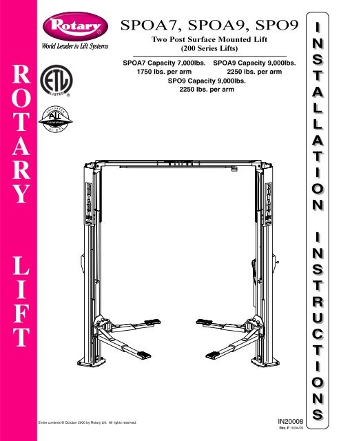
<strong>SPOA7</strong>, SPOA9, <strong>SPO9</strong><br />
Two Post Surface Mounted Lift<br />
(200 Series Lifts)<br />
<strong>SPOA7</strong> Capacity 7,000lbs. SPOA9 Capacity 9,000lbs.<br />
1750 lbs. per arm 2250 lbs. per arm<br />
<strong>SPO9</strong> Capacity 9,000lbs.<br />
2250 lbs. per arm<br />
Entire contents © October 2000 by Rotary Lift. All rights reserved. IN20008<br />
Rev. P 10/04/00<br />
I<br />
N<br />
S<br />
T<br />
A<br />
L<br />
L<br />
A<br />
T<br />
I<br />
O<br />
N<br />
I<br />
N<br />
S<br />
T<br />
R<br />
U<br />
C<br />
T<br />
I<br />
O<br />
N<br />
S
Wheel Spotting Dish<br />
2' 2"<br />
(657mm)<br />
18"<br />
(457mm)<br />
2' 5"<br />
(737mm)<br />
APPROACH<br />
6' 0" (1829mm) minimum to nearest<br />
obstruction or bay. 7' 0" (2134mm)<br />
minimum to nearest wall.<br />
Power Unit<br />
(Passenger Side)<br />
7' 11-3/8" (2423mm) <strong>SPOA7</strong>*<br />
7' 3-3/8" (2219mm) <strong>SPOA7</strong>NB (Narrow Bay)*<br />
8' 5-3/8" (2575mm) SPOA9*<br />
2<br />
9' 0" (2743mm) minimum<br />
to nearest obstruction<br />
15' 0" (4572mm) minimum<br />
to nearest obstruction<br />
*NOTE: Dimension is from Inside of Baseplate to Inside of Baseplate. Fig. 1a<br />
Wheel Spotting Dish<br />
3' 10"<br />
(1178mm)<br />
15"<br />
(381mm)<br />
2' 5"<br />
(737mm)<br />
APPROACH<br />
8' 11-5/8" (2734mm) <strong>SPO9</strong>*<br />
6' 0" (1829mm) minimum to<br />
nearest obstruction or bay.<br />
7' 0" (2134mm) minimum to<br />
nearest wall.<br />
Power Unit<br />
(Passenger Side)<br />
*NOTE: Dimension is from Inside of Baseplate to Inside of Baseplate.<br />
11' 0" (3353mm)<br />
minimum to nearest<br />
obstruction<br />
13' 0" (3963mm)<br />
minimum to nearest<br />
obstruction<br />
Fig. 1b
1. Lift Location: Use architects plan when<br />
available to locate lift. Fig. 1a & Fig. 1b shows<br />
dimensions of a typical bay layout.<br />
2. Lift Height: See Fig. 4 for overall lift height of<br />
each specific lift model. Add 1” min. to overall<br />
height to lowest obstruction.<br />
WARNING DO NOT install this lift in a pit<br />
or depression due to fire or explosion risks.<br />
3. Column Extensions: Before standing columns<br />
upright, install the column extensions using (12)<br />
3/8”-16NC x 1/2” Flanged HHCS, Fig. 4.<br />
4. Latch Cable Guides: Install the latch cable<br />
guides to column extensions with (4) 1/4”-20NC x<br />
1” HHCS and 1/4”-20NC Flanged Locknuts, Fig. 1c,<br />
Fig. 1d, & Fig. 10b.<br />
NOTE: Latch cable guide must be toward approach<br />
side of the column extension. Coat the cable contact<br />
surface with a light grease such as “TUFOIL”.<br />
1/4"-20NC x 1"<br />
HHCS & 1/4"<br />
Flanged Locknut<br />
Latch Cable<br />
Guide<br />
Latch Cable<br />
Guide<br />
1/4"-20NC x 1"<br />
HHCS & 1/4"<br />
Flanged Locknut<br />
<strong>SPOA7</strong>/SPOA9<br />
Column<br />
Extension<br />
APPROACH<br />
<strong>SPO9</strong><br />
Column<br />
Extension<br />
APPROACH<br />
Fig. 1c<br />
Fig. 1d<br />
4-1/4"<br />
Drill holes using<br />
3/4" carbide<br />
tipped masonary<br />
drill bit per ANSI<br />
standard<br />
B94.12.1977<br />
3<br />
Clean hole.<br />
Run nut down just<br />
below impact section<br />
of bolt. Drive anchor<br />
into hole until nut and<br />
washer contact base.<br />
4-1/4"<br />
2-1/4"<br />
3-1/4"<br />
Tighten nut with<br />
Torque wrench to<br />
150 ft.-lbs.<br />
Fig. 2<br />
Installation torque of 150 ft-lbs. is required for all anchor bolts.<br />
Anchor<br />
Shims<br />
(1/2" Max.)<br />
Fig. 3<br />
Nut<br />
Flat<br />
Washer<br />
NOTE: Use<br />
rectangular shims at<br />
inside edge of<br />
baseplate. Use<br />
constructions<br />
adhesive or silicon<br />
cement to hold shim<br />
in place. INSURE<br />
shims are held tightly<br />
between base plate<br />
and floor after<br />
torquing anchors.<br />
NOTE: If more than 2 horse shoe shims are used at any of the column<br />
anchor bolts, pack non-shrink grout under the unsupported area of the<br />
column base. Insure shims are held tightly between the baseplate and<br />
floor after torquing anchors.<br />
Overhead Assembly<br />
12' 0" (3658mm)<br />
Top of Cylinder<br />
11' 8" (3556mm)<br />
Top of Overhead<br />
Assembly(std.)<br />
11' 4" (3454mm)<br />
Top of Overhead<br />
Assembly<br />
(Low Ceiling)<br />
All above for<br />
both <strong>SPOA7</strong><br />
and SPOA9<br />
(Low Ceiling is<br />
N/A for <strong>SPO9</strong>)<br />
3/8"-16NCx1" HHCS<br />
& Flanged Locknut<br />
(2)3/8" Star Lockwashers<br />
on right side only<br />
Use (4) 3/8"-16NCx1/2"<br />
Flanged HHCS in front<br />
and (2) in the back<br />
Use (1) 3/8" Star<br />
Lockwasher on right extension<br />
Fig. 4<br />
IMPORTANT: All star washers are to be mounted on the right<br />
side column to ensure grounding of overhead limit switch. Star<br />
washers are not needed when mounting to left side column.<br />
Notice the column extension mounting, Fig. 4 and overhead limit<br />
switch mounting as well in Fig. 6.
5. Lift Setting: Position columns in bay using<br />
dimensions shown in Fig. 1a & Fig. 1b. Place column<br />
with power unit mounting bracket on vehicle passenger<br />
side of lift. Both column base plate backs must be square<br />
on center line of lift. Notches are cut into each base plate<br />
to indicate center line of lift.<br />
Use appropriate equipment to raise carriage to first latch<br />
position. Be sure locking latch is securely engaged.<br />
B<br />
C<br />
C<br />
Concrete and Anchoring: Concrete shall have a<br />
compression strength of at least 3,000 PSI and a minimum<br />
thickness of 4-1/4" in order to achieve a minimum anchor<br />
embedment of 3-1/4". When using the standard supplied<br />
3/4” x 5-1/2” lg. anchors, if the top of the anchor exceeds<br />
2-1/4” above the floor grade, you DO NOT have enough<br />
embedment.<br />
Drill (10) 3/4" dia. holes in concrete floor using holes in<br />
column base plate as a guide. See Fig. 2 and Fig. 5 for<br />
hole depth, hole spacing, and edge distance requirements.<br />
CAUTION DO NOT install on asphalt or other<br />
similar unstable surfaces. Columns are<br />
supported only by anchors in floor.<br />
6. IMPORTANT: Using the horse shoe shims<br />
provided, shim each column base until each column is<br />
plumb. If one column has to be elevated to match the<br />
plane of the other column, full size base shim plates<br />
should be used (Reference FA5112 Shim Kit). Recheck<br />
columns for plumb. Tighten anchor bolts to an<br />
installation torque of 150 ft-lbs. Shim thickness MUST<br />
NOT exceed 1/2” when using the 5-1/2” long anchors<br />
provided with the lift. Adjust the column extensions<br />
plumb.<br />
B<br />
C<br />
C<br />
A<br />
Fig. 5<br />
A) Concrete Thickness &<br />
Hole Depth 4-1/4" (108mm)<br />
B) Edge Distance 4-3/4" (121mm)<br />
C) Hole Spacing 6-1/2" (165mm)<br />
4<br />
If anchors do not tighten to 150 ft-lbs. installation torque,<br />
replace concrete under each column base with a 4' x 4' x<br />
6" thick 3000 PSI minimum concrete pad keyed under and<br />
flush with the top of existing floor. Let concrete cure<br />
before installing lifts and anchors.<br />
7a. Overhead Assembly: Fig. 6: Adjust overhead to<br />
appropriate dimension. Install (4) 3/8"-16NC x 3/4"<br />
HHCS & 3/8”-16NC Flanged Locknuts, do not tighten.<br />
Mount switch assembly towards power unit column as<br />
shown, using (2) 1/4"-20NC x 3/4" lg. HHCS, 1/4”-20NC<br />
Nuts and 1/4" Star Washers. For Narrow Bay installation,<br />
see step 7b, all others go to step 7c.<br />
7b. For Narrow Bay installation only: Cut off 11” from<br />
the length of the bar and cushion on the end opposite the<br />
1/4” mounting hole. Continue to step 7c.<br />
7c. Continued Overhead Assembly: Insert 1/4"-20NC<br />
x 2" HHCS through pivot hole in end of switch bar. Insert<br />
opposite end of bar through slot in switch mounting<br />
bracket. Then secure HHCS and Switch Bar to overhead<br />
as shown, using 3/4" spacer and 1/4”-20NC Locknut.<br />
Tighten Hex bolt leaving 1/16” gap between the spacer<br />
and the overhead assembly.<br />
8. Overhead Installation: Install overhead assembly to<br />
column extensions with (2) star washers and (8) 3/8" x 1"<br />
HHCS and 3/8” Flanged Locknuts, Fig. 4. Tighten bolts<br />
at center of overhead assembly.<br />
9. Power Unit: First install (1) star washer onto one of<br />
the (4) 5/16"-18NC x 1-1/2" HHCS. This is very<br />
important for grounding. Put the (4) 5/16"-18NC x 1-1/2"<br />
HHCS thru holes in power unit bracket using Push-Nuts<br />
to hold in place, Fig. 7a & Fig. 7b. Mount unit with motor<br />
up to column bracket and install (4) 5/16” star washers<br />
and 5/16” Nuts. Install and hand tighten Branch Tee to<br />
pump until O-ring is seated. Then tighten locknut to 35-40<br />
ft-lbs, and connect supply hoses to Tee, Fig. 8a or Fig. 8b.<br />
NOTE: Over tightening locknut may tear O-ring.
Spacer<br />
Spacer<br />
Spacer<br />
Spacer<br />
3/8"-16NC x 3/4" HHCS<br />
& Flanged Locknut<br />
1/4"-20NC x 2" HHCS<br />
& 1/4" Locknut<br />
3/8"-16NC x 3/4" HHCS<br />
& Flanged Locknut<br />
5<br />
<strong>SPOA7</strong><br />
1/4"-20NC x 2" HHCS<br />
& 1/4" Locknut 1/4"-20NC x 3/4" HHCS, Star Lockwasher, and Nut<br />
105-3/8"<br />
SPOA9<br />
1/4"-20NC x 3/4" HHCS, Star Lockwasher, and Nut<br />
111-3/8"<br />
3/8"-16NC x 3/4" HHCS<br />
& Flanged Locknut<br />
<strong>SPO9</strong><br />
1/4"-20NC x 2" HHCS<br />
& 1/4" Locknut 1/4"-20NC x 3/4" HHCS, Star Lockwasher, and Nut<br />
3/8"-16NC x 3/4" HHCS<br />
& Flanged Locknut<br />
114"<br />
1/4"-20NC x 2" HHCS & 1/4" Locknut<br />
<strong>SPOA7</strong> Narrow Bay<br />
1/4"-20NC x 3/4" HHCS, Star Lockwasher, and Nut<br />
97-3/8"<br />
7-3/4"<br />
11-3/4"<br />
7-3/4"<br />
7-3/4"<br />
Fig. 6
Use (4)5/16"-18NC<br />
x1-1/2" lg. HHCS<br />
and Nuts<br />
On one bolt, place<br />
(2)5/16" Star Washers<br />
Fig. 7a<br />
Raise<br />
Switch<br />
Lowering<br />
Valve<br />
Crimped Hose<br />
Sleeve(typical)<br />
Raise<br />
Switch<br />
Lowering<br />
Valve<br />
Fill-Breather<br />
Cap<br />
Fill-Vent<br />
Screw<br />
PUSH<br />
LEVER<br />
TO<br />
LOWER<br />
PUSH<br />
LEVER<br />
TO<br />
LOWER<br />
NOTICE<br />
ALLOW 2 SECONDS<br />
BETWEEN MOTOR STARTS<br />
FAILURE TO COMPLY MAY<br />
CAUSE MOTOR BURNOUT<br />
PUSH BUTTON TO RAISE<br />
CAPACITY<br />
7000 LBS.<br />
HYDRAULIC AU POWER UNIT<br />
FILL INSTRUCTIONS: CTION Lower lift. Remove fill cap<br />
and socket head ad ven vent plug. Fill to vent hole with clean<br />
Dexron II ATF<br />
For Parts & Servic Service contact: (800) 445-5438<br />
<strong>ROTARY</strong> LIFT FT / / A<br />
DOVER INDUSTRIES CO.<br />
Push nuts hold bolts to brackets.<br />
Branch<br />
Tee<br />
CAPACITY<br />
9,000 LBS.<br />
For SPOA9/<strong>SPO9</strong><br />
Fill Breather Cap<br />
Overhead Hose<br />
Branch Tee<br />
Overhead<br />
Hose<br />
Power Unit<br />
Hose<br />
Use (4) 5/16"-18NC<br />
x 1-1/2" HHCS, and<br />
5/16"-18NC Nuts<br />
On one bolt,<br />
place 5/16"<br />
Star Washers.<br />
Push-nuts<br />
hold bolts<br />
to bracket.<br />
NOTICE<br />
ALLOW 2 SECONDS<br />
BETWEEN MOTOR STARTS<br />
FAILURE TO COMPLY MAY<br />
CAUSE MOTOR BURNOUT<br />
PUSH BUTTON TO RAISE<br />
CAPACITY<br />
7,000 LBS.<br />
NP241<br />
For <strong>SPOA7</strong><br />
Fig. 7b<br />
Fig. 8a<br />
6<br />
<br />
<br />
<br />
<br />
<br />
<br />
FOR 3 PHASE POWER UNITS ONLY:<br />
Attach Control Plate to Motor using (4)<br />
5mm-.80 x 8mm lg. Flat Head Machine Screws<br />
CAPACITY<br />
9,000 LBS.<br />
For SPOA9/<strong>SPO9</strong><br />
Attach control box to plate<br />
using (4) #8-32NC x 1/2"<br />
Self-Tapping Slotted PHMS<br />
Fig. 8c<br />
Fig. 8b<br />
10. Hoses: Clean adapters and hose. Inspect all threads<br />
for damage and hose ends to be sure they are crimped,<br />
Fig. 8a or Fig. 8b. Install hose and hose clamps, Fig. 9b.
Flared Fittings Tightening Procedure<br />
1. Screw the fittings together finger tight. Then, using the<br />
proper size wrench, rotate the fitting 2-1/2 hex flats.<br />
IMPORTANT Flare seat MUST NOT rotate when<br />
tightening. Only the nut should turn.<br />
2. Back the fitting off one full turn.<br />
3. Again tighten the fittings finger tight; then using a<br />
wrench, rotate the fitting 2-1/2 hex flats. This will<br />
complete the tightening procedure and develop a<br />
pressure tight seal.<br />
CAUTION Overtightening will damage fitting resulting<br />
in fluid leakage.<br />
Adapter & Hose Installation (see Fig. 9b)<br />
1. Install Pc. (2) with hose clamps, on power unit column<br />
side connecting it to the cylinder (1) first.<br />
2. Install Pc. (3) with hose clamps starting at left column<br />
cylinder (5) and working toward the right column. All<br />
excess hose should be at bends & inside overhead<br />
assembly.<br />
3. Install Pc. (4) into power unit.<br />
4. Connect Pc. (2) & Pc. (3) to Tee (4).<br />
NOTE: Route Power Unit hose inside columns using<br />
slots provided at column base, Fig. 9c. Route Overhead<br />
Hose in column channel on outside of column, Fig. 9c.<br />
Overhead hose goes over top end of overhead assembly,<br />
Fig. 9b.<br />
11. Equalizing Cables<br />
A) Refer to Fig. 9a for the general cable arrangement.<br />
First, run a cable end up through the small hole in the<br />
lower tie-off plate. Fig. 10a.<br />
B) Push the cable up until the stud is out of the carriage<br />
top opening.<br />
C) Run a nylon insert locknut onto the cable stud so 1/2"<br />
(13mm) of the stud extends out of the locknut.<br />
D) Pull the cable back down, Fig. 10a.<br />
E) Run cable around the lower sheave, then up and<br />
around overhead sheave and across and down to the<br />
opposite carriage, Fig. 9a. Install sheave cover, Fig. 9c.<br />
F) Fasten the cable end to the carriage upper tie-off<br />
bracket. Tighten the locknut enough to apply light<br />
tension to the cable.<br />
G) Repeat procedure for the second cable. Complete lift<br />
assembly. Adjust the tension of both cables during the<br />
final adjustments in Paragraph 21.<br />
2nd Cable<br />
Upper Sheaves<br />
Lower Sheaves<br />
1st Cable<br />
Fig. 9a<br />
7<br />
5<br />
2<br />
4<br />
ITEM<br />
1<br />
QTY.<br />
2<br />
DESCRIPTION<br />
Hydraulic Cylinder<br />
Fig. 9b<br />
2 1 Power Unit Hose<br />
3 1 Overhead Hose<br />
4 1 Branch Tee<br />
5 6 Hose Clips<br />
5 6 5/16-18NC x 3/8” lg. PHMS<br />
6 4 Hose Clips<br />
6 4 #12 Type B x 1/2” lg. Hex<br />
Washer Head Screw<br />
Fig. 9c<br />
3<br />
6<br />
5<br />
5<br />
6<br />
Hose runs down<br />
approach side to<br />
cylinder on left column.<br />
1<br />
Cylinder bleeders<br />
Upper Cable Tie Off<br />
& 1/2" Nylon Insert<br />
Locknut<br />
Fig. 10a<br />
FRONT<br />
Lower Cable Tie Off<br />
& 1/2" Nylon Insert<br />
Locknut<br />
Hose Clip<br />
1/2"(12.7mm) I.D.<br />
SCHEDULE 40<br />
steel pipe spacer<br />
for Narrow Bay<br />
and/or Low Ceiling<br />
3<br />
Hose(outside of column)<br />
Sheave Cover<br />
Hose Slot<br />
To set up cables for a<br />
narrow bay(NB) or a low<br />
ceiling(LC), use 1/2" ID<br />
SCH 40 steel pipe spacers<br />
(not included) at the lower<br />
cable tie off. The lengths<br />
required are as follows:<br />
<strong>SPOA7</strong><br />
-NB or LC = 8" (203mm)<br />
-NB & LC = 16" (406mm)<br />
SPOA9<br />
-LC = 8" (203mm)
#12 Type B x 1/2" Hex<br />
Washer Head Screws<br />
Overhead Hose<br />
Do NOT use<br />
these holes<br />
for Guide.<br />
Latch Cable<br />
Latch Cable Guide<br />
The left hole and slot is used<br />
Fig. 10b<br />
for the <strong>SPOA7</strong>/SPOA9. The right<br />
hole and slot is used for the <strong>SPO9</strong>.<br />
5/16-18NC x 3/8" lg. PHMS<br />
Latch handle MUST be<br />
positioned at the top of<br />
the latch control cover.<br />
Fig. 10c<br />
12. Locking Latch Cable<br />
A) Slip loop end of cable over end of shoulder screw on<br />
right side latch control plate, Fig. 11.<br />
B) Feed the other end of the cable through the latch<br />
cable sheave slot making sure that the cable is<br />
running under the bottom side of the latch cable<br />
sheave and inside the right column, Fig. 11.<br />
C) Route cable up inside column and through the latch<br />
cable guide, Fig. 12 & Fig. 10b.<br />
D) Continue routing cable to the left column latch cable<br />
guide, Fig. 12 & Fig. 10b, routing the cable through<br />
the top of the left column latch cable guide, Fig. 10b.<br />
E) Bring the cable down inside the left column and feed<br />
the end of the cable through the latch cable sheave<br />
slot so that the cable is now back outside the column,<br />
Fig. 13.<br />
F) Route cable under the bottom side of the latch cable<br />
sheave, Fig. 13.<br />
G) At this point you MUST install the latch handle, jam<br />
nut, and right column latch cover Fig. 10c & Fig. 11.<br />
Install latch handle ball, Fig. 11.<br />
H) Insert cable in cable clamp along one side, loop<br />
around shoulder screw and back down, inserting<br />
cable along other side of cable clamp, Fig. 13. Place<br />
top back on clamp, barely tightening.<br />
I) Next, pull the control plate down, Fig. 13, to<br />
eliminate any clearance between the control plate slot<br />
and the latch dog pin, Fig. 12.<br />
J) Using Pliers, pull cable tight and secure the clamp<br />
close to the shoulder screw. Tighten clamp.<br />
8<br />
Latch Cable Sheave<br />
(2) 3/8" Retaining Rings<br />
Shoulder Bolt<br />
Install Latch Handle using<br />
a 1/2" hex jamb nut to lock in place.<br />
Then install cover and handle ball.<br />
Latch Cable Guide<br />
Latch Cable<br />
Notice the clearance<br />
removed between<br />
Control Plate Slot<br />
and Latch Dog Pin.<br />
Right Column<br />
Latch Dog<br />
Control Plate<br />
Shoulder Screw<br />
Cable Clamp<br />
Fig. 11<br />
Fig. 12<br />
Feed cable up through Cable<br />
Clamp, loop over end of<br />
shoulder bolt and feed back<br />
down through Cable Clamp.<br />
Fig. 13
13. Electrical: Have a certified electrician run 208-230<br />
volt single phase 60Hz. power supply to motor, Fig. 14 &<br />
15. Size wire for 25 amp circuit. See Motor Operating<br />
Data Table.<br />
CAUTION Never operate the motor on line voltage less<br />
than 208V. Motor damage may occur.<br />
IMPORTANT: Use separate circuit for each power unit.<br />
Protect each circuit with time delay fuse or circuit<br />
breaker. For single phase 208-230V, use 25 amp fuse, and<br />
three phase use 20 amp fuse. For three phase 460V, use<br />
10 amp fuse. For three phase wiring see Fig. 16, and Fig.<br />
8c. All wiring must comply with NEC and all local<br />
electrical codes.<br />
Note: Standard single phase motor CAN NOT be run on<br />
50Hz. line without a physical change in the motor.<br />
14. Overhead switch: Check overhead switch assembly<br />
to assure that switch bar is depressing switch plunger<br />
sufficiently to actuate the switch. The overhead switch is<br />
wired normally open, see Fig. 14 & Fig. 15. Lift will not<br />
operate until weight of switch bar is depressing switch<br />
plunger. Verify that Power Unit stops working when<br />
switch bar is raised, and re-starts when the bar is released.<br />
* N413<br />
Voltage: 277V Max.<br />
Current: 25A Max.<br />
N.O.<br />
N.C.<br />
Cover<br />
Up<br />
Switch<br />
Yellow<br />
T-4<br />
Installer (electrician)<br />
supplied<br />
Yellow<br />
T-1<br />
*Overhead Switch<br />
Motor<br />
Junction<br />
Box<br />
Green<br />
Ground Screw<br />
From Motor<br />
208-230 V 60 Hz<br />
single Ph<br />
Black<br />
Green<br />
White<br />
Common White Black (Connect supply<br />
230V 60Hz<br />
Single Ph<br />
Single Phase Fenner Power Unit<br />
MOTOR OPERATING DATA - SINGLE PHASE<br />
LINE VOLTAGE RUNNING MOTOR VOLTAGE RANGE<br />
208 - 230 Volts 60 HZ 197 - 253 Volts<br />
Black<br />
Green<br />
White<br />
Overhead<br />
Switch<br />
Up<br />
Switch<br />
T4<br />
Yellow<br />
T1<br />
Yellow<br />
to wires in box as<br />
per Fig. 15.<br />
Attach ground<br />
wire to screw<br />
provided.)<br />
M<br />
Fig. 14<br />
9<br />
MOTOR OPERATING DATA - SINGLE PHASE<br />
LINE VOLTAGE RUNNING MOTOR VOLTAGE RANGE<br />
208 - 230 Volts 60 HZ 197 - 253 Volts<br />
230V 60Hz<br />
Single Ph<br />
Fig. 15<br />
208-230V 60Hz<br />
Single Phase<br />
Black<br />
Green<br />
White<br />
Overhead Switch<br />
Max. Voltage: 277V<br />
Max. Current: 25A<br />
Single Phase Rotary Power Unit<br />
Overhead<br />
Switch<br />
Black White<br />
Green<br />
Attach ground wire here.<br />
Connect supply to wires in box as<br />
per Fig. 15. Attach ground wire to<br />
screws provided.<br />
Up<br />
Switch<br />
Black Black<br />
Red<br />
M<br />
Attach black wire<br />
to black wire.<br />
Attach white<br />
wire to red wire.
L1<br />
L2<br />
L3<br />
L3<br />
L2<br />
L1<br />
MOTOR OPERATING DATA - THREE PHASE<br />
LINE VOLTAGE RUNNING MOTOR VOLTAGE RANGE<br />
208 - 230 Volts 60 HZ<br />
197 - 253 Volts<br />
460 Volts 60 HZ<br />
414 - 506 Volts<br />
L<br />
E<br />
G<br />
E<br />
N<br />
D<br />
T3<br />
T2<br />
T1<br />
T3<br />
T2<br />
T1<br />
T9<br />
T8<br />
T7<br />
T9<br />
T8<br />
T7<br />
T1 RED<br />
T2 BLUE<br />
T3 WHITE<br />
T4 BLACK "R"<br />
T5 BLACK "S"<br />
T6<br />
T5<br />
T4<br />
T6<br />
T5<br />
T4<br />
<br />
208V, 220-240V<br />
60Hz. 3Ø<br />
440-480V, 60Hz. 3Ø<br />
<strong>400</strong>V, 480V 50Hz. 3Ø<br />
CONTROL BOX<br />
L1<br />
L2<br />
L3<br />
PE<br />
CONTROL BOX<br />
L1<br />
L2<br />
L3<br />
PE<br />
CONTACTOR<br />
COIL<br />
CONTACTOR<br />
COIL<br />
10<br />
L1<br />
L2<br />
L3<br />
<br />
T6 BLACK "T"<br />
T7 BROWN<br />
T8 YELLOW<br />
T9 GREEN<br />
Three Phase Rotary Power Unit<br />
NOTES:<br />
1. Unit not suitable for use in unusual conditions. Contact<br />
Rotary for moisture and dust environment duty unit.<br />
2. Control Box must be field mounted to power unit.<br />
3. Requirements:<br />
Use: FA7162 for 60 Hz. 208V Supply<br />
FA7163 for 60 Hz. 220-240V Supply<br />
FA7164 for 60 Hz. 440-480V or 50 Hz. <strong>400</strong>V Supply<br />
FA7165 for 50 Hz. 480V<br />
4. *Verify Coil Rating Matches Supply Voltage<br />
5. Motor rotation is counter clockwise from top of motor.<br />
A2 A1<br />
L1<br />
L2<br />
L3<br />
T1<br />
T2<br />
T3<br />
T1<br />
T2<br />
T3<br />
A2 A1<br />
L<br />
E<br />
G<br />
E<br />
N<br />
D<br />
N.O. N.O.<br />
UP SWITCH<br />
N.O. N.O.<br />
UP SWITCH<br />
T1 WHITE<br />
T2 RED<br />
T3 BROWN<br />
T4 WHITE<br />
T5 RED<br />
1<br />
3<br />
5<br />
OVERHEAD<br />
LIMIT SWITCH<br />
1<br />
3<br />
5<br />
OVERHEAD<br />
LIMIT SWITCH<br />
1<br />
7<br />
2<br />
8<br />
3<br />
9<br />
4<br />
5<br />
6<br />
1<br />
2<br />
3<br />
4<br />
7<br />
5<br />
8<br />
6<br />
9<br />
T6 BLACK<br />
T7 WHITE<br />
T8 RED<br />
T9 BLUE<br />
<br />
3 O 50/60 Hz.<br />
MOTOR<br />
Fig. 16<br />
3 O 50/60 Hz.<br />
MOTOR
NOTE: Once arm is installed in<br />
yoke, pull up actuator pin and<br />
swing arm fully around, being sure<br />
that the Restraint Gear and Gear<br />
Block always stay aligned. If they<br />
do not stay aligned, remove<br />
restraint gear and install in the<br />
opposite position.<br />
Gear Block<br />
Pull up on ring to<br />
raise Gear Block.<br />
Left Rear & Right Front Arms<br />
Restraint Gear<br />
(8) 3/8-16NC x 1-1/2" lg. HHCS<br />
(8) 3/8" Spring Lockwashers<br />
Arm slides into yoke<br />
clevis and under<br />
Gear Block<br />
NOTE: To check operation of arm restraints, raise<br />
carriage 1” min. from full down position. Pull up on<br />
pin-ring and adjust arms to desired position. To engage<br />
restraint, let pin-ring down allowing gear teeth to mesh<br />
together. It may be necessary to rotate arm slightly to<br />
engage gear teeth.<br />
Restraint Gear<br />
11<br />
"TOP" will be<br />
marked on top side<br />
of restraint gear<br />
Release and lower pin<br />
to activate restraint.<br />
Gears will mesh<br />
together, closing<br />
clearance gap.<br />
Right Rear & Left Front Arms<br />
Rounded<br />
Edge Up<br />
NOTE: Pin & Ring, Spring, & Gear Block are all preassembled.<br />
Restraint Gear<br />
3/16 x 2" Cotter Pin<br />
Fig. 17<br />
Fig. 18
Column<br />
Arm Pin<br />
Arm<br />
Cotter Pin<br />
Fig. 19<br />
15. Wheel Spotting Dish: Position wheel spotting dish<br />
as illustrated in Fig. 1a or 1b. Drill (2) 3/8" holes 2-1/2"<br />
deep in concrete floor using holes in wheel spotting dish<br />
as guide. Drive both anchors, provided, into concrete to<br />
secure dish.<br />
16. Arm Restraints & Superstructure: Before<br />
installing arms, install arm Restraint Gears as follows:<br />
Install Restraint Gear into arm clevis, as shown in Fig. 17,<br />
so that the rounded edge (top side) of the gear teeth is<br />
facing upward. Then, install the (2) 3/8"-16NC x 1-1/2"<br />
HHCS (8 total for all 4 arms) and 3/8" Spring<br />
Lockwashers into the gear and arm as illustrated Fig. 17,<br />
but do not tighten.<br />
After installing Restraint Gears, raise carriages to a<br />
convenient height. Grease swivel arm pins and holes with<br />
Lithium grease. Raise Gear Block by pulling upward on<br />
pin-ring to allow enough clearance for the Restraint Gear<br />
and arm to slide into the yoke clevis and under the teeth<br />
of the Gear Block, Fig. 18. Install 1-1/2" diameter arm<br />
pin(s) and 3/16" x 2" cotter pin(s), Fig. 19. After<br />
installing arm pin, torque the two Restraint Gear bolts to<br />
30-34 ft.-lbs. Let the Gear Block down allowing the teeth<br />
of the Restraint Gear and Gear Block to mesh together,<br />
Fig. 18.<br />
17. Oil Filling & Bleeding: Use Dexron III ATF, or<br />
Hydraulic Fluid that meets ISO 32 specifications.<br />
Padded section<br />
of door bumper<br />
faces out.<br />
12<br />
Long Bumper<br />
Short<br />
Bumper<br />
21"<br />
(533mm)<br />
Fig. 20<br />
Remove fill-breather cap (and fill vent screw for Fenner<br />
Power Unit), Fig. 7a or Fig. 8a. Pour in (8) quarts of<br />
fluid. Start unit, raise lift about 2 ft. Open cylinder<br />
bleeders approx. 2 turns, Fig. 9b.<br />
Close bleeders when fluid streams. Fully lower lift. For<br />
Fenner Power unit, add more fluid until it comes out fill<br />
vent hole. All others fill until it reaches the MIN______<br />
mark on the tank. System capacity is (13) quarts. Replace<br />
fill-breather (and fill vent screw for Fenner Power Unit).<br />
CAUTION If fill-breather cap is lost or broken, order<br />
replacement. Reservoir must be vented.<br />
18. Door Bumper Installation:<br />
A) Press long bumper on column edge, Fig. 20.<br />
B) Press short bumper on top edge of carriage tube, Fig.<br />
20.<br />
19. Latch Cable Adjustment:<br />
A) Check to make sure the latch will properly engage<br />
and disengage. Slowly release the latch handle. A 1/8”<br />
gap between the top of the latch dog and the column<br />
is allowable.<br />
B) When raising, listen to latches to be sure that both<br />
latch dogs fall into latch slots. If they do not, loosen<br />
clamp and adjust tension as necessary.<br />
C) Install left latch cover using 5/16-18NC x 3/8” lg<br />
PHMS.
8"<br />
Fig. 21<br />
Fig. 22<br />
RAISE LIFT<br />
OFF LATCHES<br />
PUSH TO<br />
RELEASE<br />
LATCHES<br />
NP266<br />
WARNING<br />
Keep feet<br />
clear of lift<br />
while lowering<br />
RAISE LIFT<br />
OFF LATCHES<br />
PUSH TO<br />
RELEASE<br />
LATCHES<br />
NP266<br />
20. Pressure Test: Run lift to full rise and keep motor<br />
running for 5 seconds. Stop and check all hose<br />
connections. Tighten or reseal if required. Repeat air<br />
bleeding of cylinders.<br />
21. Equalizer Cable Adjustment: Raise lift to check<br />
equalizer cable tension. Below carriage, grasp adjacent<br />
cables between thumb and forefinger, with about 15 lbs.<br />
effort you should just pull the cables together. Adjust at<br />
upper tie-offs Fig. 10a.<br />
22. Latch Release Decal: If latch release decal is not<br />
already installed, then install on cover above latch release<br />
handle, Fig. 21.<br />
23. Pinch Point Decal Location: Install enclosed pinch<br />
point decals. Place (1) decal on each column, Fig. 22.<br />
Decals should be a minimum of 8” from the bottom of<br />
decal to the ground.<br />
13<br />
<strong>ROTARY</strong> IDENTIFICATION<br />
At Completion of Installation,<br />
Place <strong>ROTARY</strong> Decal on<br />
Lift as Shown Below<br />
Rotary Decal<br />
Fig. 23<br />
24. Rotary Decal Location: Clean area where decals are<br />
to be placed. Remove backing from decals. Position and<br />
apply on approach sides of each column extension as<br />
indicated, Fig. 23, and press flat.
NOTES:<br />
14
NOTES:<br />
15
Installer: Please return this booklet to<br />
literature package, and give to<br />
lift owner/operator.<br />
Thank You<br />
Trained Operators and Regular Maintenance Ensures Satisfactory<br />
Performance of Your Rotary Lift.<br />
Contact Your Nearest Authorized Rotary Parts Distributor for Genuine Rotary Replacement Parts.<br />
See Literature Package for Parts Breakdown.<br />
REV. CHANGE MADE<br />
L Added Rotary power unit instructions.<br />
M Changed 3Ø wiring to match control panel.<br />
N Change 1Ø motor grounding location. Added alternate 3Ø wire color legend.<br />
Changed wording section 7b.<br />
P Changed 3Ø fuse size.<br />
World Headquarters:<br />
<strong>ROTARY</strong> LIFT<br />
A DOVER INDUSTRIES COMPANY<br />
2700 Lanier Drive<br />
Madison, IN 47250-1753 USA<br />
Phone toll-free: 1-800-445-5438<br />
Phone: (812) 273-1622<br />
Fax toll-free: 1-800-822-6502<br />
Fax: (812) 273-6502<br />
E-mail: userlink@rotarylift.com<br />
Web site: www.rotarylift.com<br />
For Canada:<br />
DOVER CORP. (CANADA) LTD.<br />
<strong>ROTARY</strong> LIFT DIVISION<br />
130 Bridgeland Avenue Unit 210<br />
Toronto, Ontario M6A 1Z4<br />
Phone: (416) 256-4100<br />
Fax: (416) 256-3924<br />
For United Kingdom & Republic of Ireland:<br />
<strong>ROTARY</strong> LIFT (UK) LIMITED<br />
Madison House<br />
2 Park Road<br />
Dartford, Kent<br />
DA1 1SL<br />
Phone: +44 (0) 1322 223323<br />
Fax: +44 (0) 1322 222454<br />
For Europe:<br />
<strong>ROTARY</strong> LIFT EUROPE<br />
Berlinger Ring 163 B<br />
D-64625 Bensheim<br />
Phone: +49 (0) 6251 787037<br />
Fax: +49 (0) 6251 787038