NFPA ShotPin/ Cylinders - Fluidraulics Inc
NFPA ShotPin/ Cylinders - Fluidraulics Inc
NFPA ShotPin/ Cylinders - Fluidraulics Inc

You also want an ePaper? Increase the reach of your titles
YUMPU automatically turns print PDFs into web optimized ePapers that Google loves.
21<br />
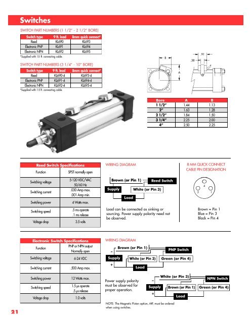
S w i t c h e s<br />
SWITCH PART NUMBERS (1 1/2” - 2 1/2” BORE)<br />
Switch type 9 ft. lead 8mm quick connect*<br />
Reed KL690 KL693<br />
Electronic PNP KL691 KL694<br />
Electronic NPN KL692 KL695<br />
*Supplied with 15 ft. connecting cable.<br />
SWITCH PART NUMBERS (3 1/4” - 10” BORE)<br />
Switch type 9 ft. lead 8mm quick connect*<br />
Reed KL690-4 KL693-4<br />
Electronic PNP KL691-4 KL694-4<br />
Electronic NPN KL692-4 KL695-4<br />
*Supplied with 15 ft. connecting cable.<br />
Re e d Sw i t c h Sp e c i f i c a t i o n s<br />
Function SPST normally open<br />
Switching voltage<br />
Switching current<br />
5-120 VDC/VAC<br />
50/60 Hz<br />
.030 Amp max.<br />
.001 Amp min.<br />
Switching power 4 Watts max.<br />
Switching speed<br />
.5 ms operate<br />
.1 ms release<br />
Voltage drop 3.5 volts<br />
El e c t ro n i c Sw i t c h Sp e c i f i c a t i o n s<br />
PNP or NPN output<br />
Function<br />
Normally open<br />
Switching voltage 6-24 VDC<br />
Switching current .500 Amp max.<br />
Switching power 12 Watts max.<br />
Switching speed<br />
1.5 µs operate<br />
.5 µs release<br />
Voltage drop 1.0 volts<br />
WIRING DIAGRAM<br />
B rown (or Pin 1)<br />
S u p p l y White (or Pin 3)<br />
–<br />
L o a d<br />
WIRING DIAGRAM<br />
B o r e A B<br />
1 1/2” 1.44 1.13<br />
2 ” 1.63 1.28<br />
2 1/2” 1.84 1.50<br />
3 1/4” 2.25 2.00<br />
4 ” 2.50 2.25<br />
Reed Switch<br />
Load can be connected as sinking or<br />
sourcing. Power supply polarity need not<br />
be observed.<br />
S u p p l y White (or Pin 3) Green (or Pin 4)<br />
+<br />
Brown (or Pin 1)<br />
Power supply polarity<br />
must be observed for<br />
proper operation.<br />
L o a d<br />
S u p p l y<br />
NOTE: The Magnetic Piston option, MP, must be ordered<br />
when using switches.<br />
–<br />
+<br />
B<br />
A<br />
PNP Switch<br />
White (or Pin 3)<br />
Brown (or Pin 1)<br />
L o a d<br />
.38<br />
8 MM QUICK CONNECT<br />
CABLE PIN DESIGNATION<br />
3<br />
.91<br />
4<br />
1<br />
Brown = Pin 1<br />
Blue = Pin 3<br />
Black = Pin 4<br />
NPN Switch<br />
Green (or Pin 4)