Watts Airline Accessories - Fluidraulics Inc
Watts Airline Accessories - Fluidraulics Inc
Watts Airline Accessories - Fluidraulics Inc

Create successful ePaper yourself
Turn your PDF publications into a flip-book with our unique Google optimized e-Paper software.
Pneumatic<br />
<strong>Airline</strong><br />
<strong>Accessories</strong><br />
Catalog WACC-01/USA
Catalog WACC-01/USA<br />
! WARNING<br />
FAILURE OR IMPROPER SELECTION OR IMPROPER USE OF THE PRODUCTS AND/OR SYSTEMS DESCRIBED<br />
HEREIN OR RELATED ITEMS CAN CAUSE DEATH, PERSONAL INJURY AND PROPERTY DAMAGE.<br />
This document and other information from Parker Hannifin Corporation, its subsidiaries and authorized distributors provide<br />
product and/or system options for further investigation by users having technical expertise. It is important that you analyze<br />
all aspects of your application including consequences of any failure, and review the information concerning the product or<br />
system in the current product catalog. Due to the variety of operating conditions and applications for these products or<br />
systems, the user, through its own analysis and testing, is solely responsible for making the final selection of the products<br />
and systems and assuring that all performance, safety and warning requirements of the application are met.<br />
The products described herein, including without limitation, product features, specifications, designs, availability and pricing,<br />
are subject to change by Parker Hannifin Corporation and its subsidiaries at any time without notice.<br />
Offer of Sale<br />
The items described in this document are hereby offered for sale by Parker Hannifin Corporation, its subsidiaries or its<br />
authorized distributors. This offer and its acceptance are governed by the provisions stated on the separate page of this<br />
document entitled “Offer of Sale”.<br />
© Copyright 2001, 2003, Parker Hannifin Corporation. All Rights Reserved<br />
Pneumatic<br />
<strong>Watts</strong> FluidAir<br />
Pneumatic Division
Catalog WACC-01/USA<br />
Index<br />
Safety Blow Guns 1-6<br />
Ball Valves, Plug Valves 1-6<br />
Lockout Valves 1-6<br />
Flow Controls & <strong>Accessories</strong> 1-20<br />
Fittings & Hose 1-12<br />
Fittings & Tubing 1-70<br />
<strong>Airline</strong> <strong>Accessories</strong> 1-4<br />
Quick Couplings & Adapters 1-16<br />
Offer of Sale<br />
Pneumatic<br />
<strong>Airline</strong> <strong>Accessories</strong><br />
Product Selection Chart<br />
<strong>Watts</strong> FluidAir<br />
Pneumatic Division<br />
A<br />
B<br />
C<br />
D<br />
E<br />
F<br />
G<br />
H
Pneumatic<br />
Brass Nozzle & Aspirator Blow Guns ......................... 2<br />
Vortec FLO-GAIN & Self Regulating Blow Guns ........ 3<br />
Button Type Brass & Pistol Grip Blow Guns ............... 4<br />
Blow Gun <strong>Accessories</strong> ............................................... 5<br />
Replacement Parts ..................................................... 6<br />
Pneumatic<br />
Safety Blow Guns<br />
Section A<br />
<strong>Watts</strong> FluidAir<br />
Pneumatic Division<br />
A
Catalog WACC-01/USA<br />
Safety Blow Guns<br />
O.S.H.A. Certification — All safety blow guns conform to the requirements of Compressed Air Standards as<br />
currently described in the U.S. Bureau of Labor Standards, paragraph 1910.242, when pressurized at the inlet<br />
to a maximum of 100 PSIG. Conform to current O.S.H.A. Directive No. 100-1.<br />
Brass Nozzle Blow Guns<br />
Contoured lever or button control both provide a natural,<br />
comfortable grip even when used with gloves. Finger<br />
guard and hang-up hook for finger protection and quick<br />
safe storage. Die cast zinc body, painted finish.<br />
Lever Operated<br />
Part Inlet SCFM<br />
Number Port Rating*<br />
00475 0010 1/4" 20<br />
Button Operated<br />
Part Inlet SCFM<br />
Number Port Rating*<br />
00470 0010 1/4" 20<br />
*Based on 100 PSIG inlet pressure.<br />
Aspirator Blow Guns<br />
Dual air shield provides wide fan of air to reduce chip<br />
blow back. Secondary shielding is provided by four radial<br />
holes for close in work. Aspirator nozzle gives heavy<br />
duty chip blowing performance without exceeding legal<br />
limits. Pressure relieves to safe limits if nozzle is blocked.<br />
Finger guard and hang-up hook offer desirable finger<br />
protection and quick secure storage. Die cast zinc body,<br />
painted finish.<br />
Lever Operated<br />
Part Inlet SCFM<br />
Number Port Rating*<br />
00475 0474 1/4" 74.5<br />
Button Operated<br />
Part Inlet SCFM<br />
Number Port Rating*<br />
00470 0474 1/4" 74.5<br />
*Based on 100 PSIG inlet pressure.<br />
Pneumatic<br />
Safety Blow Guns<br />
Brass Nozzle & Aspirator Blow Guns<br />
2<br />
<strong>Watts</strong> FluidAir<br />
Pneumatic Division
Catalog WACC-01/USA<br />
Safety Blow Guns<br />
Vortec FLO-GAIN Blow Guns<br />
A quiet Vortec FLO-GAIN nozzle is combined with a high<br />
performance blow gun. Compressed air attains sonic<br />
velocity through an adjustable slot and attaches to the<br />
exterior surface of the cone shaped nozzle. Settings are<br />
shown on a micrometer dial. Sound level of 80 dBA with<br />
80 PSIG inlet. Finger guard and hang-up hook offers<br />
desirable finger protection and quick secure storage.<br />
Die cast zinc body, painted finish.<br />
Lever Operated<br />
Part Inlet SCFM<br />
Number Port Rating*<br />
00475 0900 1/4" 70+<br />
Button Operated<br />
Part Inlet SCFM<br />
Number Port Rating*<br />
00470 0900 1/4" 70+<br />
*Based on 100 PSIG inlet pressure.<br />
Self-Regulating Blow Gun<br />
Designed with integral self-regulating pressure reducing<br />
valve for automatic shut-off when nozzle is blocked.<br />
Prevents air pressure buildup over 30 PSIG in<br />
compliance with U.S. Dept. of Labor standards.<br />
Air shield aids in protecting the operator against blow<br />
back of flying chips of dirt. Designed to operate at less<br />
than 90 dBA to comply with government regulations.<br />
Die cast zinc body, painted finish.<br />
May be used with nozzle extensions on Page 5.<br />
Ordering Information<br />
Part Inlet SCFM<br />
Number Port Rating*<br />
00475 2900 1/4" 10<br />
Performance Data<br />
Inlet Blocked Sound<br />
Pressure Pressure Level<br />
70 PSIG 17.0 PSIG 79 dBA<br />
100 PSIG 21.0 PSIG 83 dBA<br />
175 PSIG 28.0 PSIG 87 dBA<br />
*Based on 100 PSIG inlet pressure.<br />
Pneumatic<br />
Safety Blow Guns<br />
Vortec FLO-GAIN & Self Regulating Guns<br />
3<br />
<strong>Watts</strong> FluidAir<br />
Pneumatic Division<br />
A
Catalog WACC-01/USA<br />
Safety Blow Guns<br />
Button Type Brass Blow Gun<br />
These general purpose blow guns are ideal for almost<br />
any cleaning purpose. Their drop forged brass bodies<br />
provide strength and long life. Corrosion resistant parts.<br />
May be used for spraying many light liquids. Available<br />
with standard brass nozzle.<br />
Part Inlet SCFM<br />
Number Port Rating*<br />
07184 1000 1/4" 20<br />
*Based on 100 PSIG inlet pressure.<br />
Pistol Grip Blow Gun<br />
Pistol grip is easy to aim for quick and efficient<br />
cleaning. Ideal for all shop housekeeping purposes.<br />
Lightweight and easy to handle. Easy trigger action<br />
features instant spring adjustment for controlled air.<br />
Get the amount of air where you want it with no<br />
restrictions, no cut-offs! Makes for a convenient<br />
connection for overhead or underbench floor<br />
air use.<br />
Part Inlet SCFM<br />
Number Port Rating*<br />
BG441-NBL 1/4" 11.0<br />
*Based on 100 PSIG inlet pressure.<br />
Pneumatic<br />
Safety Blow Guns<br />
Button Type Brass & Pistol Grip Blow Guns<br />
4<br />
<strong>Watts</strong> FluidAir<br />
Pneumatic Division
Catalog WACC-01/USA<br />
Blow Gun <strong>Accessories</strong><br />
Brass Nozzle<br />
Model No. 00470 7020<br />
General purpose nozzles are supplied as standard on<br />
00470 0010, 00475 0010 and 07184 1000 blow guns.<br />
Conform to the requirements of the Williams Steiger<br />
Occupational Safety and Health Act of 1970, paragraph<br />
1910.242 when fitted with blow guns pressurized at the<br />
inlet to a maximum of 100 PSIG. Conform to O.S.H.A.<br />
Directive 100-1.<br />
Aspirator Nozzle<br />
Model No. 00474 1000<br />
Protect against personal injury by relieving pressure if the<br />
nozzle end is blocked. Develop exceptionally high flow<br />
rates which insure effective cleaning. Conform to the<br />
requirements of the Williams Steiger Occupational Safety<br />
and Health Act of 1970, paragraphs 1910.95 and<br />
1910.242 when fitted with blow guns pressurized at the<br />
inlet to a maximum of 100 PSIG. Conform to O.S.H.A.<br />
Directive 100-1.<br />
FLO-GAIN Nozzle<br />
Model No. W1110 0900<br />
This FLO-GAIN nozzle is the most widely used of the<br />
transvector products for industrial blow off. Compressed<br />
air attains sonic velocity through an adjustable slot and<br />
attaches to the cone shaped exterior surface of the nozzle.<br />
Induction and entrainment take place outside the nozzle.<br />
Factory slot setting is .008 inch, but is adjustable from<br />
closed to .012 inch. A micrometer dial allows adjustment<br />
without the use of shims or gauges.<br />
Must be used with filtered air.<br />
Pneumatic<br />
Safety Blow Guns<br />
Conform to O.S.H.A.<br />
5<br />
U.S. Patent No. 3,647,142<br />
<strong>Watts</strong> FluidAir<br />
Pneumatic Division<br />
A
Catalog WACC-01/USA<br />
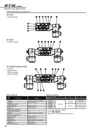
Replacement Parts<br />
470 and 475 Series Blow Guns<br />
00470 0100 Plunger Unit<br />
(For Button Models)<br />
00470 8003 Plunger Assembly<br />
(For Lever Models)<br />
* Contained in Service Kit No. 00470 0090<br />
Button Type Brass Blow Gun<br />
† Contained in Plunger Unit 07184 8000<br />
* Contained in Service Kit No. 07184 8001<br />
Pneumatic<br />
Nose<br />
00470 7020<br />
†Plunger<br />
†Nut<br />
†*O-ring<br />
†*Rubber Washer<br />
O-Ring<br />
Nut<br />
Deflator<br />
*Washer<br />
*Spring<br />
00470 7020 Nose<br />
Safety Blow Guns<br />
470, 475, Button Type & Spray Nozzle<br />
6<br />
†Retaining Ring<br />
†Spring<br />
Made in England<br />
<strong>Watts</strong> FluidAir<br />
Pneumatic Division
Pneumatic<br />
Ball Valve Basic Features ..........................................2<br />
Ball Valve Part Numbers & Dimensions ................. 3-4<br />
Plug Valve Basic Features .........................................5<br />
Plug Valve Part Numbers & Dimensions....................6<br />
Pneumatic<br />
Ball Valves<br />
1/4" to 2", 2-Way<br />
1/4" to 1", 2-Way Vented<br />
Plug Valves<br />
1/8" to 1/4" Pipe Size<br />
Section B<br />
<strong>Watts</strong> FluidAir<br />
Pneumatic Division<br />
B
Catalog WACC-01/USA<br />
Basic Features & Specifications<br />
Advantages<br />
Parker’s forged body ball valve provides extended<br />
service life and resists failure caused by severe<br />
temperature applications. Optimum flow design assures<br />
maximum system efficiency. Highly inert PTFE seats<br />
and seals provide resistance to chemical corrosion.<br />
Parker also provides a blow-out proof stem, chrome<br />
plated brass ball and a specially designed handle<br />
enabling increased turning leverage for ease of opening<br />
and closing. Parker’s ball valve can be readily identified<br />
assuring high quality engineering and reliability. This<br />
economical ball valve is available in female pipe sizes.<br />
Parker’s ball valve bodies are machined from high<br />
quality CA 377 forgings.<br />
Applications<br />
Parker's industrial ball valve product line is intended for<br />
general purpose use. Please be aware that ball valves<br />
are intended for use in the fully open or closed positions.<br />
Depending on application conditions, throttling of the<br />
valve may result in premature seal failure and/or inability<br />
to turn the valve handle.<br />
For use as fuel line shutoffs for gasoline and diesel<br />
powered over the highway, off highway, and construction<br />
equipment vehicles. Water and air service lines on<br />
capital equipment and plant design plumbing that<br />
require total shutoff capability.<br />
Working Pressure and Temperature<br />
Saturated steam service up to 150 PSI and 400°F<br />
Vacuum, 29 <strong>Inc</strong>hes of Mercury<br />
Vented up to 250 PSI<br />
PRESSURE (PSI)<br />
600<br />
450<br />
300<br />
150<br />
1/4 to 1 <strong>Inc</strong>h<br />
1-1/4 to 2 <strong>Inc</strong>h<br />
Pneumatic<br />
Ball Valves<br />
Series 500<br />
Brass Ball Valves Series 500<br />
0<br />
0 50 100 150 200 250 300 350<br />
TEMPERATURE (˚F)<br />
2<br />
Operating Instructions<br />
Quarter turn is “ON” or “OFF”.<br />
(Provides positive stop action for full shutoff.)<br />
NOTE: PERIODICALLY CHECK THE ADJUSTABLE<br />
PACKING NUT AND TIGHTEN AS REQUIRED.<br />
Style Type Material Size<br />
V 500<br />
V – Valve<br />
P - 4<br />
Style<br />
VP – Valve, Padlocking Handle<br />
VV – Valve, Vented<br />
VVP – Valve, Vented, Padlocking Handle<br />
Type 500 – Female/Female PTF Ports<br />
Material P – Brass<br />
4 – 1/4"<br />
6 – 3/8"<br />
Size 8 – 1/2"<br />
12 – 3/4"<br />
16 – 1"<br />
Style Type Material Size<br />
V 500 P - 20<br />
Style<br />
V – Valve<br />
VP – Valve, Padlocking Handle<br />
Type 500 – Female/Female PTF Ports<br />
Material P – Brass<br />
20 – 1-1/4"<br />
Size 24 – 1-1/2"<br />
32 – 2"<br />
Flow Data<br />
Valve Size C V<br />
1/4 4.0<br />
3/8 5.8<br />
1/2 12.0<br />
3/4 35.0<br />
1 54.0<br />
1-1/4 57.0<br />
1-1/2 92.0<br />
2 224.0<br />
<strong>Watts</strong> FluidAir<br />
Pneumatic Division
Catalog WACC-01/USA<br />
Part Numbers & Dimensions<br />
V500P Female-Female Pipe Ends<br />
Pneumatic<br />
Ball Valves<br />
Series 500<br />
Part<br />
Pipe<br />
Thread B C Flow<br />
No. [PTF] Hex Hex H L M N Dia. D<br />
V500P-4 1/4 15/16 15/16 3.96 4.90 2.03 2.47 .375<br />
V500P-6 3/8 15/16 15/16 3.96 4.90 2.03 2.47 .375<br />
V500P-8 1/2* 1-1/16 1-1/16 3.96 5.00 2.20 2.58 .500<br />
V500P-12 3/4** 1-1/4 1-5/16 3.96 5.25 2.42 2.81 .685<br />
V500P-16 1** 1-1/2 1-9/16 3.96 5.34 2.75 3.08 .875<br />
*PTF special short<br />
**PTF special extra short<br />
V500P-20, V500P-24, V500P-32 Female-Female Pipe Ends<br />
Part<br />
No.<br />
Pipe<br />
Thread<br />
[PTF]<br />
Octagon H L M N Dia. D<br />
V500P-20 1-1/4 1.93 6.22 8.05 3.66 3.01 1.18<br />
V500P-24 1-1/2 2.13 6.22 8.23 4.02 3.25 1.50<br />
V500P-32 2 2.69 6.22 8.58 4.76 3.52 1.89<br />
VV500P Vented, Female Pipe Ends<br />
Part<br />
No.<br />
Pipe<br />
Thread<br />
[PTF]<br />
B<br />
Hex<br />
C<br />
Hex<br />
K H L M N<br />
Flow<br />
Dia. D<br />
VV500P-4 1/4 15/16 15/16 1.11 3.96 4.90 2.03 2.47 .375<br />
VV500P-6 3/8 15/16 15/16 1.11 3.96 4.90 2.03 2.47 .375<br />
VV500P-8 1/2* 1-1/16 1-1/16 1.23 3.96 5.00 2.20 2.58 .500<br />
VV500P-12 3/4** 1-1/4 1-5/16 1.45 3.96 5.25 2.42 2.81 .685<br />
VV500P-16 1** 1-1/2 1-9/16 1.58 3.96 5.34 2.75 3.08 .875<br />
*PTF special short<br />
**PTF special extra short<br />
3<br />
C HEX<br />
D<br />
C Octagon<br />
C HEX<br />
K<br />
M<br />
M<br />
M<br />
H<br />
H<br />
L<br />
B HEX<br />
D<br />
L<br />
L<br />
H<br />
B HEX<br />
D<br />
<strong>Watts</strong> FluidAir<br />
Pneumatic Division<br />
B Octagon<br />
10-32 UNF-2B<br />
N<br />
N<br />
N<br />
B
Catalog WACC-01/USA<br />
Part Numbers & Dimensions<br />
VP500P Locking Handle, Female Pipe Ends<br />
Pneumatic<br />
Ball Valves<br />
Series 500<br />
Part Pipe B C Flow<br />
No. Thread Hex Hex H L M N Dia. D<br />
VP500P-4 1/4 15/16 15/16 3.96 4.90 2.03 2.47 .375<br />
VP500P-6 3/8 15/16 15/16 3.96 4.90 2.03 2.47 .375<br />
VP500P-8 1/2* 1-1/16 1-1/16 3.96 5.00 2.20 2.58 .500<br />
VP500P-12 3/4** 1-1/4 1-5/16 3.96 5.25 2.42 2.81 .685<br />
VP500P-16 1** 1-1/2 1-9/16 3.96 5.34 2.75 3.08 .875<br />
For use with 5/16" Dia. shank lock; .33 Dia.<br />
VP500P-20 1-1/4 1-15/16 1-15/16 6.22 8.05 3.66 4.04 1.180<br />
VP500P-24 1-1/2 2-1/8 2-1/8 6.22 8.23 4.02 4.52 1.500<br />
VP500P-32 2 2-11/16 2-11/16 6.22 8.60 4.76 5.07 1.890<br />
For use with 9/32" Dia. shank lock; .31 Dia.<br />
* PTF special short<br />
**PTF special extra short<br />
4<br />
C HEX<br />
VVP500 POSHA 29 CFR Part 1910 Vented, Locking Handle, Female Pipe Ends<br />
Part Pipe B C Flow<br />
No. Thread Hex Hex K H L M N Dia. D<br />
VVP500P-4 1/4 15/16 15/16 1.11 3.96 4.90 2.03 2.47 .375<br />
VVP500P-6 3/8 15/16 15/16 1.11 3.96 4.90 2.03 2.47 .375<br />
VVP500P-8 1/2* 1-1/16 1-1/16 1.23 3.96 5.00 2.20 2.58 .500<br />
VVP500P-12 3/4** 1-1/4 1-5/16 1.45 3.96 5.25 2.42 2.81 .685<br />
VVP500P-16 1** 1-1/2 1-9/16 1.58 3.96 5.34 2.75 3.08 .875<br />
For use with 5/16" Dia. shank lock<br />
* PTF special short<br />
**PTF special extra short<br />
C HEX<br />
K<br />
M<br />
M<br />
H<br />
H<br />
.33Ø<br />
L<br />
ON<br />
OFF<br />
B HEX<br />
D<br />
L<br />
ON<br />
OFF<br />
B HEX<br />
D<br />
10-32 UNF-2B<br />
(All Sizes)<br />
<strong>Watts</strong> FluidAir<br />
Pneumatic Division<br />
N<br />
N
Catalog WACC-01/USA<br />
Basic Features & Specifications<br />
Advantages<br />
Compact design features internal nitrile seals and a<br />
one-piece extruded brass body, offering compatibility with<br />
a wide range of media. The one-piece stem/handle<br />
combination is constructed of glass reinforced acetal<br />
copolymer. Parker plug valves feature 1/4 turn shutoff<br />
allowing for ease of operation. All plug valves are 100%<br />
leak tested and are certified to be leak free to one SCCM.<br />
Materials<br />
Extruded Bodies: CA 360<br />
Stem/Handle: Acetal Copolymer<br />
O-Rings: Nitrile (other compounds available)<br />
Stop Pin: 420SS<br />
Spiral Ring: 302SS<br />
Temperature and Working<br />
Pressure Ranges<br />
From -40° to +175°F at 250 PSI maximum.<br />
Pneumatic<br />
Plug Valves<br />
1/8" to 1/4" Pipe<br />
Plug Valves Series PV<br />
Applications<br />
Manufactured for use with air, water, oil and certain other<br />
fluids. Contact factory for special fluid requirements.<br />
Installation Instructions<br />
To assure sealability and reliable performance, the valve<br />
must be installed so that the flow media travels in the<br />
direction of the arrow on the valve handle.<br />
5<br />
Order<br />
By part number and name.<br />
Nomenclature<br />
Part numbers are constructed from symbols that identify<br />
the style and size of the fitting. The first series of<br />
numbers and letters identifies the style and type fitting.<br />
The second series of numbers describes the size.<br />
Features<br />
Example:<br />
PV 607 - 2<br />
Plug Valve<br />
Male to Male<br />
1/8" (2/16) Male<br />
420 Stainless Steel<br />
Stopping Pin<br />
Acetal copolymer<br />
reinforced for strength<br />
highly compatible with<br />
most media<br />
Triple O-Ring Seal<br />
Extruded Brass<br />
Body (CA360)<br />
302<br />
Stainless<br />
Steel Clip<br />
<strong>Watts</strong> FluidAir<br />
Pneumatic Division<br />
B
Catalog WACC-01/USA<br />
Part Numbers & Dimensions<br />
Male Pipe to Male Pipe Plug Valve PV607<br />
Pneumatic<br />
Plug Valves<br />
1/8" to 1/4" Pipe<br />
Part<br />
No.<br />
Pipe<br />
Thread<br />
H L M N N1<br />
Flow<br />
Dia. D<br />
PV607-2 1/8 .67 1.34 1.66 1.38 .51 .200<br />
PV607-4 1/4 .67 1.34 2.02 1.38 .51 .200<br />
PV608 Female Pipe to Male Pipe Plug Valve<br />
Part<br />
No.<br />
Pipe<br />
Thread<br />
H L M N N1<br />
Flow<br />
Dia. D<br />
PV608-2 1/8 .67 1.34 1.67 1.38 .51 .200<br />
PV608-4 1/4 .67 1.34 2.06 1.38 .51 .200<br />
PV609 Female Pipe to Female Pipe Plug Valve<br />
Part<br />
No.<br />
Pipe<br />
Thread<br />
H L M N N1<br />
Flow<br />
Dia. D<br />
PV609-2 1/8 .67 1.34 1.68 1.38 .51 .200<br />
PV609-4 1/4 .67 1.34 2.10 1.38 .51 .200<br />
6<br />
D<br />
D<br />
D<br />
L<br />
M<br />
L<br />
M<br />
M<br />
L<br />
H<br />
H<br />
H<br />
N1<br />
N1<br />
N1<br />
N<br />
N<br />
N<br />
<strong>Watts</strong> FluidAir<br />
Pneumatic Division
Pneumatic<br />
“LV” Series<br />
Basic Features .......................................................2<br />
Applications ............................................................2<br />
Mounting ................................................................2<br />
Dimensions ............................................................2<br />
“LV” Series Technical Information<br />
Operation ...............................................................3<br />
Specifications .........................................................3<br />
Ordering Information ..............................................3<br />
Pneumatic<br />
Lockout Valves<br />
Section C<br />
“EZ” Series<br />
Basic Features .......................................................4<br />
Applications ............................................................4<br />
Mounting ................................................................4<br />
Dimensions ............................................................4<br />
“EZ” Series Technical Information<br />
Operation ...............................................................5<br />
Specifications .........................................................5<br />
Ordering Information ..............................................5<br />
Flow & Safety Standards............................................ 6<br />
<strong>Watts</strong> FluidAir<br />
Pneumatic Division<br />
C
Catalog WACC-01/USA<br />
Basic Features<br />
“LV” Series<br />
Features<br />
Used in systems for compliance with<br />
OSHA Standard 29 CFR Part 1910<br />
1/4 inch to 1-1/4 inch Pipe Sizes<br />
Cv’s from 3.0 to 14<br />
1 and 1-1/4 inch Exhaust Ports available<br />
Rugged Cast Aluminum Alloy Body<br />
Metal Handle Offered in 1" Exhaust Port<br />
Sizes; Plastic Handle Offered in 1-1/4"<br />
Exhaust Port Sizes<br />
Inline or Surface Mountable<br />
Safety Yellow and Red for High Visibility<br />
Detented Spool<br />
Exhaust Port Threaded for Installation of<br />
Silencer or Line for Remote Exhausting<br />
Applications<br />
Lockout valves are installed in pneumatic drop legs,<br />
or individual pneumatic control lines (see Figure 1).<br />
In accordance with OSHA procedures, lockout valves<br />
are used during maintenance and service procedures<br />
of pneumatically (air) operated equipment. Prior to<br />
servicing, the red handle is pressed inward, blocking<br />
pressure and relieving all downstream air pressure.<br />
A padlock is installed through the locking hasp,<br />
Preventing accidental actuation during the<br />
maintenance procedure. Following maintenance,<br />
the padlock is removed and the red handle is pulled<br />
outward, returning air pressure to the system.<br />
(For complete Lockout / Tagout procedures, consult<br />
OSHA Standard 29 CFR Part 1910 in U.S. Federal<br />
Register/Vol. 54 No. 169, Friday, September 1, 1989 /<br />
Page 36644.)<br />
Mounting<br />
Valves can be inline mounted or surface mounted<br />
using the two 11/32" mounting holes provided in the<br />
valve body. Mount valves in plain view with the handle<br />
oriented for accessibility.<br />
Pneumatic<br />
“LV” Series, Lockout Valve<br />
Applications & Dimensions<br />
2<br />
3<br />
1<br />
12<br />
10<br />
2<br />
Dimensions<br />
L<br />
K<br />
Inlet Outlet<br />
1 2<br />
E<br />
D<br />
F<br />
3<br />
Exhaust<br />
J<br />
A<br />
H<br />
G<br />
LV Series, 1" Exhaust Port <strong>Inc</strong>hes (mm)<br />
.34 Dia. Thru<br />
2 Places<br />
LV Series Valve shown with optional ES Series Silencer. For more<br />
information refer to Section D.<br />
A B C D E F<br />
8.34 5.64 6.65 2.21 1.10 2.94<br />
(212) (143) (169) (56) (28) (75)<br />
G H J K L<br />
4.14 1.32 1.55 .69 2.00<br />
(105) (34) (39) (18) (51)<br />
LV Series, 1-1/4" Exhaust Port <strong>Inc</strong>hes (mm)<br />
A B C D E F<br />
7.32 6.63 7.63 2.74 1.37 3.95<br />
(186) (168) (194) (70) (35) (100)<br />
G H J K L<br />
5.50 1.74 1.92 1.00 2.26<br />
(140) (44) (49) (25) (57)<br />
<strong>Watts</strong> FluidAir<br />
Pneumatic Division<br />
B<br />
C
Catalog WACC-01/USA<br />
Technical Information<br />
Operation<br />
Normal Machine Operation – Valve Open<br />
With the handle pulled outward. Inlet Port 1 is open to<br />
outlet Port 2. Exhaust Port 3 is blocked.<br />
Specifications<br />
Open<br />
Operating Pressure Range<br />
0 to 250 PSIG (0 to 1725 kPa)<br />
Operating Temperature Range (Ambient)<br />
32°F to 160°F (0°C to 71°C)<br />
Lubrication<br />
For best results and service life, use clean, moisture<br />
free, lubricated air.<br />
Recommended Lubricant<br />
F442 Oil<br />
LV Series Model Number Index<br />
† Trademark Magnalube<br />
Pneumatic<br />
Port Size<br />
(Inlet & Outlet<br />
Ports 1 & 2)<br />
2 1/4" *<br />
3 3/8" *<br />
4 1/2" *<br />
6 3/4" * ‡<br />
8 1" * ‡<br />
A 1-1/4" ‡<br />
* Available with<br />
1" Exhaust Port.<br />
‡ Available with<br />
1-1/4" Exhaust<br />
Port.<br />
“LV” Series, Lockout Valve<br />
Operation, Specifications & Ordering Info<br />
Basic Port Thread Design Port<br />
Series Size Type Level Size<br />
LV 6 N A A<br />
Thread Type<br />
(Ports 1, 2 & 3)<br />
N NPT<br />
B BSPP (G)<br />
R BSPT (R)<br />
3<br />
Lockout Operation – Valve Closed<br />
With the handle pushed inward. Inlet Port 1 is blocked.<br />
Outlet Port 2 is open to Exhaust Port 3.<br />
Design Level<br />
A Current<br />
Closed<br />
Materials of Construction<br />
Body: Cast Aluminum Alloy<br />
Handle: 1" Exhaust Port - Cast Aluminum Alloy<br />
1-1/4" Exhaust Port - Plastic<br />
Spool: Aluminum<br />
Seals: Carboxylated Nitrile<br />
Detent Spring: Stainless Steel<br />
Grease: Magnalube G †<br />
Port Size<br />
(Exhaust<br />
Port 3)<br />
8 1"<br />
A 1-1/4"<br />
<strong>Watts</strong> FluidAir<br />
Pneumatic Division<br />
C
Catalog WACC-01/USA<br />
Basic Features<br />
“EZ” Series<br />
Features<br />
Combines Lockout and Soft-Start<br />
Functions in a Single Unit<br />
Used in systems for compliance with<br />
OSHA Standard 29 CFR Part 1910<br />
3/8 inch to 1-1/4 inch Pipe Sizes<br />
Cv’s from 3.7 to 13.7<br />
3/4 and 1-1/4 inch: Exhaust Ports available<br />
Rugged Cast Aluminum Alloy Body<br />
Exhaust Port Threaded for Installation of<br />
Silencer or Line for Remote Exhausting<br />
Inline or Surface Mountable<br />
Applications<br />
EZ valves are installed in pneumatic drop legs,<br />
or individual pneumatic control lines (see Figure 1).<br />
In accordance with OSHA procedures, EZ valves are<br />
used during maintenance and service procedures of<br />
pneumatically (air) operated equipment. Prior to<br />
servicing, the blue handle is pressed inward, blocking<br />
pressure and relieving all downstream air pressure.<br />
A padlock is installed through the locking hasp,<br />
preventing accidental actuation during the<br />
maintenance procedure. Following maintenance,<br />
the padlock is removed and the blue handle is pulled<br />
outward, gradually returning air pressure to the<br />
system. (For complete Lockout / Tagout procedures,<br />
consult OSHA Standard 29 CFR Part 1910 in U.S.<br />
Federal Register/Vol. 54 No. 169, Friday, September 1,<br />
1989 /Page 36644.)<br />
Mounting<br />
Valves can be inline mounted or surface mounted<br />
using the two 11/32" mounting holes provided in the<br />
valve body. Mount valves in plain view with the handle<br />
oriented for accessibility.<br />
Pneumatic<br />
“EZ” Series, Lockout Valve<br />
Applications & Dimensions<br />
4<br />
Dimensions<br />
K<br />
Inlet Outlet<br />
1 2<br />
E<br />
D<br />
F<br />
L<br />
EZ Series Valve shown with optional ES Series Silencer. For more<br />
information refer to Section D.<br />
J<br />
H<br />
G<br />
A<br />
.34 Dia. Thru<br />
2 Places<br />
EZ Series, 3/4" Exhaust Port <strong>Inc</strong>hes (mm)<br />
EZ Series, 1-1/4" Exhaust Port <strong>Inc</strong>hes (mm)<br />
<strong>Watts</strong> FluidAir<br />
Pneumatic Division<br />
3<br />
Exhaust<br />
A B C D E F<br />
6.26 5.78 6.25 2.20 1.10 2.97<br />
(159) (147) (159) (56) (28) (75)<br />
G H J K L<br />
4.36 1.32 1.44 .80 2.02<br />
(111) (34) (37) (20) (51)<br />
A B C D E F<br />
7.32 6.63 7.63 2.74 1.37 3.95<br />
(186) (168) (194) (70) (35) (100)<br />
G H J K L<br />
5.50 1.74 1.92 1.00 2.26<br />
(140) (44) (49) (25) (57)<br />
1<br />
3<br />
12<br />
10<br />
B<br />
C<br />
2
Catalog WACC-01/USA (Revised 10/25/04)<br />
Technical Information<br />
Operation<br />
Normal Machine Operation – Valve Open<br />
When the blue handle is pulled outward, the adjustable<br />
needle valve (accessed through the top of the handle)<br />
setting determines the rate of pressure buildup. When<br />
downstream pressure reaches the full flow described<br />
in the specifications below, Inlet Port 1 is open to<br />
outlet Port 2. Exhaust Port 3 is blocked.<br />
Specifications<br />
Operating Pressure Range<br />
30 to 150 PSIG (2 to 10 bar)<br />
Open to Full Flow: Inlet Pressure - 25 PSIG (1.7 bar)<br />
Operating Temperature Range (Ambient)<br />
40°F to 175°F (4°C to 80°C)<br />
Lubrication<br />
For best results and service life, use clean, moisture<br />
free, lubricated air.<br />
Pneumatic<br />
“EZ” Series, Lockout Valve<br />
Operation, Specifications & Ordering Info<br />
5<br />
Lockout Operation – Valve Closed<br />
When the blue handle is pushed inward, the Inlet<br />
Port 1 is blocked. Downstream air is exhausted<br />
through Exhaust Port 3.<br />
Recommended Lubricant<br />
F442 Oil<br />
Materials of Construction<br />
Body: Cast Aluminum Alloy<br />
Handle: Plastic<br />
Spool: Aluminum<br />
Seals: Carboxylated Nitrile<br />
Detent Spring: Stainless Steel<br />
Grease: Magnalube G †<br />
EZ Combination EEZ-On Series Model Number Index<br />
Notes:<br />
* Available with<br />
3/4" Exhaust Port.<br />
‡ Available with<br />
1-1/4" Exhaust Port.<br />
† Trademark Magnalube<br />
Open<br />
Pressure Building Up<br />
Open<br />
Full Flow<br />
Port Size<br />
(Inlet & Outlet<br />
Ports 1 & 2)<br />
03 3/8" *<br />
04 1/2" *<br />
06 3/4" * ‡<br />
08 1" ‡<br />
0A 1-1/4" ‡<br />
Closed<br />
Basic Port Thread Design Port<br />
Series Size Type Level Size<br />
EZ 03 N B A<br />
Thread Type<br />
(Ports 1, 2 & 3)<br />
N NPT<br />
B BSPP (G)<br />
R BSPT (R)<br />
Design Level<br />
B Current<br />
Port Size<br />
(Exhaust<br />
Port 3)<br />
6 3/4"<br />
A 1-1/4"<br />
<strong>Watts</strong> FluidAir<br />
Pneumatic Division<br />
C
Catalog WACC-01/USA (Revised 10/25/04)<br />
Technical Information<br />
Flow<br />
Model 1 to 2 Cv 2 to 3 Cv<br />
LV2NA8 3.00 6.00<br />
LV3NA8 4.30 9.00<br />
LV4NA8 7.70 11.30<br />
LV6NA8 9.50 9.00<br />
LV6NAA 13.98 10.90<br />
LV8NA8 10.20 8.80<br />
LV8NAA 16.70 9.86<br />
LVANAA 19.71 10.41<br />
Schematic<br />
Main Air<br />
Pressure<br />
Friday, September 1, 1989 the Occupational Safety and<br />
Health Administration (OSHA) passed a standard,<br />
29CFR Part 1910, requiring certain lockout and / or<br />
tagout procedures for the control of a hazardous energy<br />
source. This standard addresses practices and<br />
procedures that are necessary to disable the release of<br />
potentially hazardous energy while maintenance and<br />
servicing activities are being performed. Tagout refers to<br />
the use of tags to warn workers when equipment using<br />
potentially hazardous energy is being serviced. Lockout<br />
is the procedure which ensures that all power to a piece<br />
of equipment is isolated, locked or blocked and<br />
dissipated using a method that cannot be readily<br />
removed to bypassed. Dissipation means stored energy<br />
at the equipment is brought to a neutral state. This<br />
standard is expected to save 120 lives and prevent<br />
60,000 accidents a year. This OSHA Standard became<br />
effective October 31, 1989.<br />
Pneumatic<br />
3<br />
1<br />
12<br />
10<br />
2<br />
FRL<br />
“EZ” & “LV” Series, Lockout Valves<br />
Flow & Safety Standards<br />
Figure 1<br />
Lockout Valves Shown In The<br />
Passing Condition<br />
6<br />
Model 1 to 2 Cv 2 to 3 Cv<br />
EZ03NB6 3.79 3.78<br />
EZ04NB6 5.31 3.77<br />
EZ06NBA 6.01 9.25<br />
EZ08NBA 11.18 8.13<br />
EZ0ANBA 13.74 8.03<br />
3<br />
1<br />
12<br />
10<br />
To<br />
Requirement<br />
2<br />
To<br />
Requirement<br />
A typical application (Figure 1) shows a main lockout<br />
valve mounted in the main drop leg, before the split to<br />
machine functions. Additional lockout valves can be used<br />
to isolate individual control lines. Before servicing, the<br />
valve can be actuated and locked to isolate downstream<br />
from pressure, and exhaust downstream to atmosphere<br />
thus making equipment safe for maintenance.<br />
To reference this standard see the U.S. Federal Register<br />
/ Vol. 54, No. 169 / Friday, September 1, 1989 / Page<br />
36644. For copies of this standard, contact U.S.<br />
Department of Labor, Occupational Safety and Health<br />
Administration, Office of Publication, Room N3101,<br />
Washington, DC 20210, (202) 523-9667.<br />
<strong>Watts</strong> FluidAir<br />
Pneumatic Division
Pneumatic<br />
Flow Control Valves<br />
“SPF” Series ..........................................................2<br />
“337” Series ...........................................................3<br />
“3250” Series ..................................................... 4-5<br />
Right Angle Series ............................................. 6-9<br />
Needle Valves<br />
“SPN” Series ........................................................10<br />
“338” Series .........................................................11<br />
“SPC” Series Check Valve ...................................12<br />
Pneumatic<br />
Flow Controls<br />
& <strong>Accessories</strong><br />
Section D<br />
“339” & “3047” Series Check Valve ..................... 13<br />
“EM” Series Exhaust Mufflers .............................. 14<br />
Breather Vents ..................................................... 15<br />
“ES” Series Silencer............................................. 15<br />
ASN Air Line Silencer .......................................... 16<br />
Muffler-Reclassifier ECS ...................................... 17<br />
Automatic Drip Leg Drain .....................................18<br />
Relief Valves ........................................................ 18<br />
Quick Exhaust & Shuttle Valves .................... 19-21<br />
<strong>Watts</strong> FluidAir<br />
Pneumatic Division<br />
D
Catalog WACC-01/USA<br />
Flow Control Valves<br />
Component Materials<br />
Body Material: Brass<br />
Needle: Stainless Steel<br />
Ball Check: Stainless Steel<br />
Check Retainer: Acetal<br />
Needle Seals: Nitrile (Standard),<br />
Fluorocarbon (Optional)<br />
Knob: Aluminum<br />
Pneumatic<br />
D<br />
E C<br />
F<br />
B<br />
(Open)<br />
A<br />
(Both Ends)<br />
Model Selection and Dimensions<br />
For units with Fluorocarbon seals, add suffix “V”. Example: SPF200BV<br />
Flow Controls & <strong>Accessories</strong><br />
“SPF” Series – 1/8" to 1/2" Ports<br />
2<br />
General Information<br />
The “SPF” Series Flow Control Valves meter flow of<br />
air or oil in one direction and allow free flow in the<br />
reverse direction.<br />
“SPF” Series valves are manufactured with a two step<br />
needle. Fine metering is accomplished over the initial<br />
adjustment turns and nominal metering is provided<br />
over the remaining turns. Once the desired flow is<br />
selected, a set screw can be tightened to maintain the<br />
setting.<br />
These valves are available with NPTF ports in 1/8",<br />
1/4", 3/8", and 1/2" sizes.<br />
Valve Specifications<br />
Maximum Operating Pressure<br />
2000 PSI Non-Shock<br />
Cracking pressure for return check poppet –<br />
5 PSI Nominal<br />
Operating Temperature<br />
Standard: 0° to 140° F*<br />
-40° to 140° F (Hydraulic service)<br />
Extended Temperature: 0° to 400°F*<br />
* Ambient temperatures below freezing require moisture-free air.<br />
Ambient temperatures below freezing and above 180° require<br />
lubricants especially selected for suitability at these<br />
temperatures. Pneumatic valves should be used with filtered<br />
and lubricated air.<br />
Model<br />
Number<br />
A Port Size B C D E F<br />
SPF200B 1/8-27 NPTF 1.50 1.75 .625 1.06 .75<br />
SPF400B 1/4-18 NPTF 1.80 2.38 .812 1.41 .81<br />
SPF600B 3/8-18 NPTF 2.25 2.75 1.000 1.75 1.00<br />
SPF800B 1/2-14 NPTF 2.72 3.19 1.250 2.06 1.19<br />
Performance Data - Flow<br />
Controlled Flow Free Flow<br />
Needle Full Open/Check Closed Needle Full Open<br />
Model Flow - SCFM Effective Flow - SCFM Effective<br />
Number @ 100 PSI<br />
Full DP<br />
Cv Area<br />
Sq. <strong>Inc</strong>hes<br />
@ 100 PSI<br />
Full DP<br />
Cv Area<br />
Sq. <strong>Inc</strong>hes<br />
SPF200B 8.8 .16 .006 25.4 .46 .018<br />
SPF400B 19.3 .35 .013 55.2 1.00 .038<br />
SPF600B 33.1 .60 .023 99.3 1.80 .070<br />
SPF800B 55.2 1.00 .038 138.0 2.50 .096<br />
<strong>Watts</strong> FluidAir<br />
Pneumatic Division
Catalog WACC-01/USA<br />
Micrometer Flow Control Valves<br />
Body Material: Brass<br />
Needle: Stainless Steel<br />
Check Seal: Urethane<br />
Needle Seals: Buna N<br />
(Fluorocarbon optional –<br />
consult factory)<br />
C<br />
Model Selection and Dimensions<br />
Pneumatic<br />
B<br />
DIA.<br />
Knob: Aluminum<br />
Spring: Stainless Steel<br />
Retainer: Zinc- Plated Steel<br />
Set Screw: Steel<br />
Flow Controls & <strong>Accessories</strong><br />
“337” Series – 1/8" to 3/4" Ports<br />
Port Flow (SCFM†) Dimensions Service<br />
Size Model Adj. Free Flow A B C H1 H2 Kit<br />
1/8" 00337 1000 15 32 9/16" 0.75 1.47 2.03 1.81 00337 8000<br />
1/4" 00337 1001 28 75 11/16" 0.75 1.47 2.28 2.03 00337 8001<br />
3/8" 00337 1002 59 139 7/8" 0.88 2.31 2.84 2.53 00337 8002<br />
1/2" 00337 1003 126 183 1-3/16" 1.06 3.25 3.62 3.22 00337 8003<br />
3/4" 00337 1004 140 327 1-3/8" 1.06 3.25 3.72 3.31 00337 8004<br />
† At 100 PSIG inlet pressure with full pressure drop.<br />
Mounting Bracket Model Selection<br />
and Dimensions<br />
1<br />
1<br />
0 9<br />
Component Materials<br />
A<br />
H1 - OPEN<br />
H2 - CLOSED<br />
A<br />
3<br />
General Information<br />
The “337” Series Flow Control Valves meter flow<br />
of air in one direction and allow free flow in the<br />
reverse direction.<br />
The “337” Series valves are manufactured with a fine<br />
tapered needle providing precise flow control, even at<br />
low flow rates. The perimeter of the adjustment knob<br />
features numerical micrometer position markings<br />
providing a visual indication of the setting. Once the<br />
desired flow is selected, a set screw can be tightened<br />
to maintain the setting.<br />
These valves are available with NPTF ports in 1/8",<br />
1/4", 3/8", 1/2", and 3/4" sizes. This series is<br />
recommended for pneumatic service.<br />
Valve Specifications<br />
Port<br />
Size<br />
Mounting<br />
Bracket<br />
Model No. A B C<br />
Dimensions<br />
D E F G<br />
1/8" 00337 8100 0.66 0.66 0.505 0.75 1.38 1.88 0.22<br />
1/4" 00337 8101 0.75 0.89 0.505 0.75 1.50 2.00 0.22<br />
3/8" 00337 8102 0.94 1.12 0.630 1.25 1.75 2.31 0.27<br />
1/2" 00337 8103 1.25 1.62 0.755 1.75 2.06 2.62 0.27<br />
3/4" 00337 8104 1.44 1.72 0.755 1.75 2.25 2.81 0.27<br />
Maximum Operating Pressure<br />
250 PSI<br />
Cracking pressure for return check poppet –<br />
1 to 2 PSIG<br />
Operating Temperature<br />
Standard: 0° to 180°F*<br />
Extended Temperature: 0° to 300°F* (consult factory)<br />
* Ambient temperatures below freezing require moisture-free air.<br />
Ambient temperatures below freezing and above 180° require<br />
lubricants especially selected for suitability at these temperatures.<br />
Pneumatic valves should be used with filtered<br />
and lubricated air.<br />
.0478<br />
Mounting Bracket<br />
A<br />
B<br />
<strong>Watts</strong> FluidAir<br />
Pneumatic Division<br />
1<br />
1<br />
C Dia.<br />
G Dia.<br />
(2 Holes)<br />
D<br />
0 9 1<br />
1<br />
E F<br />
0 9<br />
* 3/32" maximum<br />
panel thickness<br />
*<br />
C<br />
D
Catalog WACC-01/USA<br />
Flow Control Valves<br />
Pneumatic<br />
Flow Controls & <strong>Accessories</strong><br />
“3250” Series – 1/8" to 3/4" Ports<br />
4<br />
Application<br />
The “3250” Series Flow Control Valves are specifically<br />
designed to accurately meter the flow of air in one<br />
direction and allow free flow in the opposite direction.<br />
The “3250” Series Flow Control Valves are also<br />
suitable for low pressure hydraulic service.<br />
Operation<br />
When air is moving in the free flow direction through<br />
the valve, it forces the poppet off its seat and<br />
unrestricted air flow is permitted.<br />
When air is moving in the metered direction through<br />
the valve, air pressure and the force of the poppet<br />
spring causes the poppet to close. Flow must then be<br />
through the orifice that is controlled by the metering<br />
screw. Opening this screw allows more flow; closing it,<br />
less flow.<br />
Flow Rating (SCFM)<br />
Flow Path<br />
Maximum Flow in<br />
Metered Direction<br />
Maximum Flow in<br />
Free Flow Direction<br />
Model Selection Information and Dimensions<br />
Model<br />
Number<br />
Port Size<br />
NPTF<br />
(Revised 03/21/05)<br />
D<br />
E<br />
B<br />
(Closed)<br />
Technical Specifications<br />
C<br />
FULL<br />
FLOW<br />
F<br />
A<br />
ADJ<br />
FLOW<br />
Body: Brass<br />
Port Size: 1/8", 1/4", 3/8", 1/2", 3/4"<br />
Internal Components: Brass, Stainless Steel<br />
Seals: Buna N<br />
Operating Temperature:<br />
Standard: 0°F to 180°F<br />
Extended Options: 0°F to 300°F<br />
Operating Pressures:<br />
Air: 400 PSIG<br />
Hydraulic: 800 PSIG<br />
Valve will operate mounted in any position. Lock nut<br />
on metering screw prevents change in setting during<br />
operation.<br />
Valve Port Size<br />
1/8" 1/4" 3/8" 1/2" 3/4"<br />
70 130 220 295 420<br />
60 120 205 346 615<br />
03250 0119 03250 0219 03250 0319 03250 0419 03250 0519<br />
1/8" 1/4" 3/8" 1/2" 3/4"<br />
<strong>Inc</strong>hes mm <strong>Inc</strong>hes mm <strong>Inc</strong>hes mm <strong>Inc</strong>hes mm <strong>Inc</strong>hes mm<br />
A 1.75 45 2.33 59 2.66 68 3.11 79 3.56 90<br />
B 1.56 40 1.97 50 2.44 62 3.06 78 3.69 94<br />
C 0.37 9 .44 11 .56 14 .75 19 .88 22<br />
D 0.62 16 .75 19 1.00 25 1.25 32 1.50 38<br />
E 0.81 21 1.09 28 1.38 35 1.63 41 2.00 51<br />
F .68 17 .94 24 1.19 30 1.38 35 1.75 44<br />
<strong>Watts</strong> FluidAir<br />
Pneumatic Division
Catalog WACC-01/USA<br />
Flow Control Valves<br />
Pneumatic<br />
F<br />
Adj<br />
Flow<br />
B<br />
(Closed)<br />
C<br />
Technical Specifications<br />
Body: Cast Aluminum<br />
Port Size: 1", 1-1/4", 1-1/2"<br />
Internal Components: Brass, Aluminum<br />
Seals: Buna N, Urethane<br />
Spring: Stainless Steel<br />
Operating Temperature:<br />
Standard: – 40°F to 180°F<br />
Extended Options: – 40°F to 350°F<br />
Operating Pressures:<br />
Maximum Air: 250 PSIG<br />
Model Selection Information and<br />
Dimensions<br />
Model Number 03250 1000 03250 1250 03250 1500<br />
Port Size<br />
NPTF<br />
1" 1-1/4" 1-1/2"<br />
<strong>Inc</strong>hes mm <strong>Inc</strong>hes mm <strong>Inc</strong>hes mm<br />
A 5.00 127 5.00 127 5.88 149<br />
B 6.50 165 6.50 165 8.00 203<br />
C 3.00 76 3.00 76 3.75 95<br />
D 3.25 83 3.25 83 3.50 89<br />
E 2.25 57 2.25 57 2.50 64<br />
F .39 10 .39 10 .39 10<br />
G 1.31 33 1.31 33 1.50 38<br />
H 2.13 54 2.13 54 2.38 60<br />
D<br />
A<br />
Full<br />
Flow<br />
G<br />
H<br />
(Hex)<br />
E<br />
Flow Controls & <strong>Accessories</strong><br />
“3250” Series – 1", 1-1/4" & 1-1/2" Ports<br />
5<br />
Application<br />
These extra large flow control valves have been<br />
developed to provide effective flow settings for<br />
large diameter cylinders and for other similar air<br />
applications. Each valve has a fine screw adjustment<br />
allowing precise settings which are secured by<br />
a sturdy lock nut.<br />
Operation<br />
Large internal port passages coupled with unique soft<br />
seal poppet and inline design provide maximum full<br />
flow capacity and minimum pressure drop in the free<br />
flow direction. Their cone shaped brass metering valve<br />
will provide consistent cylinder speed by regulating<br />
cylinder exhaust.<br />
Flow Capacity In<br />
Full Flow Direction<br />
Port<br />
Size<br />
(NPTF)<br />
Max. Flow<br />
(Needle Open)<br />
SCFM** Cv<br />
Model<br />
Number<br />
1 1000 12.3 03250 1000<br />
1-1/4 1200 13.8 03250 1250<br />
1-1/2 1800 17.5 03250 1500<br />
** At 100 PSIG inlet pressure with full pressure drop.<br />
<strong>Watts</strong> FluidAir<br />
Pneumatic Division<br />
C<br />
D
Catalog WACC-01/USA<br />
Miniature Right Angle Flow Control<br />
FCM701<br />
FCM703<br />
Component Materials<br />
Body: Polyamide<br />
Mounting thread: Brass<br />
Dimensions<br />
Miniature Exhaust Flow Control FCM701<br />
Composite Body<br />
Pneumatic<br />
H<br />
H<br />
C<br />
D<br />
M<br />
L<br />
C<br />
D<br />
M<br />
L<br />
Flow Controls & <strong>Accessories</strong><br />
FCM701 & FCM703 Series<br />
6<br />
General Information<br />
Miniature right angle flow controls provide meter out<br />
control of exhaust air from an air cylinder while<br />
providing full flow in the reverse direction. The 10-32<br />
male thread can be used to mount directly to cylinder<br />
ports. The inlet ports are available in 5-32 or 1/4"<br />
instant tube fittings. The adjustment screw is captive<br />
and discourages tampering.<br />
This compact flow control saves space and reduces<br />
the number of fittings involved in making the<br />
connection. Plumbing can be oriented 360° about<br />
the cylinder port.<br />
Valve Specifications<br />
Maximum Operating Pressure<br />
145 PSIG (10 bar, 1000 kPa) max.<br />
Temperature Range*<br />
0°F to 140°F (-18°C to 60°C)<br />
* Ambient temperatures below freezing require moisture-free air.<br />
Ambient temperatures below freezing and above 180° require<br />
lubricants especially selected for suitability at these temperatures.<br />
Pneumatic valves should be used with filtered and lubricated air.<br />
Tube Thread C Hex H H Flow Adjusted Free Flow<br />
Part No. Size Size (mm) Closed Open L M Dia. D Flow (SCFM) (SCFM)<br />
FCM701-5/32-0 5/32 10-32 6 .925 1.023 .846 .669 .080 5.23 2.90<br />
FCM701-5/32-2 5/32 1/8 7 1.000 1.083 .935 .708 .100 8.41 6.32<br />
FCM701-4-0 1/4 10-32 6 .925 1.023 .885 .708 .080 9.94 3.86<br />
FCM701-4-2 1/4 1/8 7 1.000 1.083 .957 .730 .100 10.56 5.08<br />
FCM701-4-4 1/4 1/4 8 1.083 1.180 1.013 .748 .160 18.79 10.79<br />
Knobless Miniature Exhaust Flow Control FCM703<br />
Composite Body<br />
Tube Thread C Hex H H Flow Adjusted Free Flow<br />
Part No. Size Size (mm) Closed Open L M Dia. D Flow (SCFM) (SCFM)<br />
FCM703-5/32-0 5/32 10-32 6 .650 .787 .846 .669 .080 7.43 4.76<br />
FCM703-4-2 1/4 1/8 7 .708 .860 .956 .730 .100 12.08 5.86<br />
FCM703-4-4 1/4 1/4 8 .826 .964 1.013 .748 .160 19.55 10.89<br />
<strong>Watts</strong> FluidAir<br />
Pneumatic Division
Catalog WACC-01/USA<br />
Right Angle Flow Control<br />
FC701<br />
FC702<br />
FCS701<br />
Pneumatic<br />
Flow Controls & <strong>Accessories</strong><br />
FC701, FC702 & FCS701 Series<br />
7<br />
Application<br />
The Right Angle Flow Control is an ideal solution to<br />
cylinder speed control where space is at a premium.<br />
Costly fittings, connections and piping expenses can be<br />
eliminated because the valve can rotate 360°, the piping<br />
alignment can be in any direction.<br />
Operation<br />
Install by threading male end directly into cylinder port.<br />
The free-flow and metered-flow direction is automatically<br />
predetermined. Free-flow direction is into cylinder and<br />
metered-flow is out of the cylinder. Flow is adjusted with<br />
an Allen wrench and locked with nut.<br />
FC701 Series is available with Prestolok fittings on inlet<br />
port to accommodate 1/8 – 1/2 tube sizes. This allows for<br />
quick connection and eliminates need for separate tube<br />
fitting.<br />
FC702 Series is available with a threaded inlet<br />
connection.<br />
FCS701 Series is available with a swivel outlet, for use<br />
where access is restricted.<br />
Specification and Description<br />
Body: Brass Black Epoxy Coated<br />
Bolt Material: Brass<br />
Plunger: Brass and Acetal<br />
Seals: Buna N<br />
Temperature Range: -10°F to 200°F (-23°C to 93°C)<br />
Pressure Rating: 145 PSIG (10 bar, 1000 kPa) max.<br />
Dimensions Tube Thread Hex Hex L L Adjusted Free Flow<br />
Part No. Size Size 1 2 Open Closed N M J Flow (SCFM) (SCFM)<br />
Flow Control with Push-in Connecton FC701<br />
FC701-2-0 1/8 10-32 1/16 5/16 1.363 1.167 1.040 0.870 0.393 7.06 6.76<br />
FC701-2-2 1/8 1/8 5/16 5/8 2.181 2.000 1.330 0.961 0.679 13.40 11.65<br />
FC701-5/32-0 5/32 10-32 1/16 5/16 1.363 1.167 1.067 0.870 0.393 9.12 6.60<br />
FC701-5/32-2 5/32 1/8 5/16 5/8 2.181 2.000 1.370 1.000 0.679 16.41 15.60<br />
FC701-5/32-4 5/32 1/4 5/16 5/8 2.566 2.318 1.377 1.008 0.679 10.99 3.94<br />
FC701-4-2 1/4 1/8 5/16 5/8 2.181 2.000 1.361 0.992 0.679 17.74 14.69<br />
FC701-4-4 1/4 1/4 5/16 5/8 2.566 2.318 1.381 1.011 0.679 40.03 34.77<br />
FC701-4-6 1/4 3/8 5/16 13/16 3.157 2.696 1.582 1.090 0.984 40.90 34.28<br />
FC701-6-4 3/8 1/4 5/16 5/8 2.566 2.318 1.507 1.138 0.679 42.05 37.39<br />
FC701-6-6 3/8 3/8 5/16 13/16 3.157 2.696 1.677 1.177 0.984 76.33 32.33<br />
FC701-6-8 3/8 1/2 9/16 1 3.858 3.287 1.866 1.276 1.181 99.10 117.21<br />
FC701-8-8 1/2 1/2 9/16 1 3.858 3.287 2.024 1.433 1.181 140.85 125.24<br />
Flow Control with Threaded Connection FC702<br />
FC702-2 1/8 1/8 5/16 5/8 2.181 2.000 1.117 0.748 0.679 18.75 15.85<br />
FC702-4 1/4 1/4 5/16 5/8 2.566 2.318 1.274 0.905 0.679 42.65 34.69<br />
FC702-6 3/8 3/8 5/16 13/16 3.157 2.696 1.535 1.043 0.984 59.66 39.91<br />
FC702-8 1/2 1/2 9/16 1 3.858 3.287 1.791 1.200 1.18 124.00 123.76<br />
Flow Control with Swivel Outlet FCS701<br />
FCS701-2-2 1/8 1/8 5/16 5/8 2.181 2.000 1.240 0.620 0.679 5.12 7.15<br />
FCS701-5/32-0 5/32 10-32 1/16 5/16 1.363 1.167 0.854 0.401 0.393 5.56 5.34<br />
FCS701-5/32-2 5/32 1/8 5/16 5/8 2.181 2.000 1.239 0.618 0.679 9.34 9.03<br />
FCS701-5/32-4 5/32 1/4 5/16 5/8 2.566 2.318 1.240 0.620 0.679 11.17 10.18<br />
FCS701-4-2 1/4 1/8 5/16 5/8 2.181 2.000 1.318 0.657 0.679 17.39 14.25<br />
FCS701-4-4 1/4 1/4 5/16 5/8 2.566 2.318 1.318 0.657 0.679 26.35 27.74<br />
FCS701-5-4 5/16 1/4 5/16 5/8 2.566 2.318 1.392 0.696 0.679 39.16 34.61<br />
FCS701-6-4 3/8 1/4 5/16 5/8 2.566 2.319 1.535 0.755 0.679 39.08 38.02<br />
FCS701-6-6 3/8 3/8 5/16 13/16 3.157 2.696 1.740 0.834 0.984 59.97 41.47<br />
FCS701-6-8 3/8 1/2 9/16 1 3.858 3.287 1.619 0.992 1.181 92.50 81.47<br />
<strong>Watts</strong> FluidAir<br />
Pneumatic Division<br />
C<br />
D
Catalog WACC-01/USA<br />
Miniature Right Angle Flow Control<br />
A<br />
Component Materials<br />
Body: Polyamide<br />
Mounting thread: Brass<br />
Model Selection<br />
Dimensions - <strong>Inc</strong>hes (mm)<br />
Flow<br />
L<br />
C<br />
3mm Dia.<br />
Ports Wrench<br />
Male Female Size<br />
K<br />
H<br />
Pneumatic<br />
Model Number<br />
M5 M5 5/16" PWRE14557<br />
M5 5/32" Tube 5/16" PWRE14457<br />
Note: Standard 10-32 fittings will fit the M5 threads on valve body.<br />
A C K H L<br />
.43 .16 .28 .67 .79<br />
(11) (4) (7,2) (17) (20)<br />
No of Exhaust Inlet<br />
Turns (Screw Open) (Screw Closed)<br />
12 1.8 SCFM 1.8 SCFM<br />
Flow Controls & <strong>Accessories</strong><br />
M5 (10-32) Port<br />
8<br />
General Information<br />
Miniature right angle flow controls provide meter out<br />
control of exhaust air from an air cylinder while<br />
providing full flow in the reverse direction. The<br />
M5 (10-32) male thread can be used to mount<br />
directly to cylinder ports. The inlet ports are<br />
available in M5 (10-32) male or 5/32" instant tube<br />
fitting. The adjustment screw is captive and<br />
discourages tampering.<br />
This compact flow control saves space and reduces<br />
the number of fittings involved in making the<br />
connection. Plumbing can be oriented 360°<br />
about the cylinder port.<br />
Valve Specifications<br />
Maximum Operating Pressure<br />
145 PSIG (10 bar)<br />
Operating Temperature<br />
0° to 140°F*<br />
* Ambient temperatures below freezing require moisture-free air.<br />
Ambient temperatures below freezing and above 180° require<br />
lubricants especially selected for suitability at these temperatures.<br />
Pneumatic valves should be used with filtered and lubricated air.<br />
<strong>Watts</strong> FluidAir<br />
Pneumatic Division
Catalog WACC-01/USA<br />
Heavy Duty Right Angle Flow Control<br />
Shown with<br />
Threaded Inlet<br />
Pneumatic<br />
Shown with Prestolok<br />
Inlet Fitting<br />
B<br />
B1<br />
Metered Flow<br />
A<br />
Open<br />
Free<br />
Flow<br />
C<br />
Flow Controls & <strong>Accessories</strong><br />
“3251” Series<br />
9<br />
Application<br />
The Heavy Duty Right Angle Flow Control is an ideal<br />
solution to cylinder speed control where space is at<br />
a premium. Costly fittings, connections and piping<br />
expenses can be eliminated because the valve can<br />
rotate 360°, the piping alignment can be in any direction.<br />
The 1/8" model can be rotated after final assembly.<br />
Operation<br />
Model Selection Information and Dimensions<br />
Install by threading male end directly into cylinder<br />
port. The free-flow and metered-flow direction is<br />
automatically predetermined. Free-flow direction is<br />
into cylinder and metered-flow is out of the cylinder.<br />
Flow is adjusted with an Allen wrench and locked<br />
with nut.<br />
Heavy Duty Right Angle Flow Control also available<br />
with Prestolok fittings on inlet port to accommodate<br />
5/32 - 3/8 tube sizes. This allows for quick connection<br />
and eliminates need for separate tube fitting.<br />
Specification and Description<br />
Body: Brass<br />
Plunger: Brass and Acetal<br />
Seals: Buna N<br />
Temperature Range: 0°F to 140°F (–18°C to 60°C)<br />
Pressure Rating: 125 PSIG (863 kPa) max.<br />
Model<br />
Number<br />
Thread<br />
(NPT)<br />
Male<br />
Thread<br />
(NPT)<br />
Female<br />
A<br />
<strong>Inc</strong>hes mm<br />
B<br />
<strong>Inc</strong>hes mm<br />
C<br />
<strong>Inc</strong>hes mm<br />
Weight<br />
oz. kg.<br />
Cv<br />
Adjusted<br />
Flow<br />
Free<br />
Flow<br />
03251 0125 1/8 1/8 1.63 41 1.18 30 .67 17 2.0 0.9 0.26 0.20<br />
03251 0250 1/4 1/4 1.86 47 1.40 36 .91 23 4.5 2.0 0.75 0.68<br />
03251 0375 3/8 3/8 2.15 55 1.71 43 1.06 27 7.0 3.2 0.84 0.72<br />
03251 0500 1/2 1/2 2.54 65 1.98 53 1.26 32 11.0 5.0 1.64 1.41<br />
With Prestolok<br />
Fittings<br />
Thread<br />
(NPT)<br />
Tube<br />
Size<br />
A B1 C Weight Cv<br />
03251 1215 1/8 5/32 1.63 41 1.18 30 .67 17 2.0 0.9 0.19 0.16<br />
03251 1225 1/8 1/4 1.63 41 1.18 30 .67 17 2.0 0.9 0.28 0.22<br />
03251 2525 1/4 1/4 1.86 47 1.40 36 .91 23 4.5 2.0 0.51 0.44<br />
03251 2538 1/4 3/8 1.86 47 1.40 36 .91 23 4.5 2.0 0.62 0.53<br />
03251 3838 3/8 3/8 2.15 55 1.71 43 1.06 27 7.0 3.2 0.78 0.65<br />
!<br />
CAUTION: If it is possible that the ambient temperature may fall below freezing, the medium must be moisture-free to prevent internal<br />
damage or unpredictable behavior.<br />
<strong>Watts</strong> FluidAir<br />
Pneumatic Division<br />
C<br />
D
Catalog WACC-01/USA<br />
Needle Valves<br />
Component Materials<br />
Body: Brass<br />
Needle: Stainless Steel<br />
Needle seals: Nitrile (Standard),<br />
Fluorocarbon (Optional)<br />
Knob: Aluminum<br />
Model Selection and Dimensions<br />
Pneumatic<br />
Flow Controls & <strong>Accessories</strong><br />
“SPN” Series – 1/8" to 1/2" Ports<br />
10<br />
General Information<br />
The “SPN” Series needle valves provide excellent<br />
bi-directional speed control for pneumatic and<br />
hydraulic applications.<br />
“SPN” valves are manufactured with a two step needle.<br />
Fine metering is accomplished over the initial<br />
adjustment turns and nominal metering is provided<br />
over the remaining turns. Once the desired flow is<br />
selected, a set screw can be tightened to maintain<br />
the setting.<br />
These valves are available with NPTF ports in 1/8",<br />
1/4", 3/8" and 1/2" sizes.<br />
Valve Specifications<br />
Maximum Operating Pressure<br />
2000 PSI Non-Shock<br />
Operating Temperature<br />
Standard: 0° to 140° F*<br />
Extended temperature: 0° to 400°F*<br />
* Ambient temperatures below freezing require moisture-free air.<br />
Ambient temperatures below freezing and above 180° require<br />
lubricants especially selected for suitability at these temperatures.<br />
Pneumatic valves should be used with filtered and lubricated air.<br />
Model<br />
Number A Port Size B C D E F<br />
SPN200B 1/8-27 NPTF 1.50 1.50 .625 .75 .75<br />
SPN400B 1/4-18 NPTF 1.80 2.00 .812 1.00 .81<br />
SPN600B 3/8-18 NPTF 2.25 2.25 1.000 1.13 1.00<br />
SPN800B 1/2-14 NPTF 2.72 2.62 1.250 1.31 1.19<br />
For units with Fluorocarbon seals, add suffix “V”. Example: SPN200BV<br />
Performance Data<br />
Controlled Flow<br />
Needle Full Open<br />
Model<br />
Number<br />
Flow - SCFM<br />
@ 100 PSI Cv Area<br />
Full DP<br />
Sq. <strong>Inc</strong>hes<br />
SPN200B 8.8 .16 .006<br />
SPN400B 19.3 .35 .013<br />
SPN600B 33.1 .60 .023<br />
SPN800B 55.2 1.00 .038<br />
D<br />
E C<br />
F<br />
B<br />
(Open)<br />
A<br />
(Both Ends)<br />
<strong>Watts</strong> FluidAir<br />
Pneumatic Division
Catalog WACC-01/USA<br />
Needle Valves<br />
O-ring for<br />
friction 1<br />
Component Materials<br />
C<br />
Body Material: Brass<br />
Internal Components: Stainless Steel/Brass<br />
Seals: Nitrile (Fluorocarbon optional – consult factory)<br />
Model Selection and Dimensions<br />
Performance Data – Flow<br />
Port Model Flow<br />
Size Number (SCFM†)<br />
1/8" 00338 1100 15<br />
1/4" 00338 1101 28<br />
3/8" 00338 1102 59<br />
1/2" 00338 1103 126<br />
3/4" 00338 1104 140<br />
† At 100 PSIG inlet pressure with full pressure drop.<br />
Pneumatic<br />
B<br />
DIA.<br />
1<br />
0 9<br />
A<br />
H1 - OPEN<br />
H2 - CLOSED<br />
A<br />
Flow Controls & <strong>Accessories</strong><br />
“338” Series – 1/8" to 3/4" Ports<br />
11<br />
General Information<br />
“338” Series needle valves bi-directionally meter the<br />
flow of air through the valve.<br />
This series features a fine tapered needle providing<br />
precise flow of air in both directions. Numerical<br />
micrometer position markings are stamped on the<br />
perimeter of the adjustment knob which provide a<br />
visual indication of the setting. Once the desired flow<br />
is selected, a set screw can be tightened to maintain<br />
the setting.<br />
These valves are available with NPTF ports in 1/8",<br />
1/4", 3/8" 1/2" and 3/4" sizes. This series is<br />
recommended for pneumatic service.<br />
Valve Specifications<br />
Maximum Operating Pressure<br />
250 PSIG (Air)<br />
Operating Temperature<br />
Standard: 0° to 180° F*<br />
Extended Temperature: 0°F to 300°F*<br />
(Consult factory)<br />
Port Dimensions Service<br />
Size Model A B C H1 H2 Kit<br />
1/8" 00338 1100 9/16" 0.75 1.47 2.03 1.81 00337 8000<br />
1/4" 00338 1101 11/16" 0.75 1.47 2.28 2.03 00337 8001<br />
3/8" 00338 1102 7/8" 0.88 2.31 2.84 2.53 00337 8002<br />
1/2" 00338 1103 1-3/16" 1.06 3.25 3.62 3.22 00337 8003<br />
3/4" 00338 1104 1-3/8" 1.06 3.25 3.72 3.31 00337 8004<br />
* Ambient temperatures below freezing require moisture-free air.<br />
Ambient temperatures below freezing and above 180° require<br />
lubricants especially selected for suitability at these temperatures.<br />
Pneumatic valves should be used with filtered and lubricated air.<br />
<strong>Watts</strong> FluidAir<br />
Pneumatic Division<br />
C<br />
D
Catalog WACC-01/USA<br />
Check Valves<br />
D<br />
Sq.<br />
Pneumatic<br />
C<br />
Free<br />
Flow<br />
Component Materials<br />
Body: Brass<br />
Poppet: Stainless Steel<br />
Poppet Seal: Buna (Nitrile)<br />
Poppet Retainer: Stainless Steel<br />
Spring: Stainless Steel<br />
Poppet Style: Soft Seal Standard<br />
Model Selection and Dimensions<br />
Model<br />
Number A Port Size D C<br />
SPC200B 1/8-27 NPTF 0.62 2.00<br />
SPC400B 1/4-18 NPTF 0.81 2.62<br />
SPC600B 3/8-18 NPTF 1.00 2.75<br />
SPC800B 1/2-14 NPTF 1.25 3.44<br />
Performance Data - Flow<br />
Model Free Flow Orifice<br />
Number Port Size, <strong>Inc</strong>hes SCFM* Cv area, in. 2<br />
SPC200B 1/8-27 NPTF 29.2 0.53 0.023<br />
SPC400B 1/4-18 NPTF 86.1 1.56 0.068<br />
SPC600B 3/8-18 NPTF 125.3 2.27 0.099<br />
SPC800B 1/2-14 NPTF 282.0 5.11 0.224<br />
* At 100 PSI, Full ΔP<br />
Flow Controls & <strong>Accessories</strong><br />
“SPC” Series – 1/8" to 1/2" Ports<br />
12<br />
General Description<br />
Check valves provide free flow of air or oil in one<br />
direction and dependable shutoff in the opposite<br />
direction.<br />
These valves are available with NPTF ports in 1/8",<br />
1/4", 3/8" and 1/2" sizes.<br />
Valve Specifications<br />
Maximum Operating Pressure<br />
2000 PSI Non-Shock<br />
Operating Temperature<br />
0° to 140° F*<br />
-40° to 140° F (Hydraulic service)<br />
* Ambient temperatures below freezing require moisture-free<br />
air. Ambient temperatures below freezing and above 180°<br />
require lubricants especially selected for suitability at these<br />
temperatures. Pneumatic valves should be used with filtered<br />
and lubricated air.<br />
<strong>Watts</strong> FluidAir<br />
Pneumatic Division
Catalog WACC-01/USA<br />
Check Valves<br />
“339” Series – 1/8" to 3/4" Ports<br />
General Information<br />
“339” Series check valves allow free flow in one<br />
direction and provide positive checked (zero flow) in<br />
the reverse direction. These valves are available with<br />
NPTF ports in 1/8", 1/4", 3/8", 1/2" & 3/4" sizes. This<br />
series is recommended for pneumatic service.<br />
Valve Specifications<br />
A<br />
Maximum Operating Pressure<br />
250 PSIG<br />
Cracking Pressure: 1 to 2 PSIG<br />
Operating Temperature<br />
Standard: 0° to 180° F*<br />
Extended Temperature Option: 0°F to 300°F*<br />
Component Materials<br />
Body Material: Brass<br />
Internal Components: Brass / Stainless Steel /<br />
Zinc- Plated Steel<br />
Seals: Urethane (standard),<br />
Fluorocarbon (optional – consult factory)<br />
Model Selection and Dimensions<br />
Port Model Flow † Dimensions Service<br />
Size Number (SCFM) A B Kit<br />
1/8" 00339 3000 35 1.22 0.56 00337 8000<br />
1/4" 00339 3001 75 1.34 0.69 00337 8001<br />
3/8" 00339 3002 143 2.00 0.88 00337 8002<br />
1/2" 00339 3003 162 2.56 1.19 00337 8003<br />
3/4" 00339 3004 323 2.66 1.38 00337 8004<br />
Pneumatic<br />
B<br />
Flow Controls & <strong>Accessories</strong><br />
“339” Series, “3047” Series<br />
13<br />
“3047” – 1/4" Male Pipe<br />
B .22 (6)<br />
Dia.<br />
2.31<br />
(59)<br />
General Information<br />
13/16 Hex<br />
“3047” Series check valves allow free flow in one<br />
direction and provide positive checked (zero flow) in<br />
the reverse direction. This valve is available with a<br />
male 1/4" NPTF connection and is recommended for<br />
pneumatic service.<br />
Valve Specifications<br />
<strong>Watts</strong> FluidAir<br />
Pneumatic Division<br />
35/64 Flats<br />
Maximum Operating Pressure<br />
250 PSIG<br />
Cracking Pressure: 1 to 2 PSIG<br />
Operating Temperature<br />
Standard: 0° to 180° F*<br />
* Ambient temperatures below freezing require moisture-free air.<br />
Ambient temperatures below freezing and above 180° require<br />
lubricants especially selected for suitability at these temperatures.<br />
Pneumatic valves should be used with filtered and lubricated air.<br />
Component Materials<br />
Body Material: Brass<br />
Internal Components: Brass/Stainless Steel<br />
Seals: Nitrile<br />
Model Selection<br />
Pipe Model Flow †<br />
Thread Number (SCFM)<br />
1/4" 03047 0099 30<br />
† At 100 PSIG inlet pressure with full pressure drop.<br />
C<br />
D
Catalog WACC-01/USA<br />
Muffler / Filters, Muffler / Speed Controls<br />
“EM” Series – Sintered Bronze Muffler / Filters<br />
Muffler / Flow Controls<br />
Pneumatic<br />
Flow Controls & <strong>Accessories</strong><br />
“EM” Series, Muffler / Speed Controls<br />
14<br />
Muffler / filters effectively reduce air exhaust noises to<br />
an industry accepted level with minimum flow<br />
restriction. They protect valves, impact wrenches,<br />
screw drivers and other air tools by preventing dirt and<br />
other foreign matter from entering the system. Noncorrosive.<br />
Can be cleaned with many common<br />
solvents.<br />
Maximum Operating Pressure<br />
250 PSIG (Air)<br />
Operating Temperature<br />
0° to 300° F*<br />
Pipe Thread Model Number Overall Length Hex Size<br />
1/8" EM12 1.00 7/16"<br />
1/4" EM25 1.32 9/16"<br />
3/8" EM37 1.54 11/16"<br />
1/2" EM50 1.85 7/8"<br />
3/4" EM75 2.29 1-1/6"<br />
1" EM100 2.91 1-5/16"<br />
1-1/4" EM125 3.25 1-11/16"<br />
1-1/2" EM150 3.69 2"<br />
Muffler / Flow controls provide an acceptable exhaust<br />
noise level and effectively meter exhaust. Installed in<br />
valve exhaust ports, they control cylinder piston<br />
speeds throughout a wide range. The adjusting screw<br />
cannot be accidently blown out, can be locked to<br />
maintain setting. Brass and bronze construction.<br />
Clean with commonly used solvents.<br />
Maximum Operating Pressure<br />
250 PSIG (Air)<br />
Operating Temperature<br />
0° to 300° F*<br />
Pipe Thread Model Number Overall Length Hex Size<br />
1/8" 04502 0002 1.15 9/16"<br />
1/4" 04504 0004 1.42 5/8"<br />
3/8" 04506 0060 1.49 11/16"<br />
1/2" 04508 0080 1.77 7/8"<br />
3/4" 04512 0012 1.98 1-1/16"<br />
1" 04516 0016 2.15 1-5/16"<br />
<strong>Watts</strong> FluidAir<br />
Pneumatic Division
Catalog WACC-01/USA<br />
Breather Vents, Silencers<br />
Breather Vents<br />
NOTE: Breather vents should not<br />
be used as exhaust mufflers.<br />
“ES” Series – Silencer<br />
E<br />
D<br />
Pneumatic<br />
C<br />
NPT<br />
A<br />
B<br />
Flow Controls & <strong>Accessories</strong><br />
Breather Vents & “ES” Series<br />
15<br />
These low silhouette versions of the muffler/filter are<br />
useful where space is a problem and/or to prevent<br />
contamination. Use for vacuum relief or pressure<br />
equalization in gear boxes, oil tanks, reservoirs, etc.<br />
Non-corrosive.<br />
Maximum Operating Pressure<br />
250 PSIG (Air)<br />
Operating Temperature<br />
0° to 300° F*<br />
* Ambient temperatures below freezing require moisture-free air.<br />
Ambient temperatures below freezing and above 180° require<br />
lubricants especially selected for suitability at these temperatures.<br />
Pneumatic valves should be used with filtered and lubricated air.<br />
Pipe Thread Model Number Overall Length Hex Size<br />
1/8" 04702 0002 0.44 7/16"<br />
1/4" 04704 0004 0.63 9/16"<br />
3/8" 04706 0006 0.75 11/16"<br />
1/2" 04708 0008 0.88 7/8"<br />
3/4" 04712 0012 1.00 1-1/6"<br />
1" 04716 0016 1.31 1-5/16"<br />
1-1/4" 04720 0020 1.41 1-11/16"<br />
1-1/2" 04724 0024 1.50 2"<br />
The silencer is designed to give superior performance<br />
in noise control with a minimum effect on air efficiency.<br />
“Trimline” design allows location in the tightest places<br />
without extra plumbing and fittings. Fits directly into the<br />
exhaust port of more than 90% of present commercial<br />
valves. Slotted body permits rapid discharge of air<br />
without undesirable back pressure. Unique nylon<br />
screen element resists dirt buildup or clogging.<br />
Maximum Operating Pressure<br />
250 PSIG (Air)<br />
Operating Temperature<br />
0° to 300° F*<br />
Pipe Thread<br />
Model Numbers<br />
NPTF BSPT (R)<br />
Flow SCFM @ 100 PSIG Inlet<br />
A B<br />
Dimensions<br />
C D E<br />
1/8" ES12MB ESB12MB 115 2.31 0.62 0.31 0.68 5/8"<br />
1/4" ES25MB ESB25MB 129 2.41 0.88 0.50 0.97 7/8"<br />
3/8" ES37MB ESB37MB 219 3.06 1.25 0.50 1.38 1-1/4"<br />
1/2" ES50MB ESB50MB 549 3.19 1.25 0.64 1.38 1-1/4"<br />
3/4" ES75MB ESB75MB 893 4.69 1.50 0.66 1.62 1-1/2"<br />
1" ES100MB ESB100MB 1,013 4.69 1.50 0.81 1.62 1-1/2"<br />
1-1/4" ES125MB ESB125MB 1,486 5.69 2.88 1.25 — —<br />
1-1/2" ES150MB ESB150MB 1,580 5.69 2.88 1.25 — —<br />
<strong>Watts</strong> FluidAir<br />
Pneumatic Division<br />
C<br />
D
Catalog WACC-01/USA<br />
Air Line Silencer – Plastic<br />
Features<br />
Compact<br />
Lightweight<br />
Easy to install<br />
Excellent noise reduction<br />
Protects components from<br />
contamination<br />
NPT & BSPT threads available<br />
Application<br />
The plastic silencer is designed to give excellent noise<br />
reduction with a minimum effect on air efficiency.<br />
The “Trimline” design allows for locating the silencer<br />
in the tightest places without extra plumbing or fittings.<br />
Fits directly into the exhaust port of most commercial<br />
valves. Open surface area of element allows for rapid<br />
discharge of air without undesirable back pressure.<br />
Specifications<br />
Body:<br />
Acetal (Plastic)<br />
Element:<br />
Polyethylene<br />
Pressure Rating:<br />
0 to 150 PSIG<br />
(0 to 10 bar, 0 to 1034 kPa)<br />
Temperature Rating:<br />
14°F to 140°F (-10°C to 60°C)<br />
Pneumatic<br />
Flow Controls & <strong>Accessories</strong><br />
ASN Series – M5, 1/8", 1/4", 3/8" & 1/2"<br />
Thread<br />
Size<br />
Part<br />
Number<br />
NPT BSPT<br />
A<br />
(mm)<br />
B<br />
(mm)<br />
Maximum Flow<br />
(SCFM)<br />
100 PSIG Inlet<br />
Sound Pressure<br />
Level (dBA)<br />
20 PSIG 100 PSIG<br />
Inlet Inlet<br />
M5 AS-5<br />
.43<br />
(11)<br />
.32<br />
(8)<br />
15 69 79<br />
1/8" ASN-6 AS-6<br />
1/4" ASN-8 AS-8<br />
3/8" ASN-10 AS-10<br />
1/2" ASN-15 AS-15<br />
16<br />
1.57 .63<br />
(40) (16)<br />
2.56 .83<br />
(65) (21)<br />
3.35 .98<br />
(85) (25)<br />
3.74 1.18<br />
(95) (30)<br />
A<br />
B<br />
51 69 81<br />
124 67 84<br />
247 83 98<br />
370 69 96<br />
<strong>Watts</strong> FluidAir<br />
Pneumatic Division
Catalog WACC-01/USA<br />
Air Line Muffler – Reclassifier<br />
Performance Characteristics<br />
dBa<br />
120<br />
100<br />
80<br />
60<br />
Flow vs. Noise Level<br />
■<br />
40<br />
20<br />
❍ 1" Open Pipe<br />
● ECS5<br />
❏ 1/2" Open Pipe<br />
■ ECS3<br />
0<br />
0 10 20 30 40 50 60 70 80 90 100<br />
SCFM<br />
Features<br />
❏<br />
10 20 30 40<br />
dm 3 /s<br />
n<br />
❍<br />
●<br />
Pneumatic<br />
.69<br />
.55<br />
.41<br />
.28<br />
.14<br />
bar PSID<br />
10<br />
8<br />
6<br />
A<br />
Dimensions:<br />
Model A B C<br />
ECS3 5.30 1/2" 2.57<br />
(135 mm) NPT (65 mm)<br />
ECS5 7.30 1" 2.57<br />
(185mm) NPT (65mm)<br />
Flow vs. Back Pressure<br />
■<br />
4<br />
2<br />
0<br />
■ ECS3 Back Pressure<br />
● ECS5 Back Pressure<br />
0 10 20 30 40 50 60 70 80 90 100<br />
SCFM<br />
C<br />
B<br />
10 20 30 40<br />
dm 3 /s<br />
n<br />
The ECS (Muffler-Reclassifier) eliminates unwanted oil<br />
mist and reduces exhaust noise from pneumatic<br />
valves, cylinders and air motors.<br />
99.97% Oil removal efficiencies<br />
25 dBA Noise attenuation<br />
1/2" NPT and 1" NPT<br />
Disposable units<br />
Continuous or plugged drain option<br />
Metal retained construction<br />
Fast exhaust time<br />
Improve Overall Plant Environment<br />
Exhaust oil mist and noise pollution have a direct<br />
impact on worker productivity.<br />
Oil aerosol mist from lubricators and compressors is<br />
pervasive and enters the industrial plant environment<br />
through the exhaust ports of valves, cylinders and air<br />
motors. This rapidly expanding exhaust also produces<br />
sudden and excessive noise.<br />
The ECS (Muffler-Reclassifier) is 99.97% efficient at<br />
removing the oil aerosols. The ECS also acts as a<br />
silencer to lower the dBA levels below O.S.H.A.<br />
requirements.<br />
The result is a cleaner, quieter environment which<br />
equates to greater work productivity and safety.<br />
●<br />
Flow Controls & <strong>Accessories</strong><br />
ECS Series – 1/2" & 1"<br />
17<br />
Operation<br />
Compressor oils and lubricating oils are exhausted<br />
from valves, cylinders and air motors into the ECS.<br />
Oil aerosols are “coalesced” into larger droplets and<br />
gravity pulls them into the attached drain sump.<br />
The sump can then be drained manually or by using<br />
a 1/4" ID plastic tube drain. The air flowing into the<br />
ECS is also muffled or silenced as it enters the inside<br />
of the ECS and passes through the filter media into<br />
the atmosphere.<br />
Proven Technology<br />
The ECS units are constructed from the same<br />
materials that go into our oil removal coalescing filter<br />
elements.<br />
The seamless design insures media uniformity and<br />
strength. This proven technology provides high<br />
coalescing efficiency with low pressure drop.<br />
The filter media is supported by cylindrical perforated<br />
steel retainers both inside and out. These retainers,<br />
fully plated for excellent corrosion resistance, give the<br />
ECS units high rupture strength in either flow direction.<br />
These filters can also be used as high efficiency inlet or<br />
bypass filters for vacuum pumps, or breather elements<br />
to protect the air above critical process liquids.<br />
ECS3 / ECS5<br />
The ECS solves two problems inherent in compressed<br />
air exhaust from valves, cylinders and air motors - oil<br />
mist removal and noise abatement.<br />
The ECS will improve your industrial plant environment,<br />
thereby improving worker productivity.<br />
Specifications<br />
Maximum Operating Temperature<br />
125°F (52°C)<br />
Maximum Line Pressure<br />
100 PSIG (690 kPa)<br />
Ordering Information<br />
ECS 3 A<br />
Engineering<br />
Size Level<br />
3. 1/2 inch<br />
5. 1 <strong>Inc</strong>h<br />
A. Current<br />
<strong>Watts</strong> FluidAir<br />
Pneumatic Division<br />
C<br />
D
Catalog WACC-01/USA<br />
Automatic Drip Leg Drain, Relief Valve<br />
Automatic Drip Leg Drain<br />
Features<br />
Auto drain ported 1/8" to pipe away liquid.<br />
Drain has manual override.<br />
Easily serviced without tool.<br />
10-250 PSIG range.<br />
Compact size.<br />
Specifications<br />
Housing & Cap:<br />
Aluminum<br />
Port Threads:<br />
1/4" - 1/2" Top<br />
1/8" Drain<br />
Pressure & Temperature Ratings<br />
Metal Bowl:<br />
0 to 250 PSIG (0 to 1725 kPa)<br />
32°F to 175°F (0°C to 80°C)<br />
Seals:<br />
Buna N<br />
Ordering Information<br />
Consists of Drip Leg Drain Housing WITH Auto Drain.<br />
Model No. Size<br />
06D1NA 1/4"<br />
06D3NA 1/2"<br />
Pneumatic<br />
A B C<br />
2.50 2.37 .87<br />
64 mm 60 mm 22 mm<br />
Flow Controls & <strong>Accessories</strong><br />
Features & Operation<br />
18<br />
Relief Valve<br />
Features<br />
F<br />
C<br />
B<br />
A<br />
<strong>Watts</strong> FluidAir<br />
Pneumatic Division<br />
A<br />
B<br />
A B<br />
.75 Hex 2.00<br />
19 mm 50.8 mm<br />
Large relief capacity in a compact size.<br />
Lightweight aluminum construction with resilient seat.<br />
Application<br />
The RV01A1N Pop Off Relief Valve is designed to<br />
protect against excessive pressure buildup in a<br />
pneumatic circuit or system.<br />
Operation<br />
With the relief valve mounted in a reservoir or system,<br />
the force of system pressure at (A) is offset by the<br />
force of spring (C) acting on poppet seat (B). At<br />
pressures lower than the setting, the poppet seat (B) is<br />
held against the body at (A) effecting a seal.<br />
When pressure rises above the set point, the force of<br />
the pressure lifts the poppet seat (B) off the body at (A)<br />
allowing the excess pressure to vent to atmosphere at<br />
(F). When the excess pressure has been vented, the<br />
spring (C) acts on the poppet seat (B) forcing it to seat<br />
on the body at (A), sealing off the flow of air.<br />
Specification<br />
Body, Lock Nut & Adjusting Screw: Aluminum<br />
Seat: Nitrile Spring: Steel Poppet: Plastic<br />
Operating Temperature: 32°F to 200°F (0°C to 93°C)<br />
Port Threads: 1/4 <strong>Inc</strong>h Male<br />
Relief Range:<br />
50 to 200 PSIG (1.7 to 14 bar) with standard spring.<br />
Consult factory for pressures below 50 PSIG.<br />
Ordering Information<br />
RV01A1N 100<br />
Standard Model With Specify Pressure Setting<br />
1/4 <strong>Inc</strong>h Male Thread PSIG Using Three Digits –<br />
Standard Setting is 100 PSIG
Catalog WACC-01/USA<br />
Quick Exhaust & Shuttle Valves<br />
1<br />
3<br />
2<br />
C<br />
Pneumatic<br />
A<br />
B<br />
1<br />
3<br />
Port 1 (In)<br />
Port 3 (Exh) Port 2 (Cyl)<br />
General Information<br />
Quick exhaust valves provide rapid exhaust of control<br />
air when placed between control valve and actuator.<br />
They can also be used as shuttle valves.<br />
Diaphragm materials are available in urethane, Nitrile,<br />
Fluorocarbon, and PTFE to meet a wide variety of<br />
operating conditions.<br />
† At 100 PSIG inlet pressure with full pressure drop. Bold part numbers standard.<br />
2<br />
Flow Controls & <strong>Accessories</strong><br />
“0R” Series – 1/8" thru 3/4" Ports<br />
Model Selection, Performance Data and Dimensions<br />
19<br />
Valve Specifications<br />
Operating Pressure (Air)<br />
Maximum: 150 PSIG<br />
200 PSIG for Model No. 03340 0199<br />
(PTFE diaphragm)<br />
Minimum: 3 PSIG<br />
50 PSIG for Model No. 03340 0199<br />
(PTFE diaphragm)<br />
Operating Temperature<br />
Urethane: 0°F to 180°F* (-18°C to 80°C)<br />
Nitrile: 0°F to 180°F* (-18°C to 80°C)<br />
Fluorocarbon: 0°F to 400°F* (-18°C to 205°C)<br />
PTFE: 0°F to 500°F* (-18°C to 260°C)<br />
* Ambient temperatures below freezing require moisture-free air.<br />
Ambient temperatures below freezing and above 180° require<br />
slubricants especially selected for suitability at these temperatures.<br />
Pneumatic valves should be used with filtered and lubricated air.<br />
Component Materials<br />
Body Material: Die cast aluminum<br />
Static Seals: Nitrile standard with urethane<br />
(Others see below)<br />
Diaphragm: Standard – Urethane<br />
Optional – Fluorocarbon, PTFE,<br />
or Nitrile (Depending on size)<br />
Mounting Bracket Kit –<br />
No. 03640 8100<br />
(<strong>Inc</strong>luding body screws)<br />
For “0R12” and “0R25” sizes.<br />
1<br />
Port<br />
2 3<br />
Flow<br />
(SCFM<br />
Model Number Service<br />
† ) NPTF BSPP “G”<br />
A B C<br />
Kit No.<br />
STANDARD URETHANE DIAPHRAGMS (Nitrile static seals)<br />
1/8"<br />
1/8"<br />
1/8"<br />
1/8"<br />
1/4"<br />
70<br />
70<br />
0R12B<br />
0R12NB<br />
0RB12B<br />
0RB12NB<br />
7/8" Sq.<br />
7/8" Sq.<br />
1.75<br />
1.75<br />
1.88<br />
1.88<br />
03640 8000<br />
03640 8000<br />
1/4" 1/4" 90 0R25B 0RB25B 7/8" Sq. 1.75 1.88 03640 8000<br />
1/4" 1/4" 3/8" 150 0R25NB 0RB25NB 1" Hex 2.06 2.44 03340 0105<br />
3/8" 3/8" 240 0R25PB 0RB25PB 1" Hex 2.06 2.44 03340 0105<br />
3/8" 3/8" 3/8" 240 0R37B 0RB37B 1" Hex 2.06 2.44 03340 0105<br />
1/2" 1/2" 1/2" 450 0R50B 0RB50B 1-1/2" Hex 2.88 3.38 03475 0109<br />
3/4" 3/4" 3/4" 550 0R75B 0RB75B 1-1/2" Hex 2.88 3.38 03475 0109<br />
NITRILE DIAPHRAGMS (Nitrile static seals)<br />
1/4"<br />
1/4"<br />
3/8"<br />
3/8"<br />
3/8"<br />
90<br />
150<br />
0R25NFB<br />
0R25PFB<br />
0RB25NFB<br />
0RB25PFB<br />
7/8" Sq.<br />
1" Hex<br />
1.75<br />
2.06<br />
1.88<br />
2.44<br />
03340 8000<br />
03340 8000<br />
3/8" 3/8" 3/8" 240 0R37FB 0RB37FB 1" Hex 2.06 2.44 03340 8000<br />
3/4" 3/4" 3/4" 550 0R75FB 0RB75FB 1-1/2" Hex 2.88 3.38 03475 9000<br />
FLUOROCARBON DIAPHRAGMS for extended temperature operation (Fluorocarbon static seals)<br />
1/8"<br />
1/8"<br />
1/8"<br />
1/8"<br />
1/4"<br />
70<br />
70<br />
0R12VB<br />
0R12NVB<br />
0RB12VB<br />
0RB12NVB<br />
7/8" Sq.<br />
7/8" Sq.<br />
1.75<br />
1.75<br />
1.88<br />
1.88<br />
03650 8000<br />
03650 8000<br />
1/4" 1/4" 1/4" 90 0R25VB 0RB25VB 7/8" Sq. 1.75 1.88 03650 8000<br />
3/8" 3/8" 3/8" 240 0R37VB 0RB37VB 1" Hex 2.06 2.44 03340 0319<br />
1/2" 1/2" 1/2" 450 0R50VB 0RB50VB 1-1/2" Hex 2.88 3.38 03475 0120<br />
3/4" 3/4" 3/4" 550 0R75VB 0RB75VB 1-1/2" Hex 2.88 3.38 03475 0120<br />
PTFE DIAPHRAGMS for higher pressure and temperature (Fibre static seals)<br />
3/8" 3/8" 3/8" 240 0R37TB 0RB37TB 1" Hex 2.06 2.44 03340 0504<br />
<strong>Watts</strong> FluidAir<br />
Pneumatic Division<br />
C<br />
D
Catalog WACC-01/USA<br />
Quick Exhaust & Shuttle Valve<br />
Pressure<br />
Rapid Retraction –<br />
Double Acting Cylinder<br />
In this circuit, air is exhausted<br />
through a Quick Exhaust Valve that<br />
is close coupled to the cap end<br />
of the cylinder. Because the Quick<br />
Exhaust Valve has a greater<br />
exhaust capacity than the four-way<br />
Control Valve, increased cylinder<br />
speed can be accomplished with a<br />
smaller and less expensive control<br />
valve.<br />
Pressure<br />
Man<br />
Man<br />
“OR” Circuit<br />
The most common application of<br />
the Shuttle Valve is the “OR” Circuit.<br />
Here a cylinder or other work device<br />
can be actuated by either control<br />
valve. The valves can be manually<br />
or electrically actuated and located<br />
in any position.<br />
Pneumatic<br />
Pressure<br />
Reg<br />
M AN<br />
M an<br />
A<br />
C<br />
Flow Controls & <strong>Accessories</strong><br />
Typical Applications<br />
Typical “Quick Exhaust Valve” Applications<br />
Dual Pressure Actuation of<br />
Double Acting Cylinder<br />
This circuit utilizes a Quick Exhaust<br />
Valve and a three-way Control<br />
Valve to permit rapid extension of<br />
the cylinder at a high pressure.<br />
Retraction can be accomplished at<br />
a lower pressure, thus saving air<br />
and increasing cylinder life.<br />
NOTE: Line pressure must be 3 or 4 times<br />
greater than rod end pressure. Effective<br />
working pressure is the differential between<br />
the cap and rod end.<br />
Typical “Shuttle Valve” Applications<br />
20<br />
Operation<br />
B<br />
Pressure<br />
Memory Circuit<br />
This circuit enables continuous<br />
operation once initiated. Pressure<br />
is delivered to the circuit when Valve<br />
A is actuated. This allows pressure<br />
to pass through the shuttle valve<br />
actuating Valve B. Pressure then<br />
flows through Valve B and also the<br />
other side of the shuttle valve which<br />
holds Valve B open for continuous<br />
operation. To unlock the circuit,<br />
Valve C must be opened to exhaust<br />
the circuit and allow Valve B to<br />
return to its normally closed<br />
position.<br />
Man<br />
Operation 2<br />
Operation 1<br />
A<br />
Man<br />
Pressure<br />
Pressure<br />
A B<br />
Bi-Directional Control of Two<br />
Double Acting Cylinders<br />
This circuit provides maximum<br />
control with a minimum of valving.<br />
A large four-way Control Valve is<br />
not needed to permit the rapid<br />
retraction of Cylinder A, as the<br />
Quick Exhaust Valve performs<br />
this function. The extension of<br />
Cylinders A and B and retraction<br />
of Cylinder B are controlled by<br />
Speed Control Valves.<br />
B<br />
Man<br />
<strong>Watts</strong> FluidAir<br />
Pneumatic Division<br />
Operation 3<br />
D<br />
C<br />
Man<br />
Interlock<br />
This circuit prevents the occurrence<br />
of a specific operation while one or<br />
another operation takes place.<br />
When either Valve A or B is<br />
actuated to perform operation 1 or<br />
2, Valve D is shifted to the closed<br />
position and prevents operation 3<br />
from occurring.
Catalog WACC-01/USA<br />
Shuttle Valve<br />
C<br />
D<br />
F<br />
E<br />
INLET<br />
Pneumatic<br />
(Revised 8/18/05)<br />
A<br />
A1<br />
OUTLET<br />
G B<br />
K<br />
(3 Ports)<br />
H<br />
Component Materials<br />
Body Material: Aluminum<br />
Internal Components: Aluminum<br />
Seals: Nitrile<br />
INLET<br />
J<br />
L Dia.<br />
(2 Holes)<br />
Model Selection and Dimensions<br />
Performance Data – Flow<br />
1<br />
3<br />
2<br />
Flow Controls & <strong>Accessories</strong><br />
1/8" to 3/8" Ports<br />
21<br />
General Information<br />
Shuttle valves determine a single pneumatic output<br />
from two separate inputs. If pressure is applied to<br />
both ports simultaneously, the valve will select the<br />
port with the higher pressure.<br />
Valve Specifications<br />
Maximum Operating Pressure<br />
200 PSIG Maximum<br />
3 PSIG Minimum: Differential Pressure<br />
Operating Temperature<br />
0° to160° F*<br />
* Ambient temperatures below freezing require moisture-free air.<br />
Ambient temperatures below freezing and above 180° require<br />
lubricants especially selected for suitability at these temperatures.<br />
Pneumatic valves should be used with filtered and lubricated air.<br />
Port Dimensions<br />
Size Model A A1 B C D E F G H J K L<br />
1/8" N164 1001 N/A 1.62 0.81 0.62 0.31 1.00 .281 0.312 1.00 0.75 1/8 - 27 0.219<br />
1/4" N164 2003 2.50 2.12 1.25 1.25 0.62 2.00 0.67 0.265 1.25 1.35 1/4 - 18 0.219<br />
3/8" N164 3003 2.50 2.12 1.25 1.25 0.62 2.00 0.67 0.265 1.25 1.35 3/8 - 16 0.219<br />
Port Model Flow<br />
Size Number (Cv)<br />
1/8" N164 1001 0.32<br />
1/4" N164 2003 1.65<br />
3/8" N164 3003 2.02<br />
<strong>Watts</strong> FluidAir<br />
Pneumatic Division<br />
C<br />
D
Catalog WACC-01/USA<br />
Notes<br />
Pneumatic<br />
Flow Controls & <strong>Accessories</strong><br />
22<br />
<strong>Watts</strong> FluidAir<br />
Pneumatic Division
Pneumatic<br />
Application Guide & Hose Reel Footage .................... 2<br />
Push-on Hose Fittings<br />
Basic Features ..................................................... 3<br />
Part Numbers & Dimensions ............................. 4-6<br />
Push-on Hose............................................................. 7<br />
General Purpose Hose ............................................... 8<br />
Selection Guide ..................................................... 9-10<br />
Chemical Compatibility Guide (GPH) .................. 11-12<br />
Pneumatic<br />
Fittings & Hose<br />
Section E<br />
<strong>Watts</strong> FluidAir<br />
Pneumatic Division<br />
E
Catalog WACC-01/USA<br />
Technical Information<br />
Fitting & Hose Application Guide<br />
Pneumatic<br />
2<br />
Series of Hose<br />
Media (4, 5, 6) Push-on General Purpose<br />
831 GPH<br />
(Black Cover) (Gray & Colors)<br />
Air & Inert Gas<br />
Ethanol<br />
• (1) (1)<br />
Ethylene Glycol<br />
Lubricating Oils<br />
(Petroleum Base)<br />
Methanol<br />
(2) (1)<br />
Water (2) (1)<br />
Water Glycol (2) (1)<br />
Vacuum (3)<br />
Other<br />
Characteristics<br />
Abrasion Resistant<br />
Oil Resistant<br />
Ozone Resistant<br />
Ultra Violet Resistant<br />
Weather Resistant<br />
Push-on GPH<br />
Notes:<br />
(1) 150°F Maximum Temperature<br />
(2) 180°F Maximum Temperature<br />
(3) Limited by Hose I.D.<br />
(4) ! CAUTION: Do not use Synthetic Rubber Hose or PVC Hose if some media permeation (see page 9 & 10)<br />
is not acceptable or if such permeation cause a hazard.<br />
(5) Consult the supplier for approval of medium not shown.<br />
(6) See Guide For Selecting and Using Hose (Tubing) & Fittings on page 9 & 10.<br />
Synthetic Rubber Hose Reel Footage<br />
Hose Type I.D.<br />
Approx. Reel Size<br />
(Feet)<br />
Fittings & Hose<br />
Application Guide & Hose Reel Footage<br />
Maximum Minimum Feet<br />
Number of of Hose<br />
Lengths on Reel in Each Length<br />
Push-on 831 1/4" 500 ± 50 4 10<br />
Push-on 831 3/8" 350 ± 35 4 10<br />
Push-on 831 1/2" 220 ± 22 3 10<br />
Push-on 831 5/8" 200 ± 20 3 10<br />
Push-on 831 3/4" 145 ± 15 3 10<br />
Standard Duty 1/4" & 3/8" 500 ± 100 3 100<br />
Standard Duty 1/2" 500 ± 100 2 100<br />
<strong>Watts</strong> FluidAir<br />
Pneumatic Division
Catalog WACC-01/USA<br />
Basic Features<br />
Advantages<br />
Push-on Hose Fittings are machined from the highest<br />
quality brass or stainless steel. The barbs are specifically<br />
engineered to work in conjunction with the l.D. and braid<br />
angle of Push-on Hose, ensuring a tight connection<br />
without clamps.<br />
Assembly<br />
Push-on Hose Fittings are designed only for use with<br />
Push-on Hose. Do not use with any other style or<br />
manufacturer of hose.<br />
Assembly Instructions:<br />
1. Cut hose cleanly and squarely to length.<br />
2. Lubricate hose l.D. and barbs with light oil or soapy<br />
water.<br />
3. Push the hose onto the fitting until it bottoms against<br />
the yellow stop ring. This ensures that all of the barbs<br />
are engaged with the hose and will also help keep<br />
the end of the hose from fraying.<br />
4. ! CAUTION: Use of clamps may damage sealing<br />
integrity of Hose and Fitting Assembly.<br />
Temperature Range<br />
-40°F to 180°F (-40°C to 82°C)<br />
Limited by media through hose assembly.<br />
Pressure Range<br />
Limited by hose l.D.<br />
Pneumatic<br />
Fittings & Hose<br />
Push-on Hose Fittings<br />
3<br />
Nomenclature<br />
Part numbers are constructed from symbols that identify<br />
the style, size and material of the fitting.<br />
Example:<br />
Male Connector<br />
Push-on Series<br />
Pipe Thread Size<br />
(4/16) 1/4" Pipe<br />
Hose I.D. Size<br />
(4/16) 1/4" I.D.<br />
Brass Material<br />
(Blank Steel)<br />
301 82 –4 –4 B<br />
<strong>Watts</strong> FluidAir<br />
Pneumatic Division<br />
E
Catalog WACC-01/USA<br />
Part Numbers & Dimensions<br />
30182 Push-on Hose Barb to Male Pipe<br />
#<br />
Part Thread<br />
Hose<br />
Size A H B<br />
No. <strong>Inc</strong>h <strong>Inc</strong>h <strong>Inc</strong>h mm <strong>Inc</strong>h mm <strong>Inc</strong>h mm<br />
30182-2-4B 1/8 x 27 -2 1/4 -4 1.39 35 7/16 0.63 .64 16<br />
30182-4-4B 1/4 x 18 -4 1/4 -4 1.57 40 9/16 0.82 .82 21<br />
30182-4-6B 1/4 x 18 -4 1/4 -4 1.78 45 9/16 0.82 .88 22<br />
30182-6-6B 3/8 x 18 -6 3/8 -6 1.78 45 11/16 0.88 .88 22<br />
30182-8-6B 1/2 x 14 -8 3/8 -6 2.03 52 7/8 1.13 1.13 29<br />
30182-6-8B 3/8 x 18 -6 1/2 -8 1.93 49 11/16 0.88 .88 22<br />
30182-8-8B 1/2 x 14 -8 1/2 -8 2.18 55 7/8 1.13 1.13 29<br />
30182-12-8B 3/4 x 14 -12 1/2 -8 2.21 56 1-1/16 1.16 1.16 29<br />
30182-8-10B 1/2 x 14 -8 5/8 -10 2.58 66 7/8 1.13 1.13 29<br />
30182-12-12B 3/4 x 14 -12 3/4 -12 2.61 66 1-1/16 1.16 1.16 29<br />
30282 Push-on Hose Barb to Female Pipe<br />
#<br />
Part Thread<br />
Hose<br />
Size A H B<br />
No. <strong>Inc</strong>h <strong>Inc</strong>h <strong>Inc</strong>h mm <strong>Inc</strong>h <strong>Inc</strong>h mm<br />
30282-4-4B 1/4 x 18 -4 1/4 -4 1.56 40 3/4 .81 21<br />
30282-6-6B 3/8 x 18 -6 3/8 -6 1.82 46 7/8 .92 23<br />
30282-8-8B 1/2 x 14 -8 1/2 -8 2.16 55 1-1/16 1.11 28<br />
30482 Push-on Hose Barb to Male SAE 45°<br />
#<br />
Part Thread<br />
Hose<br />
Size A H B<br />
No. <strong>Inc</strong>h <strong>Inc</strong>h <strong>Inc</strong>h mm <strong>Inc</strong>h <strong>Inc</strong>h mm<br />
30482-4-4B 1/4 7/16 x 20 -4 1/4 -4 1.51 38 7/16 0.76 19<br />
30482-5-4B 5/16 1/2 x 20 -5 1/4 -4 1.61 41 9/16 0.86 22<br />
30482-6-6B 3/8 5/8 x 18 -6 3/8 -6 1.84 47 5/8 0.94 24<br />
30482-8-8B 1/2 3/4 x 16 -8 1/2 -8 2.15 55 3/4 1.1 28<br />
Pneumatic<br />
Fittings & Hose<br />
Push-on Hose Fittings<br />
4<br />
A<br />
A<br />
A<br />
B<br />
B<br />
H<br />
H<br />
B<br />
H<br />
<strong>Watts</strong> FluidAir<br />
Pneumatic Division
Catalog WACC-01/USA<br />
Part Numbers & Dimensions<br />
30682 Push-on Hose Barb to Female SAE JIC 37° Swivel<br />
#<br />
Part Thread<br />
Hose<br />
Size A H B<br />
No. <strong>Inc</strong>h <strong>Inc</strong>h <strong>Inc</strong>h mm <strong>Inc</strong>h <strong>Inc</strong>h mm<br />
30682-4-4B 1/4 7/16 x 20 -4 1/4 -4 1.52 39 9/16 0.77 20<br />
30682-5-4B 5/16 1/2 x 12 -5 1/4 -4 1.58 40 5/8 0.83 21<br />
30682-6-6B 3/8 9/16 x 18 -6 1/4 -4 1.61 41 11-16 0.86 22<br />
30682-8-6B 1/2 3/4 x 16 -8 3/8 -6 1.87 47 7/8 0.97 25<br />
30682-8-8B 1/2 3/4 x 16 -8 1/2 -8 2.02 51 7/8 0.97 25<br />
30682-10-8B 5/8 7/8 x 14 -10 1/2 -8 2.14 54 1 1.09 28<br />
30682-10-10B 5/8 7/8 x 14 -10 5/8 -10 2.54 65 1 1.09 28<br />
30682-12-12B 3/4 1-1/16 x 12 -12 3/4 -12 2.65 67 1-1/4 1.2 30<br />
30882 Push-on Hose Barb to Female SAE 45° Swivel<br />
#<br />
Part Thread<br />
Hose<br />
Size A H B<br />
No. <strong>Inc</strong>h <strong>Inc</strong>h <strong>Inc</strong>h mm <strong>Inc</strong>h <strong>Inc</strong>h mm<br />
30882-4-4B 1/4 7/16 x 20 -4 1/4 -4 1.52 39 9/16 0.76 19<br />
30882-5-4B 5/16 1/2 x 20 -5 1/4 -4 1.58 40 5/8 0.83 21<br />
30882-6-6B 3/8 5/8 x 18 -6 3/8 -6 1.81 46 3/4 0.91 23<br />
30882-8-6B 1/2 3/4 x 16 -8 3/8 -6 1.87 47 7/8 0.97 25<br />
30882-8-8B 1/2 3/4 x 16 -8 1/2 -8 2.02 51 7/8 0.97 25<br />
30882-10-8B 5/8 7/8 x 14 -10 1/2 -8 2.14 54 1 1.09 28<br />
30882-10-10B 5/8 7/8 x 14 -10 5/8 -10 2.54 65 1 1.09 28<br />
30882-12-12B 3/4 1-1/16 x 14 -12 3/4 -12 2.65 67 1-1/4 1.19 30<br />
31382 Push-on Hose Barb to Male Pipe Swivel<br />
#<br />
Part Thread<br />
Hose<br />
Size A W B<br />
No. <strong>Inc</strong>h <strong>Inc</strong>h <strong>Inc</strong>h mm <strong>Inc</strong>h <strong>Inc</strong>h mm<br />
31382-4-4 1/4 x 18 -4 1/4 -4 1.6 41 9/16 .85 22<br />
31382-6-6 3/8 x 18 -6 3/8 -6 1.79 45 11/16 .89 23<br />
31382-8-8*<br />
* Steel<br />
1/2 x 14 -8 1/2 -8 2.2 56 7/8 1.15 29<br />
Pneumatic<br />
Fittings & Hose<br />
Push-on Hose Fittings<br />
5<br />
A<br />
A<br />
A<br />
B<br />
B<br />
B<br />
W<br />
H<br />
H<br />
<strong>Watts</strong> FluidAir<br />
Pneumatic Division<br />
E
Catalog WACC-01/USA<br />
Part Numbers & Dimensions<br />
37G82 Push-on Hose Barb to Female Pipe (NPSM)<br />
Swivel with Gasket<br />
#<br />
Part Thread<br />
Hose<br />
Size A W B<br />
No. Gasket <strong>Inc</strong>h <strong>Inc</strong>h <strong>Inc</strong>h mm <strong>Inc</strong>h <strong>Inc</strong>h mm<br />
37G82-4-4 07G-4 1/4- 18 -4 1/4 -4 1.55 39 11/16 0.80 20<br />
37G82-4-6 07G-4 1/4- 18 -4 3/8 -6 1.7 43 11/16 0.80 20<br />
37G82-6-6 07G-6 3/8- 18 -6 3/8 -6 1.75 44 7/8 0.85 22<br />
37G82-8-8 07G-8 1/2- 14 -8 1/2 -8 2.07 53 1 1.02 26<br />
37G82-8-10 07G-8 1/2- 14 -8 5/8 -10 2.47 63 1 1.02 26<br />
37G82-12-12 07G-12 3/4- 14 -12 3/4 -12 2.54 65 1-1/4 1.09 28<br />
38282 Push-on Hose Barb Union<br />
#<br />
Part<br />
Hose<br />
Size A<br />
No. <strong>Inc</strong>h <strong>Inc</strong>h mm<br />
38282-4-4B 1/4 -4 1.80 46<br />
38282-6-6B 3/8 -6 2.15 55<br />
38282-8-8 1/2 -8 2.51 64<br />
Pneumatic<br />
Fittings & Hose<br />
Push-on Hose Fittings<br />
6<br />
A<br />
A<br />
B<br />
W<br />
<strong>Watts</strong> FluidAir<br />
Pneumatic Division
Catalog WACC-01/USA<br />
Features & Part Numbers<br />
Construction<br />
Synthetic rubber core tube, one textile braid<br />
reinforcement, MSHA accepted synthetic rubber cover.<br />
Application and<br />
Temperature Range<br />
Widely used for shop air systems and general<br />
industrial, maintenance and automotive applications.<br />
Petroleum based hydraulic fluids and lubricating oils,<br />
and antifreeze solutions within a temperature range of<br />
-40°F to +212°F (-40°C to +100°C).<br />
Water, water / oil emulsion, and water / glycol<br />
hydraulic fluids up to +185°F (+85°C).<br />
Air within a temperature range of -40°F to +158°F<br />
(-40°C to +70°C).<br />
Push-on Hose 831<br />
#<br />
kg<br />
Working Burst Minimum Vacuum<br />
Hose I.D. Hose O.D. Pressure Pressure Bend Radius Weight Rating<br />
<strong>Inc</strong>hes<br />
Part No. <strong>Inc</strong>h mm <strong>Inc</strong>h mm PSI MPa PSI MPa <strong>Inc</strong>h mm lbs/ft kg/m of Hg kPa<br />
831-4 1/4 6,3 0.50 12,7 350 2,4 1400 9,7 2-1/2 65 0.09 0,13 28 95<br />
831-6 3/8 10 0.62 16 300 2,0 1200 8,3 3 75 0.11 0,16 28 95<br />
831-8 1/2 12,5 0.75 20 300 2,0 1200 8,3 5 125 0.18 0,27 28 95<br />
831-10 5/8 16 0.91 23 300 2,0 1200 8,3 6 150 0.19 0,28 15 51<br />
831-12 3/4 19 1.03 26 300 2,0 1200 8,3 7 180 0.24 0,36 15 51<br />
Pneumatic<br />
Fittings & Hose<br />
Push-on Hose<br />
7<br />
Water Service<br />
Up to 180°F (82°C).<br />
Fitting Recommendations<br />
Use only with Push-on Hose Fittings and Quick<br />
Couplers with Push-lock Hose Barb.<br />
Nomenclature<br />
Part numbers are constructed from symbols that identify<br />
he style and size of the hose. Numbers identify the hose<br />
l.D. in 1/16’s of an inch.<br />
Example:<br />
831 Series<br />
Size 1/4" I.D. (4/16)<br />
Hg<br />
831 – 4<br />
<strong>Watts</strong> FluidAir<br />
Pneumatic Division<br />
E
Catalog WACC-01/USA<br />
Features & Part Numbers<br />
Construction<br />
PVC (vinyl) core tube, single fiber braid<br />
reinforcement, PVC cover. All layers chemically<br />
bonded for optimum kink resistance and flexibility.<br />
The flexible PVC cover has excellent abrasion and<br />
tear resistance compared to synthetic rubbers;<br />
good weathering, ozone and UV resistance. GPH<br />
is not suggested for hydraulic service or for fuels<br />
and solvents.<br />
Applications<br />
Air and water service for plants and machinery.<br />
Lubricated air systems, antifreeze solutions, some<br />
acids.<br />
Colors<br />
GRA = Gray, RED, YEL = Yellow, BLU = Blue.<br />
Temperature Ranges<br />
-15°F to 150°F (-25°C to 65°C) continuous.<br />
Fitting Recommendation<br />
Use with HB and PB fittings and 97HC hose<br />
clamps.<br />
Vacuum Service<br />
All sizes to 28 inches Hg.<br />
Pneumatic<br />
Fittings & Hose<br />
General Purpose Hose<br />
Nomenclature<br />
Part numbers are constructed from symbols that identify the<br />
style, size and color of the hose. Letters identify style and<br />
color. Numbers identify size in 1/16’s of an inch, and length<br />
in feet.<br />
8<br />
Example:<br />
General Purpose Hose<br />
1/4" (4/16) Hose I.D.<br />
Color, Gray<br />
Hose Length<br />
GPH 4 GRA 475<br />
General Purpose Hose GPH<br />
#<br />
kg<br />
Max. Min. Min.<br />
Max. Working Burst Bend Weight<br />
Part I.D. O.D. Pressure Pressure Radius lbs./<br />
No. <strong>Inc</strong>hes <strong>Inc</strong>hes PSI PSI <strong>Inc</strong>hes 100 ft.<br />
GPH-3-GRA-250 3/16 .40 250 1000 7/16 4.9<br />
GPH-4-GRA-475 1/4 .51 250 1000 5/8 7.6<br />
GPH-4-RED-475 1/4 .51 250 1000 5/8 7.6<br />
GPH-4-YEL-475 1/4 .51 250 1000 5/8 7.6<br />
GPH-4-BLU-475 1/4 .51 250 1000 5/8 7.6<br />
GPH-6-GRA-350 3/8 .64 250 1000 7/8 10.1<br />
GPH-6-RED-350 3/8 .64 250 1000 7/8 10.1<br />
GPH-6-YEL-350 3/8 .64 250 1000 7/8 10.1<br />
GPH-6-BLU-350 3/8 .64 250 1000 7/8 10.1<br />
GPH-6-BLU-100 3/8 .64 250 1000 7/8 10.1<br />
GPH-8-GRA-250 1/2 .80 250 1000 1-1/4 14.2<br />
GPH-8-RED-250 1/2 .80 250 1000 1-1/4 14.2<br />
GPH-8-BLU-250 1/2 .80 250 1000 1-1/4 14.2<br />
<strong>Watts</strong> FluidAir<br />
Pneumatic Division
Catalog WACC-01/USA<br />
Selection Guide<br />
1.0 GENERAL INSTRUCTIONS<br />
1.1 Scope: This guide provides instructions for selecting and using<br />
(including assembling, installing, and maintaining) hose (including<br />
all rubber and/or plastic products commonly called “hose” or<br />
“tubing”), fittings (including all products commonly called “fittings”<br />
or “couplings” for attachment to hose), and related accessories<br />
(including crimping and swaging machines and tooling). This guide<br />
is a supplement to and is to be used with, the specific publications<br />
for the specific hose, fittings and related accessories that are being<br />
considered for use.<br />
1.2 Fail-Safe: Hose and hose assemblies can and do fail without<br />
warning for many reasons. Design all systems and equipment in a<br />
fail-safe mode, so that failure of the hose or hose assembly will not<br />
endanger persons or property.<br />
1.3 Distribution: Provide a copy of this guide to each person that is<br />
responsible for selecting or using hose and fitting products. Do not<br />
select or use hose and fittings without thoroughly reading and<br />
understanding this guide as well as the specific publications for the<br />
products considered or selected.<br />
1.4 User Responsibility: Due to the wide variety of operating<br />
conditions and uses for hose and fittings, the manufacturer and its<br />
distributors do not represent or warrant that any particular hose or<br />
fitting is suitable for any specific and use system. This guide does<br />
not analyze all technical parameters that must be considered in<br />
selecting a product. The user, through their own analysis and<br />
testing, are solely responsible for:<br />
Making the final selection of the hose and fitting.<br />
Assuring that the user’s requirements are met and that<br />
the use presents no health or safety hazards.<br />
Providing all appropriate health and safety warnings on<br />
the equipment on which the hose and fittings are used.<br />
1.5 Additional Questions: Consult the supplier if you have any<br />
additional questions or require additional information.<br />
2.0 HOSE AND FITTING SELECTION INSTRUCTIONS<br />
2.1 Electrical Conductivity: Certain applications require that a hose<br />
be nonconductive to prevent electrical current flow. Other<br />
applications require the hose to be sufficiently conductive to drain<br />
off static electricity. Extreme care must be exercised when<br />
selecting hose and fittings for these or any other applications in<br />
which electrical conductivity or nonconductivity is a factor.<br />
For applications that require hose to be electrically nonconductive,<br />
including but not limited to applications near high voltage electric<br />
lines, only special nonconductive hose can be used. The<br />
manufacturer of the equipment in which the nonconductive hose is<br />
to be used must be consulted to be certain that the hose and<br />
fittings that are selected are proper for the application. Do not use<br />
any hose or fitting for any such application requiring nonconductive<br />
hose, including but not limited to applications near high voltage<br />
electric lines, unless (I) the application is expressly approved in the<br />
technical publication for the product, (II) the hose is both orange<br />
color and marked “nonconductive”, and (III) the manufacturer of the<br />
equipment on which the hose is to be used specifically approves<br />
the particular hose and fitting for such use.<br />
Pneumatic<br />
Fittings & Hose<br />
Hose, Fittings & Related <strong>Accessories</strong><br />
! DANGER: Failure or improper selection or improper use of hose, fittings, or related accessories can cause death, personal injury and property<br />
damage.<br />
Possible consequences of failure or improper selection or improper use of hose, fittings or related accessories include but are not limited to:<br />
Fittings thrown off at high speed. Dangerously whipping hose.<br />
High velocity fluid discharge. Contact with conveyed fluids that may be hot, cold, toxic<br />
Explosion or burning of the conveyed fluid. or otherwise injurious.<br />
Electrocution from high voltage electric power lines or other Sparking or explosion caused by static electricity buildup.<br />
sources of electricity. Sparking or explosion while paint or flammable liquid<br />
Contact with suddenly moving or falling objects that are to<br />
be held in position or moved by the conveyed fluid.<br />
spraying.<br />
Before selecting or using any hose or fittings or related accessories, it is important that you read and follow the instructions in the Guide below.<br />
9<br />
The manufacturer does not supply any hose or fittings for<br />
conveying paint in airless paint spraying or similar applications, and<br />
hose and fittings must not be so used. A special hose and fitting<br />
assembly is required for this application, to avoid static electricity<br />
buildup. If the proper hose and fitting assembly is not used for this<br />
application, static electricity can build up and cause a spark that<br />
may result in an explosion and/or fire.<br />
The electrical conductivity or nonconductivity of hose and fittings is<br />
dependent upon many factors and may be susceptible to change.<br />
These factors include but are not limited to the various materials<br />
used to make the hose and the fittings, manufacturing methods<br />
(including moisture control), how the fittings contact the hose, age<br />
and amount of deterioration or damage or other changes, moisture<br />
content of the hose at any particular time, and other factors.<br />
2.2 Pressure: Hose selection must be made so that the published<br />
maximum recommended working pressure of the hose is equal to<br />
or greater than the maximum system pressure. Surge pressures in<br />
the system higher than the published maximum recommended<br />
working pressure will cause failure or shorten hose life. Do not<br />
confuse burst pressure or other pressure values with working<br />
pressure and do not use burst pressure or other pressure values<br />
for this purpose.<br />
2.3 Suction: Hoses used for suction applications must be selected to<br />
ensure that the hose will withstand the vacuum and pressure of the<br />
system. Improperly selected hose may collapse in suction<br />
application.<br />
2.4 Temperature: Be certain that fluid and ambient temperatures, both<br />
steady and transient, do not exceed the limitations of the hose.<br />
Care must be taken when routing hose near hot objects such as<br />
manifolds.<br />
2.5 Fluid Compatibility: Hose selection must assure compatibility of<br />
the hose tube, cover, reinforcement, and fittings with the fluid<br />
media used. See the fluid compatibility chart in the publication for<br />
the product being considered or used.<br />
2.6 Permeation: Permeation (that is, seepage through the hose) will<br />
occur from inside the hose to outside when hose is used with<br />
gases, liquid and gas fuels, and refrigerants (including but not<br />
limited to such materials as helium, fuel, oil, natural gas, or freon).<br />
This permeation may result in high concentrations of vapors which<br />
are potentially flammable, explosive, or toxic, and in loss of fluid.<br />
Dangerous explosions, fires, and other hazards can result when<br />
using the wrong hose for such applications. The system designer<br />
must take into account the fact that this permeation will take place<br />
and must not use hose if this permeation could be hazardous. The<br />
system designer must take into account all legal, government,<br />
insurance, or any other special regulations which govern the use of<br />
fuels and refrigerants. Never use a hose even though the fluid<br />
compatibility is acceptable without considering the potential<br />
hazardous effects that can result from permeation through the<br />
hose assembly.<br />
Permeation of moisture from outside the hose to inside the hose<br />
will also occur in hose assemblies, regardless of internal pressure.<br />
If this moisture permeation would have detrimental effects<br />
(particularly but not limited to refrigeration and air conditioning<br />
systems), incorporation of sufficient drying capacity in the system<br />
or other appropriate system safeguards should be selected and<br />
used.<br />
<strong>Watts</strong> FluidAir<br />
Pneumatic Division<br />
E
Catalog WACC-01/USA<br />
Selection Guide<br />
2.7 Size: Transmission of power by means of pressurized fluid varies<br />
with pressure and rate of flow. The size of the components must<br />
be adequate to keep pressure losses to a minimum and avoid<br />
damage due to heat generation or excessive fluid velocity.<br />
2.8 Routing: Attention must be given to optimum routing to minimize<br />
inherent problems (kinking or flow restriction due to hose<br />
collapse). Freon ® is a registered trademark of the E.l. DuPont De<br />
Nemours Co., <strong>Inc</strong>.<br />
2.9 Environment: Care must be taken to ensure that the hose and<br />
fittings are either compatible with or protected from the<br />
environment (that is, surrounding conditions) to which they are<br />
exposed. Environmental conditions include but are not limited too<br />
ultraviolet radiation, sunlight, heat, ozone, moisture, water, salt<br />
water, chemicals, and air pollutants that can cause degradation<br />
and premature failure.<br />
2.10 Mechanical Loads: External forces can significantly reduce<br />
hose life or cause failure. Mechanical loads which must be<br />
considered include excessive flexing, twist, kinking, tensile or<br />
side loads, bend radius, and vibration. Use of swivel type fittings<br />
or adapters may be required to ensure no twist is put into the<br />
hose. Applications must be tested prior to hose selection.<br />
2.11 Physical Damage: Care must be taken to protect hose from wear,<br />
snagging and cutting, which can cause premature hose failure.<br />
2.13 Length: When establishing a proper hose length, motion<br />
absorption, hose length changes due to pressure, and hose and<br />
machine tolerances must be considered.<br />
2.14 Specifications and Standards: When selecting hose and fittings,<br />
government, industry, and manufacturer specifications and<br />
recommendations must be reviewed and followed as applicable.<br />
2.15 Hose Cleanliness: Hose components may vary in cleanliness<br />
levels. Care must be taken to ensure that the assembly selected<br />
has an adequate level of cleanliness for the application.<br />
2.16 Fire Resistant Fluids: Some fire resistant fluids require the<br />
same hose as petroleum oil. Some use a special hose, while a<br />
few fluids will not work with any hose at all. See instructions 2.5<br />
and 1.5. The wrong hose may fail after a very short service. In<br />
addition, all liquids may burn fiercely under certain conditions,<br />
and leakage may be hazardous.<br />
2.17 Radiant Heat: Hose can be heated to destruction without<br />
contact, by such nearby items as hot manifolds or molten metal.<br />
The same heat source may then initiate a fire. This can occur<br />
despite the presence of cool air around the hose.<br />
2.18 Welding and Brazing: Heating of plated parts, including hose<br />
fittings and adapters, above 450°F (232°C) such as during<br />
welding, brazing, or soldering may emit deadly gases.<br />
2.19 Radiation: Radiation affects all materials used in hose<br />
assemblies. Since the long term effects may be unknown, do not<br />
expose hose assemblies to radiation.<br />
3.0 HOSE AND FITTING ASSEMBLY AND<br />
INSTALLATION INSTRUCTIONS<br />
3.1 Pre-lnstallatlon Inspection: Prior to installation, a careful<br />
examination of the hose must be performed. All components must<br />
be checked for correct style, size, catalog number, and length. In<br />
addition, the hose must be examined for cleanliness, obstructions,<br />
blisters, cover looseness, or any other viable detects.<br />
3.2 Hose and Fitting Assembly: Do not assemble fittings onto a hose<br />
that is not specifically listed by the manufacturer for that fitting<br />
unless authorized in writing by the chief engineer. Do not assemble<br />
one manufacturer’s fitting on another manufacturer’s hose.<br />
The published instructions must be followed for assembling<br />
fittings on the hose. These instructions are provided in the fitting<br />
catalog for the specific fitting being used.<br />
Pneumatic<br />
Fittings & Hose<br />
Hose, Fittings & Related <strong>Accessories</strong><br />
10<br />
3.3 Related <strong>Accessories</strong>: Do not crimp or swage any hose or fitting<br />
with anything but the proper listed swage or crimp machine, and<br />
dies, and in accordance with published instructions. Do not crimp<br />
or swage one manufacturer’s hose fitting with another’s crimp or<br />
swage die unless authorized in writing by their chief engineer.<br />
3.4 Parts: Do not use any hose fitting part (including but not limited<br />
to socket, shell, nipple, or insert) except with the correct mating<br />
parts, in accordance with instructions, unless authorized in<br />
writing by the chief engineer of the appropriate manufacturer.<br />
3.5 Reusable/Permanent: Do not reuse any reusable hose product<br />
that has blown or pulled off a hose. Do not reuse a permanent<br />
(that is, crimped or swaged) hose fitting or any part thereof.<br />
3.6 Minimum Bend Radius: Installation of a hose at less than the<br />
minimum listed bend radius may significantly reduce the hose<br />
life. Particular attention must be given to preclude sharp bending<br />
at the hose/fitting juncture.<br />
3.7 Twist Angle and Orientation: Hose installations must be such that<br />
relative motion of machine components does not produce twisting.<br />
3.8 Securement: In many applications, it may be necessary to<br />
restrain, protect, or guide the hose to protect it from damage by<br />
unnecessary flexing, pressure surges, and contact with other<br />
mechanical components. Care must be taken to ensure such<br />
restraints do not introduce additional stress or wear points.<br />
3.9 Proper Connection of Ports: Proper physical installation of the<br />
hose requires a correctly installed port connection while ensuring<br />
that no twist or torque is transferred to the hose.<br />
3.10 External Damage: Proper installation is not complete without<br />
ensuring that tensile loads, side loads, kinking, flattening,<br />
potential abrasion, thread damage, or damage to sealing<br />
surfaces are corrected or eliminated. See instruction 2.10.<br />
3.11 System Checkout: All air entrapment in hydraulic lines must be<br />
eliminated, all systems must be pressurized to the maximum<br />
system pressure and checked for proper function and freedom<br />
from leaks. Personnel must stay out of potential hazardous areas<br />
while testing and using.<br />
4.0 HOSE AND FITTING MAINTENANCE INSTRUCTIONS<br />
4.1 Visual Inspection Hose/Fitting: Any of the following conditions<br />
require immediate shut down and replacement of the hose assembly<br />
Fitting slippage on hose.<br />
Damaged, cut or abraded cover (any reinforcement exposed).<br />
Hard, stiff, heat cracked, or charred hose.<br />
Cracked, damaged, or badly corroded fittings.<br />
Leaks at fitting or in hose.<br />
Kinked, crushed, flattened or twisted hose.<br />
Blistered, soft, degraded, or loose cover.<br />
4.2 Visual Inspection All Other: The following items must be<br />
tightened, repaired or replaced as required:<br />
Leaking port conditions.<br />
Remove excess dirt buildup.<br />
Clamps, guards, shields.<br />
System fluid level, fluid type and any air entrapment.<br />
4.3 Functional Test: Operate the system at maximum operating<br />
pressure and check for possible malfunctions and freedom from<br />
leaks. Personnel must avoid potential hazardous areas while<br />
testing and using.<br />
4.4 Replacement Intervals: Specific replacement intervals must be<br />
considered based on previous service life, government or industry<br />
recommendations, or when failure could result in unacceptable<br />
downtime, damage, or injury risk. See instructions 1.2.<br />
<strong>Watts</strong> FluidAir<br />
Pneumatic Division
Catalog WACC-01/USA<br />
Technical Information<br />
Media GPH<br />
Acetaldehyde P<br />
Acetic Acid G<br />
Acetone P<br />
Acetylene (2)<br />
Air (4) G<br />
Alcohols (Menthanol-Ethanol) (6) G<br />
Ammonium Chloride G<br />
Ammonium Hydroxide L<br />
Anhydrous Ammonia (2) P<br />
Aniline L<br />
Animal Oils (6) G<br />
Aromatic Hydrocarbons P<br />
Asphalt G<br />
Baygon (Insecticide) —<br />
Beer G<br />
Benzene L<br />
Brake Fluid (DOT #3) P<br />
Butane (2) (4) G<br />
Butter (6) G<br />
Calcium Chloride Solutions L<br />
Carbon Dioxide (4) G<br />
Carbon Monoxide (4) G<br />
Carbon Tetrachloride L<br />
Castor Oil G<br />
Chlorinated Hydrocarbon Base Fluids P<br />
Chlorinated Petroleum Oil —<br />
Chlorinated Solvents L<br />
Chlorine Gas, Dry G<br />
Chlordane (Insecticide) —<br />
Chloroform P<br />
Chromic Acid G<br />
Citric Acid Solutions G<br />
Crude Petroleum Oil G<br />
Cyclohexane (2) —<br />
Cygon (Insecticide) —<br />
Diazinon (Insecticide) —<br />
Diesel Fuel (2) L<br />
Diester Oils —<br />
Enamels L<br />
Ethanol (6) L<br />
Ethers L<br />
Ethylene Glycol (to 150°F) G<br />
Ethylene Oxide —<br />
Fatty Acid G<br />
Formaldehyde G<br />
Formic Acid G<br />
Freon 12 (5) G<br />
Freon 22 (5) G<br />
Fruit Juices (6) G<br />
Fuel Oil (2) L<br />
Ratings Code (1)<br />
G — Good to excellent. Little or no swelling, tensile or surface changes. Preferred choice.<br />
L — Marginal or conditional. Noticeable effects but not necessarily indicating lack of serviceability. Further testing suggested for specific<br />
application. Very long term effects such as stiffening or potential for crazing should be evaluated.<br />
P — Poor or unsatisfactory. Not recommended without extensive and realistic testing.<br />
— — Not tested.<br />
NOTE: For Footnotes (1), (2), (3), (4), (5), (6) & (7), See Page 12.<br />
Pneumatic<br />
Fittings & Hose<br />
Chemical Compatibility Guide (GPH Hose)<br />
11<br />
Media GPH<br />
Gas (Oil) (2) G<br />
Gas (Natural) (4) (2)<br />
Gasoline (Aromatic and Non-Aromatic) (2) L<br />
Glue (3)<br />
Glycerine G<br />
Glycol to 150°F G<br />
Greases G<br />
Heptachlor (Insecticide) —<br />
Hexane (2)<br />
Houghto Safe—600 Series (Hydraulic Fluid/<br />
L<br />
Water Glycol)<br />
Houghto Safe—1000 Series (Phosphate<br />
G<br />
Ester Base) G<br />
Hydraulic Fluid—Petroleum Base G<br />
Hydraulic Fluid—Phosphate Ester Base G<br />
Hydraulic Fluid—Water Glycol Base G<br />
Hydraulic Oil L<br />
Hydrochloric Acid —<br />
Hydrofluoric Acid L<br />
Hydrogen Gas (2) (4)<br />
Hydrolube (Hydraulic Fluid/Water Glycol<br />
G<br />
Base)<br />
IRUS 902 (Hydraulic Fluid/Water-Oil<br />
G<br />
Emulsion) G<br />
Isocyanates —<br />
Isooctane (2) L<br />
Isopropyl Alcohol —<br />
Kerosene (2) L<br />
Ketones P<br />
Lacquer Solvents P<br />
Lactic Acid G<br />
Lime<br />
Lindol<br />
G<br />
(Hydraulic Fluid/Phosphate Esters) —<br />
Linseed Oil G<br />
LP-Gas (2)<br />
Lubricating Oils (Diester Base) —<br />
Lubricating Oils (Petroleum Base) G<br />
Malathion (Insecticide) —<br />
Magnesium Hydroxide G<br />
Magnesium Salts G<br />
Mercury G<br />
Meropa Oil (Sulphur Base) —<br />
Methane (2)<br />
Methanol P<br />
Methoxychlor (Insecticide) —<br />
Methyl Alcohol P<br />
Methylene Chloride L<br />
Methyl Ethyl Keytone (MEK) P<br />
Methyl Ethyl Keytone Peroxide (MEKP) —<br />
<strong>Watts</strong> FluidAir<br />
Pneumatic Division<br />
E
Catalog WACC-01/USA<br />
Technical Information<br />
Media GPH<br />
Methyl Isobutyl Keytone (MIBK) P<br />
Milk (6) G<br />
Mineral Oil G<br />
Mineral Spirits P<br />
Motor Oils G<br />
Naphtha P<br />
Natural Gas (4) (2)<br />
Nitric Acid G<br />
Nitrobenzene P<br />
Nitrogen Gas (4)(5) G<br />
Oil G<br />
Oil of Turpentine G<br />
Oleic Acid L<br />
OS 45 Hydraulic Fluid (Silicate Ester Base) —<br />
Oxygen Gas (4) (5) (6) G<br />
Ozone G<br />
Paint Solvents (Oil Base) (7) P<br />
Paints (Oil Base) (7) P<br />
Pentane (2) L<br />
Perchloric Acid L<br />
Perchlorethylene L<br />
Petroleum Ether P<br />
Petroleum Oils G<br />
Phenols L<br />
Phosphate Esters (Above 150°F) P<br />
Phosphate Esters (to 150°F) P<br />
Polyol Esters P<br />
Potassium Hydroxide, 50% L<br />
Propane (4) (5) (2)<br />
Propylene Glycol L<br />
Pydraul F-9, 150,160 (to 135°) P<br />
Pydraul 312 C, 625 (to 135°F) P<br />
Quintolubric 822 Fluid —<br />
Salt Water (3)<br />
Sevin (Insecticide in Water) —<br />
Silicone Grease —<br />
Ratings Code (1)<br />
G — Good to excellent. Little or no swelling, tensile or surface changes. Preferred choice.<br />
L — Marginal or conditional. Noticeable effects but not necessarily indicating lack of serviceability. Further testing suggested for specific<br />
application. Very long term effects such as stiffening or potential for crazing should be evaluated.<br />
P — Poor or unsatisfactory. Not recommended without extensive and realistic testing.<br />
— — Not tested.<br />
Pneumatic<br />
Fittings & Hose<br />
Chemical Compatibility Guide (GPH Hose)<br />
(1) The Chemical Compatibility Guides are simplified rating tabulations based on immersion tests at 75°F. Higher temperatures tend to reduce ratings.<br />
Since final selection depends on pressure, media and ambient temperature and other factors not known to Parker Hannifin Corporation,<br />
no performance guarantee is expressed or implied. Ratings do not imply compliance with specialized codes such as FDA, NSF, AGA or UL<br />
and do not cover possible fluid discoloration, taste or odor effects. For conveying foodstuffs use FDA sanctioned materials, and for potable water<br />
use NSF approved materials. For chemicals not listed, or for advice on particular applications, please consult the supplier.<br />
(2) Hose applications for these fluids must take into account legal and insurance regulations. This does not imply AGA or UL compliance.<br />
(3) Satisfactory at some concentrations and temperatures, unsatisfactory in others.<br />
(4) For high pressure gases, the cover should be pinpricked and the pressure must not be released quickly. Chain or restrain the hose to prevent<br />
personal injury in the event of damage or failure.<br />
(5) Chemical compatibility does not imply low permeation rates. Consult the supplier for a recommendation for your specific requirements.<br />
(6) Does not imply NSF or FDA compliance.<br />
(7) Chemical compatibility does not imply acceptability for use in airless paintspray applications. These applications require a special conductive<br />
hose.<br />
12<br />
Media GPH<br />
Silicone Oil —<br />
Skydrol 500, 7000 P<br />
Soap Sol utions G<br />
Soda Water (6) G<br />
Sodium Borate G<br />
Sodium Carbonate (3)<br />
Sodium Chloride Solutions G<br />
Sodium Hydroxide, 50% L<br />
Sodium Hypochlorite L<br />
Steam P<br />
Stoddard Solvent<br />
Straight Synthetic Oils (Phosphate Ester<br />
L<br />
and Phosphate Ester Base) P<br />
Chlorinated Hydrocarbon Base —<br />
Sulphur G<br />
Sulphur Hexafluoride Gas (4) (5) —<br />
Sulphuric Acid P<br />
Toluene P<br />
Toluol P<br />
Transmission Fluid —<br />
Trichloroethylene L<br />
Trisodium Phosphate Solutions G<br />
Turpentine G<br />
Ucon (Hydraulic Fluid — Water Glycol Base) G<br />
Varnish P<br />
Vinegar (6) G<br />
Water (to 135°F) (6) G<br />
Water (Above 135°F) (6) L<br />
Water Glycols (to 135°F) G<br />
Water Glycols (Above 135°F) G<br />
Water in Oil Emulsions (to 135°F) G<br />
Water in Oil Emulsions (Above 135°F) L<br />
Whiskey (6) G<br />
Wood Oil G<br />
Xylene P<br />
Zinc Chloride G<br />
<strong>Watts</strong> FluidAir<br />
Pneumatic Division
Pneumatic<br />
P Fittings ............................................................... 2-11<br />
DB Fittings ........................................................... 12-17<br />
HB Fittings ........................................................... 18-22<br />
Prestolok / Prestolok II Fittings ............................ 23-34<br />
Pipe Fittings......................................................... 35-42<br />
PB Fittings ........................................................... 43-47<br />
FS Hose & Fittings .............................................. 48-51<br />
Polyethylene Tubing ............................................ 52-53<br />
Pneumatic<br />
Fittings & Tubing<br />
Section F<br />
Nylon Tubing ....................................................... 54-55<br />
Polyurethane Tubing ................................................ 56<br />
Burst Pressure / Temperature Charts.................. 57-58<br />
Chemical Compatibility Guide (Brass) ................. 59-60<br />
Chemical Compatibility Guide (Thermoplastic).... 61-62<br />
Chemical Compatibility Guide (Tubing) ............... 63-64<br />
Approvals ................................................................. 65<br />
Technical Information .......................................... 66-67<br />
<strong>Watts</strong> FluidAir<br />
Pneumatic Division<br />
F
Catalog WACC-01/USA<br />
Basic Features<br />
Advantages<br />
A compact brass compression fitting designed to speed<br />
any installation. Body, nut and sleeve are furnished<br />
preassembled, ready for installation. An exclusive acetal<br />
copolymer sleeve holds plastic tubing where it belongs,<br />
even when the system pressure exceeds the tubing burst<br />
point. P fitting sleeves have superior resilience to resist<br />
creeping and stress caused from compression. The<br />
black acetal copolymer sleeve also resists ultra-violet ray<br />
attack and has excellent dimensional stability. P fitting<br />
nuts will rotate around the sleeve as it tightens to prevent<br />
twisting and weakening of the plastic tubing. P fittings<br />
can be assembled and disassembled repeatedly.<br />
Materials<br />
Elbows and Tees: Brass Forgings: CA 377<br />
Connectors, Unions, Nuts: CA 360, CA 345<br />
Plastic Sleeves: Acetal Copolymer (Celcon ® ).<br />
Applications<br />
Use with Parker or other high-quality thermoplastic<br />
tubing for pneumatic instrumentation circuits, lubricant<br />
and coolant lines, and applications with other gases<br />
and liquids. For use with soft metal tubing and nylon<br />
thermoplastic tubing, use brass sleeve and nut assembly<br />
61PB.<br />
Working Pressure and Temperature<br />
Ranges<br />
Up to 150 PSI from 0° to 150°F with thermoplastic<br />
tubing. Up to 300 PSI from 0° to 175°F with soft metal<br />
tubing.<br />
Assembly Instructions<br />
Polyethylene, polyproplene and vinyl tubing:<br />
1. Cut tubing squarely – maximum of 15° angle<br />
allowable.<br />
2. Check that port or mating part is clean and free of<br />
debris.<br />
3. Insert tube end until it bottoms in the fitting and tighten<br />
knurl / hex nut finger tight – plus one wrench turn.<br />
Pneumatic<br />
Fittings & Tubing<br />
P Fittings<br />
2<br />
Copper, aluminum and nylon tubing:<br />
Brass sleeves are recommended. Insert tube until it<br />
bottoms in the P fitting and tighten one wrench turn past<br />
finger-tight.<br />
Maximum allowable metal tube wall<br />
thickness for use with P fittings:<br />
1/8", 3/16", O.D. — no limitation, 1/4" O.D. — .035"<br />
5/16", 3/8", 1/2" O.D. — .049".<br />
Nomenclature<br />
Part numbers are constructed from symbols that identify<br />
the style and size of the fitting. The first series of<br />
numbers and letters identifies the style and type fitting.<br />
The second series of numbers describes the size.<br />
Example:<br />
Female Connector<br />
(Tube to female pipe)<br />
P Fitting<br />
1/4" (4/16) Tube O.D.<br />
1/8" (2/16) Pipe Thread<br />
66 P -4 -2<br />
Sizes<br />
Tube sizes are determined by the number of sixteenths<br />
of an inch in the tube O.D.<br />
Tube Support O.D.<br />
Tube<br />
Size<br />
<strong>Inc</strong>hes<br />
*D1<br />
Tube<br />
Support<br />
O.D.<br />
1/4 .168<br />
5/16 .185<br />
3/8 .248<br />
1/2 .373<br />
D1<br />
D<br />
*Note: No tube support for sizes 1/8" and 3/16".<br />
<strong>Watts</strong> FluidAir<br />
Pneumatic Division
Catalog WACC-01/USA<br />
Part Numbers & Dimensions<br />
59P Plastic Cap<br />
Part<br />
No.<br />
Tube<br />
Size<br />
A L<br />
59P-4 1/4 .247 .50<br />
59P-5 5/16 .307 .53<br />
59P-6 3/8 .372 .56<br />
59P-8 1/2 .497 .63<br />
60P Acetal Plastic Sleeve<br />
Part<br />
No.<br />
Tube<br />
Size<br />
A D L<br />
60P-4 1/4 .334 .261 .338<br />
60P-5 5/16 .405 .321 .340<br />
60P-6 3/8 .465 .381 .367<br />
60P-8 1/2 .628 .514 .399<br />
61P Nut and Sleeve Assembly<br />
Part<br />
No.<br />
Tube<br />
Size<br />
Straight<br />
Thread<br />
C<br />
Hex<br />
D L<br />
61P-2* 1/8 5/16-24 3/8 .130 .34<br />
61P-3* 3/16 3/8-24 7/16 .192 .37<br />
61P-4 1/4 3/8-24 7/16 .261 .38<br />
61P-5 5/16 7/16-24 1/2 .321 .34<br />
61P-6 3/8 1/2-24 9/16 .380 .38<br />
61P-8<br />
*Brass Sleeve<br />
1/2 11/16-20 3/4 .514 .44<br />
61PB* Nut and Sleeve Assembly<br />
Part<br />
No.<br />
Tube<br />
Size<br />
Straight<br />
Thread<br />
C<br />
Hex<br />
D L<br />
61PB-4 1/4 3/8-24 7/16 .255 .38<br />
61PB-5 5/16 7/16-24 1/2 .318 .34<br />
61PB-6 3/8 1/2-24 9/16 .382 .38<br />
61PB-8<br />
*Brass Sleeve<br />
1/2 11/16-20 3/4 .507 .44<br />
61PN Nut<br />
Part Tube Straight C<br />
No. Size Thread Hex<br />
61PN-2 1/8 5/16-24 3/8 .34<br />
61PN-3 3/16 3/8-24 7/16 .37<br />
61PN-4 1/4 3/8-24 7/16 .38<br />
61PN-5 5/16 7/16-24 1/2 .34<br />
61PN-6 3/8 1/2-24 9/16 .38<br />
61PN-8 1/2 11/16-20 3/4 .44<br />
Pneumatic<br />
L<br />
Fittings & Tubing<br />
P Fittings<br />
3<br />
D<br />
D<br />
D<br />
A<br />
L<br />
L<br />
L<br />
L<br />
A D<br />
L<br />
C HEX<br />
C HEX<br />
C HEX<br />
<strong>Watts</strong> FluidAir<br />
Pneumatic Division<br />
F
Catalog WACC-01/USA<br />
Part Numbers & Dimensions<br />
62P Union<br />
Part<br />
No.<br />
Tube<br />
Size<br />
Straight<br />
Thread<br />
C<br />
Hex<br />
L M<br />
Flow<br />
Dia. D<br />
62P-2* 1/8 5/16-24 5/16 1.08 .64 .094<br />
62P-3* 3/16 3/8-24 3/8 1.16 .73 .125<br />
62P-4 1/4 3/8-24 3/8 1.17 .96 .125<br />
62P-5 5/16 7/16-24 7/16 1.16 .96 .144<br />
62P-6 3/8 1/2-24 1/2 1.23 .99 .204<br />
62P-8 1/2 11/16-20 11/16 1.47 1.24 .323<br />
*Brass Sleeve, No Tube Support<br />
62P Union Reducer<br />
1 2 1 2<br />
Part<br />
No.<br />
Tube Tube<br />
Size Size<br />
Straight Straight<br />
Thread Thread<br />
C<br />
Hex<br />
L M<br />
Flow<br />
Dia. D<br />
62P-6-4 1/4 3/8 3/8-24 1/2-24 1/2 1.22 .99 .125<br />
62PBH Bulkhead Union<br />
Part Tube Straight C P Bulkhead Flow<br />
No. Size Thread Hex Max. L M Hole Dia. Dia. D<br />
62PBH-4 1/4 3/8-24 9/16 .38 1.75 1.53 3/8 .125<br />
62PBH-5 5/16 7/16-24 5/8 .38 1.71 1.52 7/16 .144<br />
62PBH-6 3/8 1/2-24 11/16 .47 1.89 1.65 1/2 .204<br />
62PBH-8 1/2 11/16-20 7/8 .63 2.28 2.05 11/16 .323<br />
62PCA Union<br />
(Tube to CA Fitting)<br />
1 2<br />
Part<br />
No.<br />
Tube<br />
Size<br />
Straight Straight<br />
Thread Thread<br />
C<br />
Hex<br />
L M<br />
Flow<br />
Dia. D<br />
62PCA-4 1/4 3/8-24 7/16-24 7/16 1.25 .89 .125<br />
62PCA-5 5/16 7/16-24 1/2-24 1/2 1.30 .92 .144<br />
62PCA-6 3/8 1/2-24 9/16-24 9/16 1.37 .98 .204<br />
Pneumatic<br />
Fittings & Tubing<br />
P Fittings<br />
4<br />
L<br />
M<br />
L<br />
M<br />
C HEX<br />
1 2<br />
D<br />
D<br />
C HEX<br />
L<br />
M<br />
P<br />
C HEX<br />
D<br />
L<br />
M<br />
1 2<br />
C HEX<br />
D<br />
<strong>Watts</strong> FluidAir<br />
Pneumatic Division
Catalog WACC-01/USA<br />
Part Numbers & Dimensions<br />
62PCABH Bulkhead Union<br />
(Tube to CA Fitting)<br />
1 2<br />
Part Tube Straight Straight C P Bulkhead Flow<br />
No. Size Thread Thread Hex Max. L M Hole Dia. Dia. D<br />
62PCABH-4 1/4 3/8-24 7/16-24 9/16 .38 1.81 1.45 3/8 .125<br />
62PCABH-6 3/8 1/2-24 9/16-24 11/16 .47 2.03 1.64 1/2 .204<br />
62PTBH Bulkhead Union<br />
(Straight Through)<br />
Part Tube Straight C P Bulkhead Flow<br />
No. Size Thread Hex Max. L M Hole Dia. Dia. D<br />
62PTBH-4 1/4 3/8-24 9/16 .31 1.19 .93 3/8 .260<br />
62PTBH-5 5/16 7/16-24 5/8 .31 1.19 .93 7/16 .323<br />
62PTBH-6 3/8 1/2-24 11/16 .34 1.26 .99 1/2 .387<br />
66P Female Connector<br />
Part Tube Pipe Straight C Flow<br />
No. Size Thread Thread Hex L M Dia. D<br />
66P-2-2* 1/8 1/8 5/16-24 9/16 .97 .75 .094<br />
66P-3-2* 3/16 1/8 3/8-24 9/16 1.00 .78 .125<br />
66P-3-4* 3/16 1/4 3/8-24 11/16 1.18 .96 .125<br />
66P-4-2 1/4 1/8 3/8-24 1/2 .97 .86 .125<br />
66P-4-4 1/4 1/4 3/8-24 5/8 1.18 1.07 .125<br />
66P-5-2 5/16 1/8 7/16-24 1/2 .97 .86 .144<br />
66P-6-4 3/8 1/4 1/2-24 5/8 1.18 1.07 .204<br />
66P-8-6 1/2 3/8 11/16-20 13/16 1.31 1.20 .323<br />
*Brass Sleeve, No Tube Support<br />
Pneumatic<br />
Fittings & Tubing<br />
P Fittings<br />
5<br />
D<br />
D<br />
D<br />
L<br />
M<br />
P<br />
1 2<br />
L<br />
M<br />
P<br />
L<br />
M<br />
C HEX<br />
C HEX<br />
C HEX<br />
<strong>Watts</strong> FluidAir<br />
Pneumatic Division<br />
F
Catalog WACC-01/USA<br />
Part Numbers & Dimensions<br />
68P Male Connector<br />
Part<br />
No.<br />
Tube<br />
Size<br />
Pipe<br />
Thread<br />
Straight<br />
Thread<br />
C<br />
Hex<br />
L M<br />
Flow<br />
Dia. D<br />
68P-2-1* 1/8 1/16 5/16-24 11/32 1.00 .78 .094<br />
68P-2-2* 1/8 1/8 5/16-24 7/16 .99 .77 .094<br />
68P-3-1 3/16 1/16 3/8-24 7/16 1.09 .84 .094<br />
68P-3-2* 3/16 1/8 3/8-24 7/16 1.06 .84 .125<br />
68P-3-4* 3/16 1/4 3/8-24 9/16 1.25 1.03 .125<br />
68P-4-1 1/4 1/16 3/8-24 3/8 1.06 .95 .125<br />
68P-4-2 1/4 1/8 3/8-24 7/16 1.06 .95 .125<br />
68P-4-4 1/4 1/4 3/8-24 9/16 1.25 1.14 .125<br />
68P-4-6 1/4 3/8 3/8-24 11/16 1.28 1.17 .125<br />
68P-5-2 5/16 1/8 7/16-24 7/16 1.05 .95 .144<br />
68P-5-4 5/16 1/4 7/16-24 9/16 1.24 1.14 .144<br />
68P-6-2 3/8 1/8 1/2-24 1/2 1.10 .98 .204<br />
68P-6-4 3/8 1/4 1/2-24 9/16 1.29 1.17 .204<br />
68P-6-6 3/8 3/8 1/2-24 11/16 1.29 1.17 .204<br />
68P-8-4 1/2 1/4 11/16-20 11/16 1.46 1.29 .320<br />
68P-8-6 1/2 3/8 11/16-20 11/16 1.37 1.29 .323<br />
68P-2-10 x 32* 1/8 10-32 5/16-24 3/8 .86 .64 .094<br />
68P-4-10 x 32 1/4 10-32 3/8-24 3/8 .86 .75 .094<br />
*Brass Sleeve, No Tube Support<br />
391P Pipe Coupler Body<br />
(Chrome Plated)<br />
D<br />
Part Insert Pipe C<br />
No. Dia. Thread Hex<br />
Pneumatic<br />
H L<br />
391P-4-2 1/4 1/8 1/2 .91 1.29<br />
391P-4-4 1/4 1/4 9/16 .73 1.29<br />
391P-6-4 3/8 1/4 5/8 .85 1.41<br />
392P Bulkhead Coupler Body<br />
(Chrome Plated)<br />
D<br />
Part Tube Insert Straight C P Bulkhead<br />
No. Size Dia. Thread Hex Max. H L Hole Dia.<br />
392P-4-4 1/4 1/4 1/2-24 5/8 .84 .39 2.13 1/2<br />
392P-6-6 3/8 3/8 11/16-24 13/16 .93 .37 2.01 11/16<br />
Fittings & Tubing<br />
P Fittings<br />
6<br />
D<br />
D<br />
C HEX<br />
L<br />
L<br />
M<br />
L<br />
M<br />
H<br />
C HEX<br />
C HEX<br />
L<br />
D<br />
P H<br />
C HEX<br />
D<br />
<strong>Watts</strong> FluidAir<br />
Pneumatic Division
Catalog WACC-01/USA<br />
Part Numbers & Dimensions<br />
393P Through Type Insert<br />
(Chrome Plated)<br />
Part<br />
No.<br />
Tube<br />
Size<br />
D<br />
Insert<br />
Dia.<br />
Straight<br />
Thread<br />
C<br />
Square<br />
H<br />
Flow<br />
Dia. F<br />
393P-4-4 1/4 1/4 3/8-24 7/16 1.12 .125<br />
393P-6-6 3/8 3/8 1/2-24 1/2 1.34 .203<br />
393PD Shut-off Type Insert<br />
(Chrome Plated)<br />
D<br />
Part<br />
No.<br />
Tube<br />
Size<br />
Insert<br />
Dia.<br />
Straight<br />
Thread<br />
C<br />
Square<br />
H<br />
Flow<br />
Dia. F<br />
393PD-4-4 1/4 1/4 3/8-24 7/16 1.61 .110<br />
393PD-6-6 3/8 3/8 1/2-24 1/2 1.45 .187<br />
394P Single End Shut-off Bulkhead<br />
Quick Coupler ‡<br />
(Chrome Plated)<br />
Part Tube Straight C P Bulkhead Flow<br />
No. Size Thread Hex Max. H L M Hole Dia. Dia. F<br />
394P-4-4 1/4 1/2 - 24 5/8 .84 .39 3.28 2.13 1/2 .125<br />
394P-6-6 3/8 11/16-24 13/16 .93 .37 3.41 2.01 11/16 .203<br />
‡ Same as 392P-*-* and 393P-*-* Assembled.<br />
Pneumatic<br />
Fittings & Tubing<br />
P Fittings<br />
7<br />
D F<br />
D<br />
D<br />
393PD-4-4<br />
393PD-6-6<br />
M<br />
H<br />
C SQ<br />
L<br />
H<br />
C SQ<br />
H<br />
C SQ<br />
P H<br />
C HEX<br />
<strong>Watts</strong> FluidAir<br />
Pneumatic Division<br />
F<br />
F<br />
F<br />
F
Catalog WACC-01/USA<br />
Part Numbers & Dimensions<br />
394PD Double End Shut-off Bulkhead<br />
Quick Coupler ‡<br />
(Chrome Plated)<br />
Part Tube Straight C P Bulkhead Flow<br />
No. Size Thread Hex Max. H L M Hole Dia. Dia. F<br />
394PD-4-4 1/4 1/2-24 5/8 .84 .39 3.77 2.13 1/2 .125<br />
394PD-6-6 3/8 11/16-24 13/16 .93 .47 3.48 2.01 11/16 .204<br />
‡ Same as 393PD-*-* and 392P-*-* Assembled.<br />
M<br />
L<br />
P H<br />
394PD-4-4 C HEX<br />
394PD-6-6<br />
398P Single End Shut-off Pipe Connector<br />
Quick Coupler ‡<br />
(Chrome Plated)<br />
Part<br />
No.<br />
Tube<br />
Size<br />
Pipe<br />
Thread<br />
Straight<br />
Thread<br />
C<br />
Hex<br />
L M<br />
Flow<br />
Dia. F<br />
398P-4-2 1/4 1/8 3/8-24 1/2 2.45 1.32 .125<br />
398P-4-4 1/4 1/4 3/8-24 9/16 2.45 1.32 .125<br />
398P-6-4 3/8 1/4 1/2-24 5/8 2.80 1.46 .203<br />
‡ Same as 391P-*-* and 393P-*-* Assembled.<br />
398PD Double End Shut-off Pipe Connector<br />
Quick Coupler ‡<br />
(Chrome Plated)<br />
Part<br />
No.<br />
Tube<br />
Size<br />
Pipe<br />
Thread<br />
Straight<br />
Thread<br />
C<br />
Hex<br />
L M<br />
Flow<br />
Dia. F<br />
398PD-4-2 1/4 1/8 3/8-24 1/2 2.93 1.31 .125<br />
398PD-4-4 1/4 1/4 3/8-24 9/16 2.93 1.32 .125<br />
398PD-6-4 3/8 1/4 1/2-24 5/8 3.10 1.43 .204<br />
‡ Same as 391P-*-* and 393PD-*-* Assembled.<br />
M<br />
L<br />
Pneumatic<br />
Fittings & Tubing<br />
P Fittings<br />
C HEX<br />
394PD-4-X 394PD-6-4<br />
F<br />
F F<br />
8<br />
M<br />
M<br />
M<br />
L<br />
C HEX<br />
C HEX<br />
L<br />
L<br />
P H<br />
C HEX<br />
F<br />
<strong>Watts</strong> FluidAir<br />
Pneumatic Division<br />
F
Catalog WACC-01/USA<br />
Part Numbers & Dimensions<br />
164P-264P Union Tee<br />
Part<br />
No.<br />
Tube<br />
Size<br />
Straight<br />
Thread<br />
L M<br />
Flow<br />
Dia. D<br />
164P-2* 1/8 5/16-24 .83 .61 .094<br />
264P-3* 3/16 3/8-24 .83 .61 .125<br />
164P-4 1/4 3/8-24 .84 .73 .125<br />
164P-5 5/16 7/16-24 .83 .73 .144<br />
164P-6 3/8 1/2-24 .98 .86 .203<br />
164P-8 1/2 11/16-20 1.12 1.04 .323<br />
*Brass Sleeve, No Tube Support<br />
164P Union Tee Combination Size<br />
1 2 3<br />
Part<br />
No.<br />
Tube<br />
Size<br />
Tube<br />
Size<br />
Tube<br />
Size<br />
L L1M M1 Flow<br />
Dia. D<br />
164P-6-4A 3/8 3/8 1/4 .98 .90 .86 .79 .125<br />
169P-269P Male Elbow<br />
Part<br />
No.<br />
Tube<br />
Size<br />
Pipe<br />
Thread<br />
Straight<br />
Thread<br />
L M N<br />
Flow<br />
Dia. D<br />
169P-2-1 1/8 1/16 5/16-24 .88 .63 .69 .094<br />
269P-2-2* 1/8 1/8 5/16-24 .83 .61 .67 .094<br />
169P-3-1 3/16 1/16 3/8-24 .88 .63 .69 .094<br />
169P-3-2* 3/16 1/8 3/8-24 .83 .61 .69 .125<br />
169P-3-4* 3/16 1/4 3/8-24 .85 .63 .94 .125<br />
169P-4-1 1/4 1/16 3/8-24 .92 .58 .67 .130<br />
169P-4-2 1/4 1/8 3/8-24 .84 .73 .75 .121<br />
169P-4-4 1/4 1/4 3/8-24 .90 .79 .92 .125<br />
169P-4-6 1/4 3/8 3/8-24 .93 .84 1.08 .125<br />
169P-5-2 5/16 1/8 7/16-24 .87 .73 .68 .144<br />
169P-6-2 3/8 1/8 1/2-24 .93 .81 .73 .203<br />
169P-6-4 3/8 1/4 1/2-24 .98 .86 1.05 .203<br />
169P-6-6 3/8 3/8 1/2-24 .98 .86 1.08 .203<br />
169P-8-6 1/2 3/8 11/16-20 1.12 1.04 1.13 .323<br />
*Brass Sleeve, No Tube Support<br />
Pneumatic<br />
Fittings & Tubing<br />
P Fittings<br />
9<br />
L1<br />
M1<br />
M<br />
L<br />
L<br />
L<br />
M M<br />
1 2<br />
N<br />
L<br />
M<br />
M<br />
L<br />
D<br />
M<br />
3<br />
L<br />
D<br />
D<br />
<strong>Watts</strong> FluidAir<br />
Pneumatic Division<br />
F
Catalog WACC-01/USA<br />
Part Numbers & Dimensions<br />
169LP Long Male Elbow<br />
Part<br />
No.<br />
Tube<br />
Size<br />
Pipe<br />
Thread<br />
Straight<br />
Thread<br />
L M N<br />
Flow<br />
Dia. D<br />
169LP-4-4 1/4 1/4 3/8-24 .90 .79 1.38 .125<br />
169PS Male Elbow Swivel<br />
Part<br />
No.<br />
Tube Pipe Straight<br />
Size Thread Thread<br />
C<br />
Hex<br />
E<br />
Hex<br />
L M N<br />
Flow<br />
Dia. D<br />
169PS-4-2 1/4 1/8 3/8-24 3/8 7/16 .81 .59 .86 .121<br />
169PS-4-4 1/4 1/4 3/8-24 9/16 9/16 .91 .69 1.22 .125<br />
169PS-6-2 3/8 1/8 1/2-24 7/16 7/16 .88 .63 .90 .203<br />
169PS-6-4 3/8 1/4 1/2-24 9/16 9/16 .94 .69 1.22 .203<br />
169PS-6-6 3/8 3/8 1/2-24 9/16 11/16 .86 .60 1.19 .203<br />
169PS-8-6 1/2 3/8 11/16-20 1/2 11/16 1.03 .78 1.22 .323<br />
170P Female Elbow<br />
Part<br />
No.<br />
Tube<br />
Size<br />
Pipe<br />
Thread<br />
Straight<br />
Thread<br />
L M N<br />
Flow<br />
Dia. D<br />
170P-2-2* 1/8 1/8 5/16-24 .91 .69 .56 .094<br />
170P-3-2* 3/16 1/8 3/8-24 .91 .69 .56 .125<br />
170P-4-2 1/4 1/8 3/8-24 .90 .79 .56 .125<br />
170P-4-4 1/4 1/4 3/8-24 1.00 .89 .69 .125<br />
170P-6-4 3/8 1/4 1/2-24 1.01 .89 .69 .204<br />
170P-8-6 1/2 3/8 11/16-20 1.19 1.11 1.13 .323<br />
*Brass Sleeve, No Tube Support<br />
171P Male Run Tee<br />
Part<br />
No.<br />
Tube<br />
Size<br />
Pipe<br />
Thread<br />
Straight<br />
Thread<br />
L M N<br />
Flow<br />
Dia. D<br />
171P-2-2* 1/8 1/8 5/16-24 .82 .60 .67 .094<br />
171P-3-2* 3/16 1/8 3/8-24 .82 .60 .67 .125<br />
171P-4-2 1/4 1/8 3/8-24 .84 .73 .72 .125<br />
171P-4-4 1/4 1/4 3/8-24 .92 .81 .92 .125<br />
171P-5-2 5/16 1/8 7/16-24 .83 .73 .72 .144<br />
171P-6-4 3/8 1/4 1/2-24 .98 .86 1.03 .203<br />
171P-8-6 1/2 3/8 11/16-20 1.12 1.04 1.13 .323<br />
*Brass Sleeve, No Tube Support<br />
Pneumatic<br />
Fittings & Tubing<br />
P Fittings<br />
10<br />
N<br />
N<br />
D<br />
N<br />
L<br />
M<br />
M<br />
L<br />
M<br />
L<br />
L<br />
M<br />
N<br />
D<br />
D<br />
M<br />
D<br />
L<br />
<strong>Watts</strong> FluidAir<br />
Pneumatic Division
Catalog WACC-01/USA<br />
Part Numbers & Dimensions<br />
172P Male Branch Tee<br />
Part<br />
No.<br />
Tube<br />
Size<br />
Pipe Straight<br />
Thread Thread<br />
L M N<br />
Flow<br />
Dia. D<br />
172P-2-2* 1/8 1/8 5/16-24 .82 .60 .67 .094<br />
172P-3-2* 3/16 1/8 3/8-24 .82 .60 .67 .125<br />
172P-4-2 1/4 1/8 3/8-24 .84 .73 .72 .125<br />
172P-4-4 1/4 1/4 3/8-24 .92 .81 .92 .125<br />
172P-5-2 5/16 1/8 7/16-24 .83 .73 .72 .144<br />
172P-6-2 3/8 1/8 1/2-24 .88 .86 .743 .204<br />
172P-6-4 3/8 1/4 1/2-24 .98 .86 1.03 .204<br />
172P-8-6 1/2 3/8 11/16-20 1.12 1.04 1.13 .323<br />
*Brass Sleeve, No Tube Support<br />
177P Female Branch Tee<br />
Part<br />
No.<br />
Tube<br />
Size<br />
Pipe Straight<br />
Thread Thread<br />
L M N<br />
Flow<br />
Dia. D<br />
177P-4-2 1/4 1/8 3/8-24 .92 .81 .88 .125<br />
177P-4-4 1/4 1/4 3/8-24 .92 .81 1.03 .125<br />
177P-4-6 1/4 3/8 3/8-24 1.03 .92 1.13 .125<br />
NV311P Needle Valve<br />
Part<br />
No.<br />
Tube<br />
Size<br />
Pipe<br />
Thread<br />
L L<br />
H<br />
Open Closed<br />
M N<br />
NV311P-4-2 1/4 1/8 1.06 1.36 1.16 .64 .63<br />
NV311P-4-4 1/4 1/4 1.06 1.38 1.18 .64 .72<br />
NV311P-6-4 3/8 1/4 1.06 1.38 1.18 .64 .72<br />
NV312P Angle Needle Valve<br />
Part<br />
No.<br />
Tube<br />
Size<br />
Pipe<br />
Thread<br />
L L<br />
H<br />
Open Closed<br />
M N<br />
NV312P-4-2 1/4 1/8 1.06 1.70 1.50 .63 .68<br />
NV312P-4-4 1/4 1/4 1.06 2.07 1.82 .71 .86<br />
NV312P-6-4 3/8 1/4 1.06 2.00 1.75 .74 .86<br />
Pneumatic<br />
Fittings & Tubing<br />
P Fittings<br />
11<br />
N<br />
N<br />
L<br />
M<br />
L<br />
L<br />
M M<br />
M M<br />
H<br />
M N<br />
H<br />
H<br />
L<br />
L<br />
L<br />
D<br />
D<br />
<strong>Watts</strong> FluidAir<br />
Pneumatic Division<br />
F
Catalog WACC-01/USA<br />
Basic Features<br />
Advantages<br />
Compact one piece, push-on barbed fitting for a quick,<br />
economical way to connect polyethylene tubing.<br />
Extruded from CA 360 or CA 345 brass rod.<br />
Applications<br />
Because of the many available variations in qualities of<br />
polyethylene tubing DB fittings are recommended for use<br />
with Parker polyethylene tubing (or an equal grade).<br />
Parker tubing is highly resistant to environmental stress<br />
cracking which is necessary for long life when coupled<br />
with expansion fittings.<br />
Working Pressure and<br />
Temperature Ranges<br />
In tube sizes 1/4 to 3/8 working pressures up to<br />
150 PSI are practical at temperatures ranging from<br />
-65° to 90°F On 1/2" tube size, working pressures to<br />
100 PSI at temperatures ranging from -65° to 75°F.<br />
Assembly Instructions<br />
Simply push tube over the two barbs – be sure tubing<br />
is cut square.<br />
Pneumatic<br />
Fittings & Tubing<br />
DB Fittings<br />
12<br />
Nomenclature<br />
Part numbers are constructed from symbols that identify<br />
the style and size of the fitting. The first series of<br />
numbers and letters identifies the style and type fitting.<br />
The second series of numbers describes the size.<br />
Example:<br />
Run Tee (tube<br />
to male pipe)<br />
1/2" (8/16) Tube O.D.<br />
3/8" (6/16) Pipe Thread<br />
231 -8 -6<br />
Sizes<br />
Tube sizes are determined by the number of sixteenths<br />
of an inch in the tube O.D.<br />
<strong>Watts</strong> FluidAir<br />
Pneumatic Division
Catalog WACC-01/USA<br />
Part Numbers & Dimensions<br />
20 Plug<br />
Part<br />
No.<br />
Tube<br />
O.D.<br />
Tube<br />
I.D.<br />
C<br />
Dia.<br />
L M<br />
20-4 1/4 .170 .290 .56 .41<br />
20-6 3/8 .250 .390 .68 .44<br />
20-8 1/2 .377 .577 .81 .56<br />
22 Union<br />
Part<br />
No.<br />
Tube<br />
O.D.<br />
Tube<br />
I.D.<br />
L M<br />
Flow<br />
Dia. D<br />
22-5/32 5/32x5/32 .096x.096 .59 .28 .062<br />
22-4 1/4x1/4 .170x.170 .84 .41 .120<br />
22-6 3/8x3/8 .250x.250 .94 .44 .187<br />
22-8 1/2x1/2 .375x.375 1.19 .56 .312<br />
22 Union Reducer<br />
Part<br />
No.<br />
Tube<br />
O.D.<br />
Tube<br />
I.D.<br />
L M<br />
Flow<br />
Dia. D<br />
22-4-5/32 1/4x5/32 .170x.096 .72 .41 .062<br />
22-4-6 1/4x3/8 .170x.250 .88 .44 .120<br />
22-4-8 1/4x1/2 .170x.375 1.06 .56 .120<br />
22-6-8 3/8x1/2 .250x.375 1.06 .56 .187<br />
22BH Bulkhead Union<br />
Part<br />
No.<br />
Tube Tube Straight<br />
O.D. I.D. Thread<br />
C<br />
Hex<br />
P<br />
Max.<br />
L M<br />
Flow<br />
Dia. D<br />
22BH-4-4 1/4 .170 5/16-24 7/16 .219 1.38 .78 .120<br />
22BH-6-6 3/8 .250 3/8-24 7/16 .375 1.63 1.00 .187<br />
Pneumatic<br />
Fittings & Tubing<br />
DB Fittings<br />
13<br />
M<br />
L<br />
P<br />
D<br />
D<br />
C HEX<br />
L<br />
M<br />
D<br />
C<br />
L M<br />
L<br />
M<br />
<strong>Watts</strong> FluidAir<br />
Pneumatic Division<br />
F
Catalog WACC-01/USA<br />
Part Numbers & Dimensions<br />
26 Female Connector<br />
Part<br />
No.<br />
Tube<br />
O.D.<br />
Tube<br />
I.D.<br />
Pipe<br />
Thread<br />
C<br />
Hex<br />
L<br />
Flow<br />
Dia. D<br />
26-5/32-2 5/32 .096 1/8 1/2 .79 .062<br />
26-4-2 1/4 .170 1/8 1/2 .91 .120<br />
26-6-2 3/8 .250 1/8 1/2 .93 .187<br />
26-6-4 3/8 .250 1/4 11/16 1.06 .187<br />
27 Male Connector<br />
Part<br />
No.<br />
Tube<br />
O.D.<br />
Tube<br />
I.D.<br />
Pipe<br />
Thread<br />
C<br />
Hex<br />
L<br />
Flow<br />
Dia. D<br />
27-1* 1/8 .062 10-32 UNF 1/4 .61 .052<br />
27-2* 1/4 .125 10-32 UNF 1/4 .74 .093<br />
*For vinyl tubing only.<br />
28-4-5 Barb to Pipe Adapter<br />
Part<br />
No.<br />
Tube<br />
O.D. 1<br />
Tube<br />
I.D. 1<br />
Tube<br />
O.D. 2<br />
Tube<br />
I.D. 2<br />
Pipe<br />
Thread<br />
C<br />
Hex<br />
F<br />
Flow<br />
Dia. D<br />
28-4-5/32-2 5/32 .096 1/4 .170 1/8 7/16 1.07 .062<br />
28 Male Connector<br />
Part<br />
No.<br />
Tube<br />
O.D.<br />
Tube<br />
I.D.<br />
Pipe<br />
Thread<br />
C<br />
Hex<br />
L<br />
Flow<br />
Dia. D<br />
28-5/32-2 5/32 .096 1/8 7/16 .84 .062<br />
28-4-1 1/4 .170 1/16 11/32 .93 .120<br />
28-4-2 1/4 .170 1/8 7/16 .97 .120<br />
28-4-4 1/4 .170 1/4 9/16 1.09 .120<br />
28-6-2 3/8 .250 1/8 7/16 1.00 .187<br />
28-6-4 3/8 .250 1/4 9/16 1.13 .187<br />
28-8-4 1/2 .375 1/4 9/16 1.25 .312<br />
28-8-6 1/2 .375 3/8 11/16 1.28 .312<br />
28-8-8 1/2 .375 1/2 7/8 1.44 .312<br />
Pneumatic<br />
Fittings & Tubing<br />
DB Fittings<br />
14<br />
D<br />
D<br />
D<br />
D<br />
1<br />
L<br />
C HEX<br />
2<br />
C HEX<br />
C HEX<br />
L<br />
L<br />
L<br />
C HEX<br />
<strong>Watts</strong> FluidAir<br />
Pneumatic Division
Catalog WACC-01/USA<br />
Part Numbers & Dimensions<br />
220 Adapter Tee<br />
Part<br />
No.<br />
Tube<br />
O.D.<br />
Tube<br />
I.D.<br />
Pipe<br />
Thread<br />
L M<br />
Flow<br />
Dia. D<br />
220-4-2 1/4 .170 1/8 1.5 1.0 .120<br />
224 Union Tee<br />
Part<br />
No.<br />
Tube<br />
O.D.<br />
Tube<br />
I.D.<br />
L M<br />
Flow<br />
Dia. D<br />
224-5/32 5/32 .096 1.000 .50 .062<br />
224-4 1/4 .170 1.250 .63 .120<br />
224-6 3/8 .250 1.375 .69 .187<br />
224-8 1/2 .375 1.625 .81 .312<br />
224 Union Tee (Combination Sizes)<br />
Part<br />
No.<br />
Tube<br />
O.D.<br />
Tube<br />
I.D.<br />
L M N<br />
Flow<br />
Dia. D<br />
Flow<br />
Dia. D1<br />
224-4-4-5/32 1/4x5/32 .170x.096 1.25 .63 .50 .120 .062<br />
224-6-6-5/32 3/8x5/32 .250x.096 1.38 .69 .50 .187 .062<br />
224-6-6-4 3/8x1/4 .250x.170 1.38 .69 .62 .187 .120<br />
224-8-8-4 1/2x1/4 .375x.170 1.62 .81 .65 .312 .120<br />
224-8-8-6 1/2x3/8 .375x.250 1.62 .81 .69 .312 .187<br />
225 Union Elbow<br />
Part<br />
No.<br />
Tube<br />
O.D.<br />
Tube<br />
I.D.<br />
L M<br />
Flow<br />
Dia. D<br />
225-5/32 5/32 .096 .50 .50 .062<br />
225-4-4 1/4 .170 .63 .63 .120<br />
225-6-6 3/8 .250 .69 .69 .187<br />
225-8-8 1/2 .375 .81 .81 .312<br />
228 Gauge Tee<br />
Part<br />
No.<br />
Tube<br />
O.D.<br />
Tube<br />
I.D.<br />
Pipe<br />
Thread<br />
L M N<br />
Flow<br />
Dia. D<br />
228-4-2 1/4 .170 1/8 1.91 .66 .44 .120<br />
Pneumatic<br />
Fittings & Tubing<br />
DB Fittings<br />
15<br />
D<br />
D<br />
D<br />
M<br />
M<br />
M<br />
L<br />
L<br />
N<br />
D<br />
L<br />
L<br />
L<br />
D 1<br />
M<br />
M<br />
D<br />
N<br />
L<br />
N<br />
<strong>Watts</strong> FluidAir<br />
Pneumatic Division<br />
F
Catalog WACC-01/USA<br />
Part Numbers & Dimensions<br />
229 Male Elbow<br />
Part<br />
No.<br />
Tube<br />
O.D.<br />
Tube<br />
I.D.<br />
Pipe<br />
Thread<br />
M N<br />
Flow<br />
Dia. D<br />
229-5/32-2 5/32 .096 1/8 .56 .63 .062<br />
229-4-1 1/4 .170 1/16 .62 .60 .120<br />
229-4-2 1/4 .170 1/8 .69 .63 .120<br />
229-4-4 1/4 .170 1/4 .72 .72 .120<br />
229-6-2 3/8 .250 1/8 .69 .69 .187<br />
229-6-4 3/8 .250 1/4 .75 .75 .187<br />
229-8-6 1/2 .375 3/8 .94 .81 .312<br />
229 Barb Adapter Elbow 90°<br />
Part Tube Tube Tube Tube Pipe Flow<br />
No. O.D. 1 I.D. 1 O.D. 2 I.D. 2 Thread M Dia. D<br />
229-4-5/32-25/32 .096 1/4 .170 1/8 .78 .062<br />
230 Female Elbow<br />
Part<br />
No.<br />
Tube<br />
O.D.<br />
Tube<br />
I.D.<br />
Pipe<br />
Thread<br />
L M N<br />
Flow<br />
Dia. D<br />
230-4-2 1/4 .170 1/8 .91 .66 .44 .120<br />
230-6-4 3/8 .250 1/4 1.12 .78 .63 .187<br />
231 Male Run Tee<br />
Part<br />
No.<br />
Tube<br />
O.D.<br />
Tube<br />
I.D.<br />
Pipe<br />
Thread<br />
L M N<br />
Flow<br />
Dia. D<br />
231-4-2 1/4 .170 1/8 1.28 .66 .69 .120<br />
231-6-2 3/8 .250 1/8 1.38 .69 .69 .187<br />
231-6-4 3/8 .250 1/4 1.44 .75 .75 .187<br />
232 Male Branch Tee<br />
Part<br />
No.<br />
Tube<br />
O.D.<br />
Tube<br />
I.D.<br />
Pipe<br />
Thread<br />
L M N<br />
Flow<br />
Dia. D<br />
232-4-1 1/4 .170 1/16 1.33 .66 .65 .120<br />
232-4-2 1/4 .170 1/8 1.38 .69 .66 .120<br />
232-6-2 3/8 .250 1/8 1.38 .69 .69 .187<br />
232-6-4 3/8 .250 1/4 1.50 .75 .75 .187<br />
Pneumatic<br />
Fittings & Tubing<br />
DB Fittings<br />
16<br />
M<br />
D<br />
N<br />
N<br />
N<br />
L<br />
M<br />
M<br />
2<br />
L<br />
M<br />
L<br />
1<br />
M<br />
D<br />
D<br />
M<br />
D<br />
N<br />
D<br />
<strong>Watts</strong> FluidAir<br />
Pneumatic Division
Catalog WACC-01/USA<br />
Part Numbers & Dimensions<br />
233 Tee<br />
Part<br />
No.<br />
Tube<br />
O.D.<br />
Tube<br />
I.D.<br />
Comp.<br />
Tube<br />
L M N<br />
Flow<br />
Dia. D<br />
233-4-4-4 1/4 .170 1/4 .73 .53 .74 .120<br />
233-6-6-4 1/4 .170 3/8 .87 .59 .80 .120<br />
237 Female Branch Tee<br />
Part<br />
No.<br />
Tube<br />
O.D.<br />
Tube<br />
I.D.<br />
Pipe<br />
Thread<br />
L M N<br />
Flow<br />
Dia. D<br />
237-4-2 1/4 .170 1/8 1.34 .67 .49 .120<br />
238 Solder Connector<br />
Part<br />
No.<br />
Tube<br />
O.D. 1<br />
Tube<br />
I.D. 2<br />
L M<br />
Flow<br />
Dia. D<br />
238-4-4 1/4 .170 .91 .254 .120<br />
20GT DB Tool*<br />
Part<br />
No.<br />
Tube<br />
O.D.<br />
L<br />
Thru<br />
Dia.<br />
20GT-4 1/4 1.00 .245<br />
*For ease in assembling polyethylene tubing onto DB Fittings.<br />
Pneumatic<br />
Fittings & Tubing<br />
DB Fittings<br />
17<br />
N<br />
D<br />
D<br />
M<br />
L<br />
M<br />
1<br />
L<br />
L<br />
D<br />
2<br />
L<br />
M<br />
M<br />
N<br />
L<br />
<strong>Watts</strong> FluidAir<br />
Pneumatic Division<br />
F
Catalog WACC-01/USA<br />
Basic Features<br />
Advantages<br />
All HB fitting pipe threads are made to Dryseal<br />
standards. Connectors, unions, nuts and extruded<br />
elbows and tees are machined from CA 360 and CA<br />
345 brass rod.<br />
Temperature and Working Pressure<br />
Ranges<br />
From -40°F to 160°F at 150 PSI maximum.<br />
Note: These fittings are intended for use with 97HC<br />
hose clamp, similar type clamp or a crimped<br />
ferrule.<br />
Assembly Instructions<br />
1. Cut hose cleanly and squarely to length.<br />
2. Slide clamp on hose.<br />
3. Lubricate hose. Push hose on fitting until hose<br />
bottoms against stop ring or hex.<br />
4. Position hose clamp as shown below and secure<br />
with a screwdriver or wrench. Maintain “A”<br />
dimension noted below for proper clamp positioning.<br />
A<br />
Hose Size Hose Clamp A<br />
3/16" 97 HC-3 1/4"<br />
1/4" 97 HC-3 1/4"<br />
5/16" 97 HC-6 1/4"<br />
3/8" 97 HC-6 1/8"<br />
1/2" 97 HC-8 1/8"<br />
5/8" 97 HC-12 1/8"<br />
3/4" 97 HC-12 1/8"<br />
Pneumatic<br />
Fittings & Tubing<br />
HB Brass Fittings<br />
18<br />
Nomenclature<br />
Part numbers are constructed from symbols that identify<br />
the style and size of the fitting. The first series of<br />
numbers and letters identifies the style and type fitting.<br />
The second series of numbers describes the size.<br />
Example<br />
128 HBL SV -6 -4<br />
Female Ball End<br />
Hose Barb<br />
Swivel<br />
3/8" (6/16) Hose I.D.<br />
1/4" (4/16) F.M.N.P.S. Thread<br />
Sizes<br />
Pipe sizes are determined by the number of sixteenths<br />
of an inch in the pipe size.<br />
<strong>Watts</strong> FluidAir<br />
Pneumatic Division
Catalog WACC-01/USA<br />
Part Numbers & Dimensions<br />
68HB Beaded Hose Barb to Male Pipe<br />
Part<br />
No.<br />
I.D.<br />
Hose<br />
Size<br />
Pipe<br />
Thread<br />
C<br />
Hex<br />
L M<br />
Flow<br />
Dia. D<br />
68HB-6-6 3/8 3/8 11/16 1.53 .78 .281<br />
68HB-8-4 1/2 1/4 5/8 1.56 .78 .406<br />
68HB-8-6 1/2 3/8 11/16 1.53 .78 .406<br />
68HB-10-6 5/8 3/8 3/4 1.62 .88 .501<br />
68HB-10-8 5/8 1/2 7/8 1.92 .88 .501<br />
68HB-12-8 3/4 1/2 7/8 1.98 .88 .564<br />
68HB-16-12 1 3/4 1-1/8 2.12 1.00 .750<br />
97HC Steel Worm Drive Clamp<br />
Part<br />
No. Max.<br />
D<br />
Min.<br />
C<br />
Hex<br />
H<br />
Max.<br />
W<br />
97HC-3 .62 .25 .25 1.00 .31<br />
97HC-6 .87 .38 .31 1.40 .50<br />
97HC-8 1.00 .44 .31 1.53 .50<br />
97HC-12 1.25 .50 .31 1.80 .50<br />
122HBL Hose Mender<br />
Part<br />
No.<br />
I.D.<br />
Hose<br />
Size<br />
C<br />
Dia.<br />
L M O.D.<br />
Flow<br />
Dia. D<br />
122HB-3* 3/16 5/16 1.44 .69 .227 .125<br />
122HBL-4 1/4 3/8 2.00 .97 .290 .187<br />
122HBL-5 5/16 7/16 2.00 .97 .353 .250<br />
122HBL-6 3/8 1/2 2.00 .97 .415 .281<br />
122HBL-8 1/2 5/8 2.00 .97 .530 .375<br />
*3 Barb design.<br />
125HB Hose Barb to Male Pipe<br />
Part<br />
No.<br />
I.D.<br />
Hose<br />
Size<br />
Pipe<br />
Thread<br />
C<br />
Hex<br />
L M<br />
Flow<br />
O.D.<br />
Dia. D<br />
125HB-2-2 1/8 1/8 7/16 1.07 .50 .185 .093<br />
125HB-3-2 3/16 1/8 7/16 1.25 .69 .227 .125<br />
125HB-3-4 3/16 1/4 9/16 1.44 .69 .227 .125<br />
Pneumatic<br />
Fittings & Tubing<br />
HB Brass Fittings<br />
19<br />
D<br />
M<br />
L<br />
C HEX<br />
M<br />
O.D. D<br />
C<br />
O.D.<br />
D<br />
M<br />
L<br />
C HEX<br />
L<br />
H<br />
D<br />
<strong>Watts</strong> FluidAir<br />
Pneumatic Division<br />
W<br />
C HEX<br />
F
Catalog WACC-01/USA<br />
Part Numbers & Dimensions<br />
125HBL Hose Barb to Male Pipe<br />
Part<br />
I.D.<br />
Hose Pipe C Flow<br />
No. Size Thread Hex L M O.D. Dia. D<br />
125HBL-4-2 1/4 1/8 7/16 1.54 .97 .290 .187<br />
125HBL-4-4 1/4 1/4 9/16 1.72 .97 .290 .187<br />
125HBL-4-6 1/4 3/8 11/16 1.77 .97 .290 .187<br />
125HBL-5-2 5/16 1/8 7/16 1.54 .97 .353 .250<br />
125HBL-5-4 5/16 1/4 9/16 1.72 .97 .353 .250<br />
125HBL-5-6 5/16 3/8 11/16 1.77 .97 .353 .250<br />
125HBL-6-2 3/8 1/8 7/16 1.54 .97 .415 .281<br />
125HBL-6-4 3/8 1/4 9/16 1.72 .97 .415 .281<br />
125HBL-6-6 3/8 3/8 11/16 1.77 .97 .415 .281<br />
125HBL-6-8 3/8 1/2 7/8 1.97 .97 .415 .281<br />
125HBL-8-4 1/2 1/4 9/16 1.72 .97 .530 .375<br />
125HBL-8-6 1/2 3/8 11/16 1.77 .97 .530 .375<br />
125HBL-8-8 1/2 1/2 7/8 1.97 .97 .530 .375<br />
125HBL-8-12 1/2 3/4 1-1/16 1.98 .97 .530 .375<br />
125HBL-10-6 5/8 3/8 11/16 1.77 .97 .645 .468<br />
125HBL-10-8 5/8 1/2 7/8 1.97 .97 .645 .468<br />
125HBL-10-12 5/8 3/4 1-1/16 1.98 .97 .645 .468<br />
125HBL-12-8 3/4 1/2 7/8 1.97 .97 .790 .562<br />
125HBL-12-12 3/4 3/4 1-1/16 1.98 .97 .790 .562<br />
125HBL-16-12 1 3/4 1-1/16 2.18 1.17 1.03 .750<br />
125HBL-16-16 1 1 1-3/8 2.36 1.17 1.03 .875<br />
126HBL Hose Barb to Female Pipe<br />
Part<br />
I.D.<br />
Hose Pipe C Flow<br />
No. Size Thread Hex L M O.D. Dia. D<br />
126HBL-4-2 1/4 1/8 1/2 1.47 .97 .290 .187<br />
126HBL-4-4 1/4 1/4 11/16 1.58 .97 .290 .187<br />
126HBL-5-4 5/16 1/4 11/16 1.58 .97 .353 .250<br />
126HBL-6-2 3/8 1/8 1/2 1.47 .97 .415 .281<br />
126HBL-6-4 3/8 1/4 11/16 1.58 .97 .415 .281<br />
126HBL-6-6 3/8 3/8 13/16 1.63 .97 .415 .281<br />
126HBL-8-6 1/2 3/8 13/16 1.59 .97 .530 .375<br />
126HBL-8-8 1/2 1/2 1 1.73 .97 .530 .375<br />
127HB Ball End Joint Adapter to Male Pipe<br />
(For use with 128HBLSV)<br />
Pipe<br />
Part Thread Pipe C Flow<br />
No. (NPSM) Thread Hex L Dia. D<br />
127HB-4-2 1/4 1/8 9/16 .91 .219<br />
127HB-4-4 1/4 1/4 9/16 1.10 .281<br />
127HB-6-4 3/8 1/4 11/16 1.10 .312<br />
127HB-6-6 3/8 3/8 11/16 1.15 .406<br />
127HB-8-6 1/2 3/8 27/32 1.25 .406<br />
127HB-8-8 1/2 1/2 27/32 1.50 .531<br />
Pneumatic<br />
Fittings & Tubing<br />
HB Brass Fittings<br />
20<br />
O.D. D<br />
O.D.<br />
D<br />
L<br />
M<br />
M<br />
C HEX<br />
L<br />
C HEX<br />
D<br />
L<br />
C HEX<br />
<strong>Watts</strong> FluidAir<br />
Pneumatic Division
Catalog WACC-01/USA<br />
Part Numbers & Dimensions<br />
128HBLSV Hose Barb to Swivel Female Ball End<br />
(Must be used with 127HP Adapter)<br />
I.D. Pipe<br />
Part Hose Thread C Flow<br />
L M O.D.<br />
No. Size (NPSM) Hex<br />
Dia. D<br />
128HBLSV-4-4 1/4 1/4 5/8 1.50 .97 .290 .187<br />
128HBLSV-5-4 5/16 1/4 5/8 1.50 .97 .353 .250<br />
128HBLSV-4-4 3/8 1/4 5/8 1.63 .97 .415 .250<br />
128HBLSV-6-6 3/8 3/8 3/4 1.50 .97 .415 .281<br />
128HBLSV-8-8 1/2 1/2 29/32 1.50 .97 .530 .375<br />
129HB Hose Barb 90° Elbow to Male Pipe<br />
Part<br />
No.<br />
I.D.<br />
Hose<br />
Size<br />
Pipe<br />
Thread<br />
L M N O.D.<br />
Flow<br />
Dia. D<br />
129HB-4-2 1/4 1/8 1.04 .76 .66 .290 .187<br />
129HB-4-4 1/4 1/4 1.06 .76 .86 .290 .187<br />
129HB-6-4* 3/8 1/4 1.32 .97 .89 .415 .281<br />
129HB-6-6 3/8 3/8 1.50 .97 1.06 .415 .281<br />
129HB-8-6 1/2 3/8 1.53 .97 1.06 .530 .375<br />
*Four barbs.<br />
139HB Hose Barb 45° Elbow to Male Pipe<br />
Part<br />
No.<br />
I.D.<br />
Hose<br />
Size<br />
Pipe<br />
Thread<br />
L M N O.D.<br />
Flow<br />
Dia. D<br />
139HB-4-2 1/4 1/8 .91 .76 .68 .290 .187<br />
139HB-4-4 1/4 1/4 1.00 .76 .68 .290 .187<br />
139HB-6-4 3/8 1/4 1.00 .76 .68 .415 .281<br />
Pneumatic<br />
Fittings & Tubing<br />
HB Brass Fittings<br />
21<br />
O.D. D<br />
N<br />
N<br />
M<br />
L<br />
C HEX<br />
L<br />
M<br />
L<br />
M<br />
D O.D.<br />
D O.D.<br />
<strong>Watts</strong> FluidAir<br />
Pneumatic Division<br />
F
Catalog WACC-01/USA<br />
Part Numbers & Dimensions<br />
146HBLFSV Hose Barb to Swivel 45° Female Flare<br />
(Use with 45° Flare Fittings)<br />
Part<br />
No.<br />
I.D<br />
Hose<br />
Size<br />
Straight<br />
Thread<br />
C<br />
Hex<br />
L M<br />
Flow<br />
O.D.<br />
Dia. D<br />
146HBLFSV-4-4 1/4 7/16-20 9/16 1.55 .97 .290 .187<br />
146HBLFSV-4-6 1/4 5/8-18 3/4 1.72 .97 .290 .187<br />
146HBLFSV-6-6 3/8 5/8-18 3/4 1.72 .97 .415 .281<br />
269HB Beaded Hose Barb 90° Elbow Tube to<br />
Male Pipe<br />
Part<br />
No.<br />
I.D.<br />
Hose<br />
Size<br />
Pipe<br />
Thread<br />
L M N<br />
Flow<br />
Dia D<br />
269HB-6-6 3/8 3/8 1.19 .78 .88 .281<br />
269HB-8-6 1/2 3/8 1.16 .78 1.08 .406<br />
269HB-10-4 5/8 1/4 1.13 .78 .99 .312<br />
269HB-10-6 5/8 3/8 1.16 .78 .99 .406<br />
269H8-10-8 5/8 1/2 1.28 .78 1.25 .501<br />
269HB-12-8 3/4 1/2 1.28 .78 1.27 .625<br />
Pneumatic<br />
Fittings & Tubing<br />
HB Brass Fittings<br />
22<br />
O.D. D<br />
N<br />
L<br />
M<br />
M<br />
D<br />
L<br />
C HEX<br />
<strong>Watts</strong> FluidAir<br />
Pneumatic Division
Catalog WACC-01/USA<br />
Basic Features<br />
Advantages<br />
Ready-to-use compact one-piece fitting for use with<br />
most thermoplastic and copper tubing. This fitting is<br />
specially designed for low pressure circuits where fast<br />
assembly, disassembly and reassembly is important. No<br />
special tools are needed for assembly; just insert the<br />
tubing until it bottoms. Prestolok/Prestolok II is designed<br />
to be used with no tube support. Radial claws on the<br />
stainless steel grab ring grip the tubing securely to<br />
provide retention. Brass Male pipe threads come<br />
standard with a white acrylic sealant pre-applied (“W”<br />
prefix) swivels are featured on all male pipe threaded<br />
shapes for installation in tight places and for precise<br />
positioning. Prestolok/Prestolok II should not be used<br />
for live swivel applications. The outside diameter of the<br />
tubing to be used with the fitting is marked on the<br />
release button. The removable release button can be<br />
color coded for ease of identification. Standard release<br />
button is green.<br />
Materials<br />
Prestolok Bodies: CA377, CA360, CA345<br />
Prestolok II Bodies: Glass Filled Nylon<br />
O-Ring: Nitrile (other compounds available on request)<br />
Release Button: Polyacetal<br />
Grab Ring: Stainless Steel<br />
Applications<br />
Use with Parker Parflex series “E” polyethylene tubing,<br />
series “N” nylon tubing, series “U” polyurethane tubing<br />
or copper tubing. Perfectly adapted for use in a large<br />
variety of industries, Prestolok II was designed as an<br />
economical alternative for pneumatic applications that<br />
do not require the higher pressure capacity of the<br />
standard prestolok fittings, consult the factory with any<br />
questions regarding special product applications. All<br />
applications should be carefully tested through the<br />
range of conditions which may be encountered prior to<br />
use. For inch O.D. tubing<br />
Pneumatic<br />
Fittings & Tubing<br />
Prestolok / Prestolok II Fittings<br />
23<br />
Working Pressure and<br />
Temperature Ranges<br />
Prestolok: Zero to 200°F at up to 300 PSI depending<br />
on tubing being used.<br />
Prestolok II: Zero to 150°F at up to 150 PSI depending<br />
on tubing being used.<br />
Vacuum applications are dependent upon temperature<br />
and type of tubing used.<br />
Assembly Instructions<br />
1. Cut thermoplastic tubing squarely, using Parker Tube<br />
Cutter PTC 001. Metal tubing should be cut squarely<br />
and free of burrs. Be certain the port or mating part<br />
is clean and free of debris.<br />
2. Insert tubing into fitting until it bottoms. A slight<br />
twisting motion will ease the insertion. Pull on tubing<br />
to verify it is properly retained in the fitting.<br />
3. To disassemble, simply push the release button<br />
against the body and remove tubing.<br />
Order<br />
By part number and name.<br />
Nomenclature<br />
Part numbers are constructed from symbols that<br />
identify the style and size of the fitting. The first series of<br />
numbers and letters identify the style and type fitting.<br />
The second series of numbers describe the size.<br />
Example<br />
Male Connector<br />
Prestolok<br />
69 PL –4 –2<br />
1/4" (4/16) Tube O.D.<br />
1/8" (2/16) Pipe Thread<br />
Sizes<br />
Tube sizes are determined by the number of sixteenths<br />
of an inch in the tube O.D.<br />
<strong>Watts</strong> FluidAir<br />
Pneumatic Division<br />
F
Catalog WACC-01/USA<br />
Part Numbers & Dimensions<br />
32PL Equal Union<br />
Part Tube Flow<br />
No. Size O.D. L Dia. D<br />
32PL-2 1/8 .51 1.32 .09<br />
32PL-5/32 5/32 .51 1.32 .12<br />
32PL-3 3/16 .59 1.37 .16<br />
32PL-4 1/4 .59 1.37 .19<br />
32PL-5 5/16 .67 1.49 .25<br />
32PL-6 3/8 .83 1.76 .31<br />
32PL Unequal Union<br />
Part 1 Tube 2 Tube Flow<br />
No. Size Size O.D. L Dia. D<br />
32PL-5/32-2 5/32 1/8 .51 1.32 .09<br />
32PL-4-2 1/4 1/8 .59 1.37 .09<br />
32PL-5-4 5/16 1/4 .67 1.47 .19<br />
32PL-6-4 3/8 1/4 .82 1.75 .19<br />
62PL Union<br />
Part Tube<br />
No. Size O.D. L D<br />
62PL-2 1/8 .406 1.44 .094<br />
62PL-3 3/16 .437 1.35 .156<br />
62PL-5/32 5/32 .406 1.49 .125<br />
62PL-4 1/4 .500 1.51 .188<br />
62PL-5 5/16 .562 1.68 .250<br />
62PL-6 3/8 .625 1.68 .312<br />
62PL-8 1/2 .750 1.86 .375<br />
62PLBH Bulkhead Union<br />
Part Tube C p<br />
No. Size B Hex Max. L D<br />
62PLBH-2 1/8 7/16 9/16 .39 1.44 .094<br />
62PLBH-5/32 5/32 7/16 9/16 .39 1.44 .125<br />
62PLBH-4 1/4 9/16 11/16 .29 1.51 .188<br />
62PLBH-5 5/16 5/8 3/4 .60 1.68 .250<br />
62PLBH-6 3/8 3/4 7/8 .54 1.68 .312<br />
62PLBH-8 1/2 7/8 1 .66 2.07 .375<br />
63PL Double Male Union<br />
Plastic Body<br />
Part Tube<br />
No. Size L D<br />
63PL-2 1/8 1.49 .078<br />
63PL-5/32 5/32 1.49 .106<br />
63PL-4 1/4 1.61 .188<br />
63PL-5 5/16 1.61 .236<br />
63PL-6 3/8 2.00 .295<br />
63PL-8 1/2 2.12 .374<br />
Pneumatic<br />
Fittings & Tubing<br />
Prestolok / Prestolok II Fittings<br />
24<br />
D<br />
L<br />
L<br />
2 1<br />
D<br />
D<br />
L<br />
P<br />
L<br />
L<br />
C HEX<br />
D O.D.<br />
D O.D.<br />
B<br />
O.D.<br />
<strong>Watts</strong> FluidAir<br />
Pneumatic Division
Catalog WACC-01/USA<br />
Part Numbers & Dimensions<br />
66PL Female Connector<br />
Part Tube Pipe Thread<br />
No. Size (NPTF) L D<br />
66PL-2-2 1/8 1/8 1.18 .094<br />
66PL-3-2 3/16 1/8 1.16 .156<br />
66PL-5/32-2 5/32 1/8 1.18 .125<br />
66PL-5/32-4 5/32 1/4 1.39 .125<br />
66PL-4-2 1/4 1/8 1.21 .188<br />
66PL-4-4 1/4 1/4 1.42 .188<br />
66PL-5-2 5/16 1/8 1.27 .250<br />
66PL-5-4 5/16 1/4 1.47 .250<br />
66PL-6-4 3/8 1/4 1.46 .312<br />
66PL-6-6 3/8 3/8 1.51 .312<br />
66PLBH Female Bulkhead<br />
Pipe<br />
Part Tube Thread C P Flow<br />
No. Size (NPTF) Hex Max. L Dia. D<br />
66PLBH-5/32-4 5/32 1/4 11/16 .24 1.38 .13<br />
66PLBH-4-4 1/4 1/4 11/16 .19 1.35 .18<br />
66PLBH-6-6 3/8 3/8 1 .22 1.44 .31<br />
66PLBH-8-6 1/2 3/8 1 1/4 .35 1.57 .34<br />
67PPL Tube End Reducer<br />
Plastic Body<br />
Part 1 Tube 2 Tube<br />
No. Size Size L D<br />
67PPL-2-5/32 1/8 5/32 1.48 .078<br />
67PPL-2-4 1/8 1/4 1.48 .078<br />
67PPL-5/32-4 * 5/32 1/4 1.48 .118<br />
67PPL-5/32-5 * 5/32 5/16 1.41 .118<br />
67PPL-5/32-6 * 5/32 3/8 1.63 .118<br />
67PPL-4-5 1/4 5/16 1.52 .177<br />
67PPL-4-6 1/4 3/8 1.64 .177<br />
67PPL-4-8 1/4 1/2 1.72 .177<br />
67PPL-5-6 * 5/16 3/8 1.79 .236<br />
67PPL-6-8 3/8 1/2 1.92 .295<br />
* Parts supplied with black bodies and black release buttons<br />
W68PL Male Connector<br />
Pipe<br />
Part Tube Thread C<br />
No. Size (NPTF) Hex L M D<br />
W68PL-2-1 1/8 1/16 3/8 .85 .68 .094<br />
W68PL-2-2 1/8 1/8 7/16 .85 .68 .094<br />
W68PL-2-4 1/8 1/4 9/16 1.10 .68 .094<br />
W68PL-3-2 3/16 1/8 7/16 .92 .63 .156<br />
W68PL-3-4 3/16 1/4 9/16 1.10 .64 .156<br />
W68PL-5/32-2 5/32 1/8 7/16 .85 .69 .125<br />
W68PL-5/32-4 5/32 1/4 9/16 1.10 .69 .125<br />
W68PL-4-1 1/4 1/16 1/2 1.15 .71 .140<br />
W68PL-4-2 1/4 1/8 1/2 .97 .71 .188<br />
W68PL-4-4 1/4 1/4 9/16 1.10 .71 .188<br />
W68PL-4-6 1/4 3/8 3/4 1.14 .71 .188<br />
W68PL-5-2 5/16 1/8 9/16 1.23 .78 .234<br />
W68PL-5-4 5/16 1/4 9/16 1.11 .78 .250<br />
W68PL-5-6 5/16 3/8 11/16 1.12 .79 .250<br />
W68PL-6-2 3/8 1/8 11/16 1.26 .78 .234<br />
W68PL-6-4 3/8 1/4 11/16 1.14 .78 .312<br />
W68PL-6-6 3/8 3/8 11/16 1.09 .79 .312<br />
W68PL-6-8 3/8 1/2 7/8 1.34 .78 .312<br />
W68PL-8-4 1/2 1/4 13/16 1.52 .87 .344<br />
W68PL-8-6 1/2 3/8 13/16 1.31 .87 .344<br />
W68PL-8-8 1/2 1/2 7/8 1.43 .87 .375<br />
Pneumatic<br />
Fittings & Tubing<br />
Prestolok / Prestolok II Fittings<br />
25<br />
D<br />
D<br />
D<br />
L<br />
P<br />
L<br />
L<br />
C HEX<br />
2 1<br />
L<br />
M<br />
C HEX<br />
D<br />
<strong>Watts</strong> FluidAir<br />
Pneumatic Division<br />
F
Catalog WACC-01/USA<br />
Part Numbers & Dimensions<br />
68PL-X-10x32 Male connector<br />
Part Tube Thread C Internal<br />
No. Size (UNF) Hex L M D Broach<br />
68PL-2-10X32 1/8 10-32 3/8 .93 .68 .094 .094<br />
68PL-5/32-10X32 5/32 10-32 13/32 .95 .69 .094 .094<br />
68PL-4-10X32 1/4 10-32 1/2 1.00 .71 .094 .094<br />
PLHBF4-B BSPP Male Connector<br />
Pipe<br />
Part Tube Thread C<br />
No. Size (BSPP) Hex L D<br />
3-1/8PLHBF4-B 3/16 1/8-28 11/16 .96 .156<br />
3-1/4PLHBF4-B 3/16 1/4-19 3/4 .97 .156<br />
4-1/8PLHBF4-B 1/4 1/8-28 11/16 1.13 .188<br />
4-1/4PLHBF4-B 1/4 1/4-19 3/4 1.13 .188<br />
4-3/8PLHBF4-B 1/4 3/8-19 7/8 1.13 .188<br />
6-1/4PLHBF4-B 3/8 1/4-19 3/4 1.26 .256<br />
6-3/8PLHBF4-B 3/8 3/8-19 7/8 1.26 .312<br />
6-1/2PLHBF4-B 3/8 1/2-14 1-1/16 1.26 .312<br />
8-3/8PLHBF4-B 1/2 3/8-19 7/8 1.41 .452<br />
8-1/2PLHBF4-B 1/2 1/2-14 1-1/16 1.37 .452<br />
164PL Union Tee<br />
Part Tube<br />
No. Size L D<br />
164PL-2 1/8 .78 .094<br />
164PL-3 3/16 .79 .156<br />
164PL-5/32 5/32 .81 .125<br />
164PL-4 1/4 .94 .188<br />
164PL-5 5/16 .99 .250<br />
164PL-6 3/8 1.04 .312<br />
164PL-8 1/2 1.17 .375<br />
364PL Union Tee<br />
Composite Body<br />
Part Tube Mounting<br />
No. Size Hole Dia. L G D<br />
364PL-2 1/8 .13 .71 .52 .094<br />
364PL-5/32 5/32 .13 .71 .52 .125<br />
364PL-3 3/16 .17 .76 .64 .156<br />
364PL-4 1/4 .17 .76 .64 .188<br />
364PL-5 5/16 .17 .84 .71 .250<br />
364PL-6 3/8 .17 1.04 .83 .312<br />
364PL-8 1/2 .17 1.30 .99 .344<br />
Pneumatic<br />
Fittings & Tubing<br />
Prestolok / Prestolok II Fittings<br />
26<br />
D<br />
D<br />
L<br />
L<br />
G<br />
L<br />
D<br />
L<br />
L<br />
M<br />
L<br />
L<br />
C HEX<br />
L<br />
C HEX<br />
D<br />
<strong>Watts</strong> FluidAir<br />
Pneumatic Division
Catalog WACC-01/USA<br />
Part Numbers & Dimensions<br />
165PL Union Elbow<br />
Part Tube<br />
No. Size L D<br />
165PL-2 1/8 .77 .094<br />
165PL-5/32 5/32 .79 .125<br />
165PL-4 1/4 .86 .188<br />
165PL-5 5/16 .97 .250<br />
165PL-6 3/8 1.03 .312<br />
165PL-8 1/2 1.17 .375<br />
365PL Union Elbow<br />
Composite Body<br />
Part Tube Mounting<br />
No. Size Hole Dia. L D<br />
365PL-2 1/8 .13 .71 .094<br />
365PL-3 3/16 .17 .76 .156<br />
365PL-5/32 5/32 .13 .71 .125<br />
365PL-4 1/4 .17 .76 .188<br />
365PL-5 5/16 .17 .84 .250<br />
365PL-6 3/8 .17 1.04 .312<br />
365PL-8 1/2 .17 1.03 .344<br />
W169PL Male Elbow Swivel 90°<br />
Pipe<br />
Part Tube Thread C<br />
No. Size (NPTF) Hex L N D<br />
W169PL-2-2 1/8 1/8 7/16 .78 1.22 .094<br />
169PL-2-10X32 1/8 10-32 3/8 .78 1.02 .094<br />
W169PL-2-4 1/8 1/4 9/16 .78 1.40 .094<br />
W169PL-3-2 3/16 1/8 7/16 .79 1.16 .156<br />
W169PL-5/32-2 5/32 1/8 7/16 .80 1.24 .109<br />
W169PL-5/32-4 5/32 1/4 9/16 .81 1.42 .109<br />
169PL-5/32-10X32 5/32 10-32 3/8 .81 1.04 .094<br />
W169PL-4-2 1/4 1/8 7/16 .86 1.13 .172<br />
W169PL-4-4 1/4 1/4 9/16 .86 1.31 .172<br />
W169PL-4-6 1/4 3/8 3/4 .86 1.35 .172<br />
169PL-4-10X32 1/4 10-32 7/16 .86 .94 .094<br />
W169PL-5-2 5/16 1/8 1/2 .99 1.42 .234<br />
W169PL-5-4 5/16 1/4 9/16 .99 1.60 .234<br />
W169PL-6-2 3/8 1/8 9/16 1.04 1.49 .297<br />
W169PL-6-4 3/8 1/4 9/16 1.04 1.66 .297<br />
W169PL-6-6 3/8 3/8 11/16 1.04 1.70 .297<br />
W169PL-6-8 3/8 1/2 7/8 1.04 1.89 .297<br />
W169PL-8-4 1/2 1/4 11/16 1.17 1.74 .344<br />
W169PL-8-6 1/2 3/8 3/4 1.17 1.77 .375<br />
W169PL-8-8 1/2 1/2 7/8 1.16 1.97 .375<br />
Pneumatic<br />
Fittings & Tubing<br />
Prestolok / Prestolok II Fittings<br />
27<br />
L<br />
L<br />
N<br />
N<br />
169PL-X-10/32<br />
D<br />
L<br />
L<br />
L<br />
L<br />
C HEX<br />
D<br />
D<br />
D<br />
D<br />
<strong>Watts</strong> FluidAir<br />
Pneumatic Division<br />
F
Catalog WACC-01/USA<br />
Part Numbers & Dimensions<br />
W369PL Male Elbow Swivel 90°<br />
Composite Body<br />
Pipe Mounting<br />
Part Tube Thread C Hole<br />
No. Size (NPTF) Hex Dia. L N D<br />
W369PL-2-1 1/8 1/16 3/8 .13 .71 1.08 .078<br />
W369PL-2-2 1/8 1/8 7/16 .13 .71 1.14 .078<br />
369PL-2-10X32 1/8 10-32 3/8 .13 .71 .94 .078<br />
W369PL-2-4 1/8 1/4 9/16 .13 .71 1.32 .078<br />
W369PL-3-2 3/16 1/8 7/16 .17 .76 1.20 .147<br />
W369PL-3-4 3/16 1/4 9/16 .17 .76 1.44 .147<br />
W369PL-5/32-2 5/32 1/8 7/16 .13 .74 1.14 .094<br />
W369PL-5/32-4 5/32 1/4 9/16 .13 .74 1.32 .094<br />
369PL-5/32-10X32 5/32 10-32 3/8 .13 .74 .94 .094<br />
W369PL-4-1 1/4 1/16 7/16 .17 .76 1.20 .094<br />
W369PL-4-2 1/4 1/8 7/16 .17 .76 1.20 .172<br />
W369PL-4-4 1/4 1/4 9/16 .17 .77 1.38 .172<br />
W369PL-4-6 1/4 3/8 11/16 .17 .77 1.42 .172<br />
369PL-4-10X32 1/4 10-32 7/16 .17 .76 1.05 .094<br />
W369PL-5-2 5/16 1/8 1/2 .17 .84 1.23 .234<br />
W369PL-5-4 5/16 1/4 9/16 .17 .84 1.46 .234<br />
W369PL-6-2 3/8 1/8 9/16 .17 1.04 1.48 .234<br />
W369PL-6-4 3/8 1/4 5/8 .17 1.04 1.66 .234<br />
W369PL-6-6 3/8 3/8 11/16 .17 1.04 1.66 .297<br />
W369PL-6-8 3/8 1/2 7/8 .17 1.05 1.85 .297<br />
W369PL-8-4 1/2 1/4 3/4 .17 1.03 1.80 .314<br />
W369PL-8-6 1/2 3/8 3/4 .17 1.03 1.80 .375<br />
W369PL-8-8 1/2 1/2 7/8 .17 1.03 1.99 .375<br />
W369PLC Compact Elbow<br />
Pipe<br />
Part Tube Thread C Flow<br />
No. Size (NPTF) Hex L N Dia. D<br />
W369PLC-2-2 1/8 1/8 7/16 .81 .71 .08<br />
W369PLC-5/32-2 5/32 1/8 7/16 .83 .71 .08<br />
W369PLC-5/32-4 5/32 1/4 9/16 .83 .89 .08<br />
W369PLC-3-2 3/16 1/8 7/16 .86 .81 .08<br />
W369PLC-4-2 1/4 1/8 7/16 .86 .81 .08<br />
W369PLC-4-4 1/4 1/4 9/16 .86 .99 .08<br />
W369PLC-5-4 5/16 1/4 9/16 .94 .97 .11<br />
W369PLC-6-4 3/8 1/4 5/8 1.13 1.07 .20<br />
W369PLC-6-6 3/8 3/8 3/4 1.13 1.15 .20<br />
Pneumatic<br />
Fittings & Tubing<br />
Prestolok / Prestolok II Fittings<br />
28<br />
N<br />
N<br />
369PL-X-10/32<br />
N<br />
D<br />
L<br />
C HEX<br />
L<br />
C HEX<br />
L<br />
C HEX<br />
D<br />
D<br />
<strong>Watts</strong> FluidAir<br />
Pneumatic Division
Catalog WACC-01/USA<br />
Part Numbers & Dimensions<br />
PLE2BF4-K BSPP Male Ebow Swivel<br />
Composite Body<br />
Pipe Mounting<br />
Part Tube Thread C Hole<br />
No. Size (BSPP) Hex Dia. L N D<br />
3-1/8PLE2BF4-K 3/16 1/8-28 11/16 .17 .76 1.17 .147<br />
3-1/4PLE2BF4-K 3/16 1/4-19 3/4 .17 .76 1.31 .147<br />
4-1/8PLE2BF4-K 1/4 1/8-28 11/16 .17 .76 1.06 .180<br />
4-1/4PLE2BF4-K 1/4 1/4-19 3/4 .17 .76 1.31 .172<br />
4-3/8PLE2BF4-K 1/4 3/8-19 7/8 .17 .76 1.31 .182<br />
6-1/4PLE2BF4-K 3/8 1/4-19 3/4 .17 1.04 1.57 .297<br />
6-3/8PLE2BF4-K 3/8 3/8-19 7/8 .17 1.04 1.68 .297<br />
6-1/2PLE2BF4-K 3/8 1/2-14 1-1/16 .17 1.04 1.85 .297<br />
8-3/8PLE2BF4-K 1/2 3/8-19 7/8 .17 1.03 1.63 .406<br />
8-1/2PLE2BF4-K 1/2 1/2-19 1-1/16 .17 1.03 1.78 .406<br />
W369PLX Male Elbow Swivel 90°<br />
Composite Body<br />
Pipe Mounting<br />
Part Tube Thread C Hole<br />
No. Size (NPTF) Hex Dia. L N D<br />
W369PLX-2-2 1/8 1/8 7/16 .13 .73 1.74 .080<br />
W369PLX-2-4 1/8 1/4 9/16 .13 .73 1.74 .080<br />
W369PLX-3-2 3/16 1/8 7/16 .17 .76 1.88 .150<br />
W369PLX-3-4 3/16 1/4 9/16 .17 .76 1.88 .150<br />
W369PLX-3-6 3/16 3/8 11/16 .17 .76 1.88 .150<br />
W369PLX-4-2 1/4 1/8 7/16 .17 .76 1.88 .170<br />
W369PLX-4-4 1/4 1/4 9/16 .17 .76 1.88 .170<br />
W369PLX-4-6 1/4 3/8 11/16 .17 .76 1.88 .170<br />
369PLX-5/32-0 5/32 10-32 3/8 .13 .73 1.54 .090<br />
W369PLX-5/32-2 5/32 1/8 7/16 .13 .73 1.54 .090<br />
W369PLX-5/32-4 5/32 1/4 9/16 .13 .73 1.54 .090<br />
W369PLX-5-2 5/16 1/8 9/16 .17 .84 1.99 .223<br />
W369PLX-5-4 5/16 1/4 9/16 .17 .84 1.99 .230<br />
W369PLX-5-6 5/16 3/8 11/16 .17 .84 1.99 .230<br />
W369PLX-6-4 3/8 1/4 5/8 .17 1.04 2.56 .223<br />
W369PLX-6-6 3/8 3/8 11/16 .17 1.04 2.56 .330<br />
W369PLX-6-8 3/8 1/2 7/8 .17 1.04 2.56 .300<br />
W369PLX-8-4 1/2 1/4 3/4 .17 1.03 2.80 .310<br />
W369PLX-8-6 1/2 3/8 3/4 .17 1.03 2.80 .340<br />
W369PLX-8-8 1/2 1/2 7/8 .17 1.03 2.80 .340<br />
W169PLNS Male elbow 90°<br />
Pipe<br />
Part Tube Thread<br />
No. Size (NPTF) L N D<br />
W169PLNS-2-2 1/8 1/8 .78 .68 .094<br />
W169PLNS-5/32-2 5/32 1/8 .81 .68 .125<br />
W169PLNS-5/32-4 5/32 1/4 .81 .89 .125<br />
W169PLNS-4-2 1/4 1/8 .86 .69 .188<br />
W169PLNS-4-4 1/4 1/4 .96 .89 .188<br />
W169PLNS-5-2 5/16 1/8 .98 .78 .234<br />
W169PLNS-5-4 5/16 1/4 1.02 .97 .250<br />
W169PLNS-6-4 3/8 1/4 1.04 .97 .312<br />
W169PLNS-6-6 3/8 3/8 1.11 1.09 .312<br />
W169PLNS-6-8 3/8 1/2 1.20 1.26 .312<br />
W169PLNS-8-6 1/2 3/8 1.31 1.15 .375<br />
W169PLNS-8-8 1/2 1/2 1.31 1.31 .375<br />
Pneumatic<br />
Fittings & Tubing<br />
Prestolok / Prestolok II Fittings<br />
29<br />
N<br />
N<br />
N<br />
D<br />
D<br />
L<br />
C HEX<br />
L<br />
C HEX<br />
L<br />
D<br />
D<br />
<strong>Watts</strong> FluidAir<br />
Pneumatic Division<br />
F
Catalog WACC-01/USA<br />
Part Numbers & Dimensions<br />
370PL Female Elbow Swivel<br />
Composite Body<br />
Pipe Mounting<br />
Part Tube Thread C Hole<br />
No. Size (NPTF) Hex Dia. L N D<br />
370PL-2-2 1/8 1/8 9/16 .13 .71 1.01 .078<br />
370PL-5/32-2 5/32 1/8 9/16 .13 .73 1.01 .090<br />
370PL-5/32-4 5/32 1/4 3/4 .13 .73 1.23 .090<br />
370PL-4-10x32 1/4 10x32 7/16 .17 .76 1.02 .159<br />
370PL-4-2 1/4 1/8 9/16 .17 .76 1.07 .170<br />
370PL-4-4 1/4 1/4 3/4 .17 .76 1.29 .170<br />
370PL-5-4 5/16 1/4 3/4 .17 .84 1.37 .230<br />
370PL-6-4 3/8 1/4 3/4 .17 1.04 1.57 .297<br />
370PL-8-6 1/2 3/8 7/8 .17 1.03 1.57 .340<br />
W171PL Male Run Tee Swivel<br />
Pipe<br />
Part Tube Thread C<br />
No. Size (NPTF) Hex L N D<br />
W171PL-2-2 1/8 1/8 7/16 .78 1.22 .078<br />
W171PL-5/32-2 5/32 1/8 7/16 .80 1.24 .109<br />
W171PL-4-2 1/4 1/8 7/16 .96 1.29 .188<br />
W171PL-4-4 1/4 1/4 9/16 .96 1.47 .188<br />
W171PL-5-2 5/16 1/8 1/2 .99 1.42 .234<br />
W171PL-5-4 5/16 1/4 9/16 .99 1.60 .234<br />
W171PL-6-4 3/8 1/4 9/16 1.04 1.66 .297<br />
W171PL-6-6 3/8 3/8 11/16 1.04 1.70 .297<br />
W171PL-8-6 1/2 3/8 3/4 1.19 1.79 .375<br />
W171PL-8-8 1/2 1/2 7/8 1.19 1.98 .375<br />
W371PL Male Run Tee Swivel<br />
Composite Body<br />
Pipe Mounting<br />
Part Tube Thread C Hole<br />
No. Size (NPTF) Hex Dia. L N G D<br />
W371PL-2-1 1/8 1/16 3/8 .13 .71 1.08 .52 .078<br />
W371PL-2-2 1/8 1/8 7/16 .13 .71 1.14 .52 .078<br />
W371PL-2-4 1/8 1/4 9/16 .13 .71 1.32 .52 .080<br />
371PL-2-10x32 1/8 10-32 3/8 .13 .71 .94 .52 .078<br />
W371PL-3-2 3/16 1/8 7/16 .17 .76 1.20 .64 .150<br />
W371PL-3-4 3/16 1/4 9/16 .17 .76 1.40 .64 .147<br />
W371PL-5/32-2 5/32 1/8 7/16 .13 .71 1.14 .52 .094<br />
W371PL-5/32-4 5/32 1/4 9/16 .13 .71 1.14 .52 .094<br />
371PL-5/32-10x32 5/32 10-32 3/8 .13 .71 .94 .52 .090<br />
W371PL-4-1 1/4 1/16 7/16 .17 .76 1.20 .64 .094<br />
W371PL-4-2 1/4 1/8 7/16 .17 .76 1.20 .64 .170<br />
W371PL-4-4 1/4 1/4 9/16 .17 .76 1.38 .64 .170<br />
371PL-4-10x32 1/4 10-32 7/16 .13 .76 1.05 .64 .094<br />
W371PL-4-6 1/4 3/8 11/16 .17 .76 1.42 .64 .170<br />
W371PL-5-2 5/16 1/8 9/16 .17 .84 1.28 .71 .220<br />
W371PL-5-4 5/16 1/4 9/16 .17 .84 1.46 .71 .234<br />
W371PL-6-2 3/8 1/8 9/16 .13 1.04 1.48 .83 .230<br />
W371PL-6-4 3/8 1/4 5/8 .17 1.04 1.66 .83 .297<br />
W371PL-6-6 3/8 3/8 11/16 .17 1.04 1.70 .83 .297<br />
W371PL-6-8 3/8 1/2 7/8 .13 1.04 1.85 .83 .300<br />
W371PL-8-4 1/2 1/4 3/4 .17 1.30 2.07 1.00 .310<br />
W371PL-8-6 1/2 3/8 3/4 .17 1.30 1.68 1.00 .344<br />
W371PL-8-8 1/2 1/2 7/8 .17 1.30 2.26 1.00 .344<br />
Pneumatic<br />
Fittings & Tubing<br />
Prestolok / Prestolok II Fittings<br />
30<br />
L<br />
L<br />
L<br />
D<br />
N<br />
L<br />
N<br />
D<br />
G<br />
D<br />
L<br />
C HEX<br />
C HEX<br />
N<br />
C HEX<br />
<strong>Watts</strong> FluidAir<br />
Pneumatic Division
Catalog WACC-01/USA<br />
Part Numbers & Dimensions<br />
PLR2BF4-K BSPP Male Run Tee Swivel<br />
Composite Body<br />
Pipe Mounting<br />
Part Tube Thread C Hole<br />
No. Size (BSPP) Hex Dia. L N G D<br />
3-1/4PLR2BF4-K 3/16 1/4-19 3/4 .17 .76 1.31 .64 .150<br />
4-1/8PLR2BF4-K 1/4 1/8-28 11/16 .17 .76 1.06 .64 .170<br />
4-1/4PLR2BF4-K 1/4 1/4-19 3/4 .17 .76 1.31 .64 .170<br />
6-1/4PLR2BF4-K 3/8 1/4-19 3/4 .17 1.04 1.52 .83 .300<br />
6-3/8PLR2BF4-K 3/8 3/8-19 7/8 .17 1.04 1.68 .83 .300<br />
8-3/8PLR2BF4-K 1/2 3/8-19 7/8 .17 1.30 1.90 .99 .340<br />
8-1/2PLR2BF4-K 1/2 1/2-19 1-1/16 .17 1.30 2.05 .99 .340<br />
W172PL Male Branch Tee Swivel<br />
Pipe<br />
Part Tube Thread C<br />
No. Size (NPTF) Hex L N D<br />
W172PL-2-2 1/8 1/8 7/16 .78 1.22 .078<br />
W172PL-3-2 3/16 1/8 7/16 .78 1.17 .156<br />
W172PL-5/32-2 5/32 1/8 7/16 .80 1.24 .109<br />
W172PL-4-2 1/4 1/8 7/16 .96 1.26 .188<br />
W172PL-4-4 1/4 1/4 9/16 .96 1.44 .188<br />
W172PL-5-2 5/16 1/8 1/2 .99 1.42 .234<br />
W172PL-5-4 5/16 1/4 9/16 .99 1.60 .234<br />
W172PL-6-4 3/8 1/4 9/16 1.04 1.66 .297<br />
W172PL-6-6 3/8 3/8 11/16 1.04 1.70 .297<br />
W172PL-8-6 1/2 3/8 3/4 1.19 1.79 .375<br />
W172PL-8-8 1/2 1/2 7/8 1.19 1.98 .375<br />
Pneumatic<br />
Fittings & Tubing<br />
Prestolok / Prestolok II Fittings<br />
31<br />
D<br />
L<br />
C HEX<br />
L<br />
L L<br />
D<br />
G<br />
N<br />
N<br />
C HEX<br />
<strong>Watts</strong> FluidAir<br />
Pneumatic Division<br />
F
Catalog WACC-01/USA<br />
Part Numbers & Dimensions<br />
SS372PL Male Branch Tee Swivel<br />
Stainless Steel Componentry<br />
Pipe Mounting<br />
Part Tube Thread C Hole<br />
No. Size (NPTF) Hex Dia. L N G D<br />
W372PL-2-1 1/8 1/16 3/8 .13 .71 1.08 .52 .078<br />
W372PL-2-2 1/8 1/8 7/16 .13 .71 1.14 .52 .078<br />
W372PL-2-4 1/8 1/4 9/16 .13 .70 1.32 .52 .080<br />
372PL-2-10X32 1/8 10-32 3/8 .13 .70 .94 .52 .080<br />
W372PL-3-2 3/16 1/8 7/16 .17 .76 1.20 .64 .147<br />
W372PL-3-4 3/16 1/4 9/16 .17 .76 1.40 .64 .147<br />
W372PL-5/32-2 5/32 1/8 7/16 .13 .71 1.14 .52 .094<br />
W372PL-5/32-4 5/32 1/4 9/16 .13 .68 1.32 .52 .090<br />
372PL-5/32-10x32 5/32 10-32 3/8 .13 .70 .94 .52 .090<br />
W372PL-4-1 1/4 1/16 7/16 .17 .76 1.20 .64 .094<br />
W372PL-4-2 1/4 1/8 7/16 .17 .76 1.20 .64 .170<br />
W372PL-4-4 1/4 1/4 9/16 .17 .76 1.38 .64 .170<br />
372PL-4-10x32 1/4 10-32 7/16 .17 .76 1.05 .64 .090<br />
W372PL-4-6 1/4 3/8 11/16 .17 .76 1.42 .64 .170<br />
W372PL-5-2 5/16 1/8 9/16 .17 .84 1.28 .71 .234<br />
W372PL-5-4 5/16 1/4 9/16 .17 .84 1.23 .71 .234<br />
W372PL-6-2 3/8 1/8 9/16 .17 1.03 1.48 .83 .230<br />
W372PL-6-4 3/8 1/4 5/8 .17 1.04 1.66 .83 .297<br />
W372PL-6-6 3/8 3/8 11/16 .17 1.04 1.66 .83 .297<br />
W372PL-6-8 3/8 1/2 7/8 .17 1.03 1.85 .83 .300<br />
W372PL-8-4 1/2 1/4 3/4 .17 1.30 2.07 .99 .310<br />
W372PL-8-6 1/2 3/8 3/4 .17 1.30 2.07 .99 .344<br />
W372PL-8-8 1/2 1/2 7/8 .17 1.30 2.26 .99 .344<br />
PLS2BF4-K BSPP Male Branch Tee Swivel<br />
Composite Body<br />
Pipe Mounting<br />
Part Tube Thread C Hole<br />
No. Size (BSPP) Hex Dia. L N G D<br />
3-1/8PLS2BF4-K 3/16 1/8-28 11/16 .17 .76 1.05 .64 .150<br />
3-1/4PLS2BF4-K 3/16 1/4-19 3/4 .17 .76 1.31 .64 .150<br />
4-1/8PLS2BF4-K 1/4 1/8-28 11/16 .17 .76 1.06 .64 .180<br />
4-1/4PLS2BF4-K 1/4 1/4-19 3/4 .17 .76 1.31 .64 .170<br />
6-1/4PLS2BF4-K 3/8 1/4-19 3/4 .17 1.04 1.57 .83 .300<br />
6-3/8PLS2BF4-K 3/8 3/8-19 7/8 .17 1.04 1.68 .83 .300<br />
6-1/2PLS2BF4-K 3/8 1/2-14 1-1/16 .17 1.04 1.83 .83 .300<br />
8-3/8PLS2BF4-K 1/2 3/8-19 7/8 .17 1.30 1.90 .99 .410<br />
Pneumatic<br />
Fittings & Tubing<br />
Prestolok / Prestolok II Fittings<br />
32<br />
N<br />
N<br />
L<br />
L<br />
G<br />
G<br />
L<br />
C HEX<br />
L<br />
D<br />
C HEX<br />
D<br />
<strong>Watts</strong> FluidAir<br />
Pneumatic Division
Catalog WACC-01/USA<br />
Part Numbers & Dimensions<br />
377PL Female Branch Tee Swivel<br />
Composite Body<br />
Pipe Mounting<br />
Part Tube Thread C Hole<br />
No. Size (NPTF) Hex Dia. L N G D<br />
377PL-2-2 1/8 1/8 9/16 .17 .70 1.01 .52 .080<br />
377PL-5/32-2 5/32 1/8 9/16 .13 .70 1.01 .52 .090<br />
377PL-5/32-4 5/32 1/4 3/4 .13 .70 1.23 .52 .090<br />
377PL-4-2 1/4 1/8 9/16 .17 .76 1.07 .64 .170<br />
377PL-4-4 1/4 1/4 3/4 .17 .76 1.29 .64 .170<br />
377PL-5-4 5/16 1/4 3/4 .17 .84 1.37 .72 .230<br />
377PL-6-4 3/8 1/4 3/4 .17 1.04 1.57 .83 .300<br />
377PL-8-6 1/2 3/8 7/8 .17 1.30 1.84 .99 .410<br />
639PL Plug<br />
Part Tube<br />
No. Size L<br />
639PL-2 1/8 1.30<br />
639PL-5/32 5/32 1.34<br />
639PL-4 1/4 1.34<br />
639PL-5 5/16 1.28<br />
639PL-6 3/8 1.50<br />
639PL-8 1/2 1.69<br />
362PL Union Y Connector<br />
Composite Body<br />
Part Tube Mounting<br />
No. Size Hole Dia. L N N1 G D<br />
362PL-2 1/8 .13 1.38 .92 .41 .57 .130<br />
362PL-5/32 5/32 .13 1.36 .92 .41 .57 .160<br />
362PL-3 3/16 .17 1.49 1.13 .54 .67 .200<br />
362PL-4 1/4 .17 1.49 1.13 .53 .67 .260<br />
362PL-5 5/16 .17 1.49 1.21 .54 .72 .320<br />
362PL-6 3/8 .17 1.88 1.54 .71 .76 .380<br />
Pneumatic<br />
Fittings & Tubing<br />
Prestolok / Prestolok II Fittings<br />
33<br />
G<br />
D<br />
L<br />
D<br />
G<br />
L<br />
L<br />
C HEX<br />
L<br />
N<br />
N1<br />
N<br />
<strong>Watts</strong> FluidAir<br />
Pneumatic Division<br />
F
Catalog WACC-01/USA<br />
Part Numbers & Dimensions<br />
W368PL Union Y Male Connector<br />
Composite Body<br />
Part Tube Pipe Mounting<br />
No. Size Size G Hole Dia. L N N1 D<br />
W368PL-2-2 1/8 1/8 .57 .13 1.81 .91 .41 .080<br />
W368PL-2-4 1/8 1/4 .57 .13 1.98 .91 .41 .080<br />
368PL-5/32-10x32 5/32 10-32 .57 .13 1.60 .92 .41 .090<br />
W368PL-5/32-2 5/32 1/8 .57 .13 1.80 .92 .41 .090<br />
W368PL-5/32-4 5/32 1/4 .57 .13 1.98 .92 .41 .090<br />
368PL-3-10x32 3/16 10-32 .67 .17 1.77 1.13 .54 .094<br />
W368PL-3-2 3/16 1/8 .67 .17 1.92 1.13 .54 .150<br />
W368PL-3-4 3/16 1/4 .67 .17 2.16 1.13 .54 .150<br />
W368PL-3-6 3/16 3/8 .67 .17 2.16 1.13 .54 .147<br />
368PL-4-10x32 1/4 10-32 .67 .17 1.78 1.13 .53 .090<br />
W368PL-4-2 1/4 1/8 .67 .17 1.93 1.13 .53 .172<br />
W368PL-4-4 1/4 1/4 .67 .17 2.11 1.13 .53 .170<br />
W368PL-4-6 1/4 3/8 .67 .17 2.15 1.13 .53 .170<br />
W368PL-5-2 5/16 1/8 .72 .17 1.87 1.20 .54 .230<br />
W368PL-5-4 5/16 1/4 .72 .17 2.10 1.20 .54 .230<br />
W368PL-5-6 5/16 3/8 .72 .17 2.04 1.20 .54 .234<br />
W368PL-6-4 3/8 1/4 .76 .17 2.50 1.53 .71 .300<br />
W368PL-6-6 3/8 3/8 .76 .17 2.50 1.53 .71 .300<br />
W368PL-6-8 3/8 1/2 .76 .17 2.69 1.53 .71 .300<br />
Pneumatic<br />
Fittings & Tubing<br />
Prestolok / Prestolok II Fittings<br />
34<br />
G<br />
D<br />
L<br />
<strong>Watts</strong> FluidAir<br />
Pneumatic Division<br />
N1 N
Catalog WACC-01/USA<br />
Basic Features<br />
Advantages<br />
All pipe fitting threads are made to Dryseal standards.<br />
Connectors, unions, nuts and extruded elbows and tees<br />
are machined from CA 360 or CA 345 brass rod; forged<br />
elbows and tees are machined from CA 377 brass.<br />
Approvals<br />
Meets functional requirements of the SAE, J530, SAE<br />
J531 and ASA.<br />
Applications<br />
Use with brass, copper, or iron pipe. Manufactured for<br />
low and medium pressure line connection work.<br />
Temperature and Working Pressure<br />
Ranges<br />
From -65°F to 250°F at 1000 PSI.<br />
Vibration<br />
Fair resistance to vibration and pipe movement<br />
depending upon conditions.<br />
Pneumatic<br />
Fittings & Tubing<br />
Pipe Fittings<br />
35<br />
Nomenclature<br />
Part numbers are constructed from symbols that identify<br />
the style and size of the fitting. The first series of<br />
numbers and letters identifies the style and type fitting.<br />
The second series of numbers describes the size.<br />
Example<br />
2 214 P -2 -2<br />
Forging (1)<br />
Extrusion (2)<br />
45° Street Elbow<br />
Pipe<br />
1/8" (2/16) Pipe Thread<br />
1/8" (2/16) Pipe Thread<br />
Sizes<br />
Pipe sizes are determined by the number of sixteenths<br />
of an inch in the pipe size.<br />
<strong>Watts</strong> FluidAir<br />
Pneumatic Division<br />
F
Catalog WACC-01/USA<br />
Part Numbers & Dimensions<br />
Anchor Connector 207ACBH<br />
Part<br />
No.<br />
Pipe Straight<br />
Thread Thread<br />
B<br />
Hex<br />
C<br />
Hex<br />
P<br />
Max.<br />
L<br />
Flow<br />
Dia. D<br />
207ACBH-2 1/8 5/8-18 .88 .94 .80 1.50 .328<br />
207ACBH-4 1/4 3/4-16 1.00 1.12 .75 1.50 .422<br />
207ACBHS-4 1/4 3/4-16 1.00 1.00 .19 .94 .422<br />
207ACBH-6 3/8 1.00-14 1.12 1.25 .50 1.31 .562<br />
207ACBH-8 1/2 1-1/8-14 1.25 1.38 .67 1.50 .688<br />
Coupling 207P<br />
Ref. SAE 130138<br />
Part<br />
No.<br />
Pipe<br />
Thread<br />
C<br />
Hex<br />
L<br />
Flow<br />
Dia. D<br />
207P-2 1/8 9/16 .75 .328<br />
207P-4 1/4 3/4 1.12 .422<br />
207P-6 3/8 7/8 1.12 .562<br />
207P-8 1/2 1-1/16 1.50 .687<br />
207P-12 3/4 1-3/8 1.53 .900<br />
Reducer Coupling 208P<br />
Ref. SAE 130138<br />
1 2<br />
Part<br />
No.<br />
Pipe<br />
Thread<br />
Pipe<br />
Thread<br />
C<br />
Hex<br />
L<br />
Flow<br />
Dia. D<br />
208P-4-2 1/4 1/8 3/4 .97 .328<br />
208P-6-4 3/8 1/4 7/8 1.16 .422<br />
208P-8-4 1/2 1/4 1-1/16 1.28 .422<br />
208P-8-6 1/2 3/8 1-1/16 1.38 .562<br />
Bushing 209P<br />
Ref. SAE 130140<br />
1 2<br />
Part<br />
No.<br />
Pipe<br />
Thread<br />
Pipe<br />
Thread<br />
C<br />
Hex<br />
L<br />
Flow<br />
Dia. D<br />
209P-4-2 1/8 1/4 9/16 .75 .328<br />
209P-6-2 1/8 3/8 11/16 .75 .328<br />
209P-6-4 1/4 3/8 11/16 .75 .422<br />
209P-8-2 1/8 1/2 7/8 1.00 .328<br />
209P-8-4 1/4 1/2 7/8 1.00 .422<br />
209P-8-6 3/8 1/2 7/8 1.00 .562<br />
209P-12-2 1/8 3/4 1-1/8 1.00 .328<br />
209P-12-4 1/4 3/4 1-1/8 1.00 .422<br />
209P-12-6 3/8 3/4 1-1/8 1.00 .562<br />
209P-12-8 1/2 3/4 1-1/8 1.00 .688<br />
Pneumatic<br />
Fittings & Tubing<br />
Pipe Fittings<br />
36<br />
1<br />
1<br />
P<br />
L<br />
D<br />
B HEX C HEX<br />
L<br />
L<br />
C HEX<br />
L<br />
C HEX<br />
C HEX<br />
2<br />
D<br />
2<br />
D<br />
D<br />
<strong>Watts</strong> FluidAir<br />
Pneumatic Division
Catalog WACC-01/USA<br />
Part Numbers & Dimensions<br />
210P Lock Nut<br />
Part<br />
No.<br />
Pipe<br />
Thread<br />
C<br />
Hex<br />
L<br />
210P-2 1/8 11/16 .19<br />
210P-4 1/4 7/8 .25<br />
210P-6 3/8 1 .25<br />
210P-8 1/2 1-1/8 .25<br />
211P Square-head Plug<br />
Part<br />
No.<br />
Pipe<br />
Thread<br />
C<br />
Square<br />
L M<br />
211P-2 1/8 9/32 .59 .25<br />
211P-4 1/4 3/8 .80 .30<br />
211P-6 3/8 15/32 .80 .30<br />
211P-8 1/2 9/16 1.07 .39<br />
211P-12 3/4 5/8 1.14 .45<br />
212P Union<br />
Part<br />
No.<br />
Pipe<br />
Thread<br />
C<br />
Hex<br />
L<br />
Flow<br />
Dia. D<br />
212P-4 1/4 1-3/16 1.53 .422<br />
212P-6 3/8 1-1/4 1.79 .562<br />
213P Cap<br />
Part<br />
No.<br />
Pipe<br />
Thread<br />
C<br />
Hex<br />
L<br />
213P-2 1/8 9/16 .50<br />
213P-4 1/4 11/16 .63<br />
213P-6 3/8 13/16 .63<br />
213P-8 1/2 1-1/16 .87<br />
Pneumatic<br />
Fittings & Tubing<br />
Pipe Fittings<br />
37<br />
L<br />
L<br />
C HEX<br />
C<br />
C HEX<br />
L<br />
M<br />
L<br />
C HEX<br />
D<br />
<strong>Watts</strong> FluidAir<br />
Pneumatic Division<br />
F
Catalog WACC-01/USA<br />
Part Numbers & Dimensions<br />
215PN Close Nipple<br />
Part<br />
No.<br />
Pipe<br />
Thread<br />
L<br />
Flow<br />
Dia. D<br />
215PN-2 1/8 .75 .281<br />
215PN-4 1/4 .88 .375<br />
215PN-6 3/8 1.00 .500<br />
215PN-8 1/2 1.13 .625<br />
215PN-12 3/4 1.31 .750<br />
215PNL Long Nipple<br />
Part<br />
No.<br />
Pipe<br />
Thread<br />
L<br />
Flow<br />
Dia. D<br />
215PNL-2-15 1/8 1-1/2 .250<br />
215PNL-4-15 1/4 1-1/2 .375<br />
215PNL-6-15 3/8 1-1/2 .500<br />
215PNL-8-15 1/2 1-1/2 .625<br />
215PNL-2-20 1/8 2 .250<br />
215PNL-4-20 1/4 2 .375<br />
215PNL-6-20 3/8 2 .500<br />
215PNL-8-20 1/2 2 .625<br />
215PNL-2-25 1/8 2-1/2 .250<br />
215PNL-4-25 1/4 2-1/2 .375<br />
215PNL-6-25 3/8 2-1/2 .500<br />
215PNL-8-25 1/2 2-1/2 .625<br />
215PNL-2-30 1/8 3 .250<br />
215PNL-4-30 1/4 3 .375<br />
215PNL-6-30 3/8 3 .500<br />
215PNL-8-30 1/2 3 .625<br />
215PNL-2-35 1/8 3-1/2 .250<br />
215PNL-4-35 1/4 3-1/2 .375<br />
215PNL-6-35 3/8 3-1/2 .500<br />
215PNL-8-35 1/2 3-1/2 .625<br />
216P Hex Nipple<br />
Ref. SAE 130137<br />
Part<br />
No.<br />
Pipe<br />
Thread<br />
C<br />
Hex<br />
L<br />
Flow<br />
Dia. D<br />
216P-2 1/8 7/16 .97 .220<br />
216P-4 1/4 9/16 1.38 .314<br />
216P-6 3/8 11/16 1.41 .440<br />
216P-8 1/2 7/8 1.81 .564<br />
216P-12 3/4 1-1/16 1.81 .752<br />
216P Reducers<br />
1 2<br />
Part<br />
No.<br />
Pipe<br />
Thread<br />
Pipe<br />
Thread<br />
C<br />
Hex<br />
L<br />
Flow<br />
Dia. D<br />
216P-4-2 1/4 1/8 9/16 1.19 .220<br />
216P-6-2 3/8 1/8 11/16 1.22 .220<br />
216P-6-4 3/8 1/4 11/16 1.41 .314<br />
216P-8-4 1/2 1/4 7/8 1.62 .314<br />
216P-8-6 1/2 3/8 7/8 1.62 .440<br />
216P-12-8 3/4 1/2 1-1/16 1.80 .564<br />
Pneumatic<br />
Fittings & Tubing<br />
Pipe Fittings<br />
38<br />
L<br />
L<br />
1<br />
C HEX<br />
L<br />
L<br />
D<br />
C HEX<br />
2<br />
D<br />
D<br />
D<br />
<strong>Watts</strong> FluidAir<br />
Pneumatic Division
Catalog WACC-01/USA<br />
Part Numbers & Dimensions<br />
218P Hex-head Plug<br />
Part<br />
No.<br />
Pipe<br />
Thread<br />
C<br />
Hex<br />
L<br />
218P-2 1/8 7/16 .56<br />
218P-4 1/4 9/16 .75<br />
218P-6 3/8 11/16 .78<br />
218P-8 1/2 7/8 .97<br />
219P Countersunk Hex-head Plug<br />
Part<br />
No.<br />
Pipe<br />
Thread<br />
C<br />
Hex<br />
L<br />
219P-2 1/8 3/16 .30<br />
219P-4 1/4 1/4 .46<br />
219P-6 3/8 5/16 .47<br />
219P-8 1/2 3/8 .61<br />
220P Slotted Head Plug<br />
Part<br />
No.<br />
Pipe<br />
Thread<br />
L<br />
220P-2 1/8 .31<br />
220P-4 1/4 .42<br />
220P-6 3/8 .43<br />
222P Adapter<br />
Ref. SAE 130139<br />
1 2<br />
Part<br />
No.<br />
Pipe<br />
Thread<br />
Pipe<br />
Thread<br />
C<br />
Hex<br />
L<br />
Flow<br />
Dia. D<br />
222P-2-2 1/8 1/8 9/16 .88 .218<br />
222P-4-2 1/4 1/8 3/4 1.06 .218<br />
222P-4-4 1/4 1/4 3/4 1.25 .314<br />
222P-6-4 3/8 1/4 7/8 1.25 .314<br />
222P-6-6 3/8 3/8 7/8 1.25 .440<br />
222P-8-4 1/2 1/4 1 1.47 .312<br />
222P-8-6 1/2 3/8 1-1/16 1.47 .440<br />
222P-8-8 1/2 1/2 1-1/16 1.66 .562<br />
222P-12-8 3/4 1/2 1-3/8 1.69 .562<br />
Pneumatic<br />
Fittings & Tubing<br />
Pipe Fittings<br />
39<br />
1<br />
L<br />
L<br />
L<br />
C HEX<br />
L<br />
C HEX<br />
C HEX<br />
2<br />
D<br />
<strong>Watts</strong> FluidAir<br />
Pneumatic Division<br />
F
Catalog WACC-01/USA<br />
Part Numbers & Dimensions<br />
1200P-2200P Union Elbow 90°<br />
Ref. SAE 130238<br />
Part<br />
No.<br />
Pipe<br />
Thread<br />
M<br />
Dia. D<br />
1200P-2-2 1/8 .56 .328<br />
2200P-2-2 1/8 .55 .328<br />
1200P-4-4 1/4 .81 .422<br />
2200P-4-4 1/4 .78 .422<br />
2200P-6-6 3/8 .84 .563<br />
2200P-8-8 1/2 1.07 .687<br />
1202P-2202P Street Elbow 90°<br />
Ref. SAE 130239<br />
1 2<br />
Part<br />
No.<br />
Pipe<br />
Thread<br />
Pipe<br />
Thread<br />
M N<br />
Flow<br />
Dia. D<br />
1202P-2-2 1/8 1/8 .81 .56 .22<br />
2202P-2-2 1/8 1/8 .62 .48 .22<br />
2202PA-2-2* 1/8 1/8 .66 .48 .22<br />
2202P-4-2 1/4 1/8 .72 .45 .23<br />
1202P-4-4 1/4 1/4 1.08 .69 .31<br />
2202P-4-4 1/4 1/4 .91 .45 .34<br />
2202PA-4-4* 1/4 1/4 .91 .72 .42<br />
1202P-6-6 3/8 3/8 1.25 .78 .42<br />
2202P-6-6 3/8 3/8 .98 .54 .41<br />
2202PA-6-6* 3/8 3/8 .97 .78 .43<br />
2202P-8-8 1/2 1/2 1.25 1.03 .56<br />
* Meets SAE dimensions.<br />
Pneumatic<br />
Fittings & Tubing<br />
Pipe Fittings<br />
40<br />
M<br />
N<br />
M<br />
N<br />
1<br />
M<br />
M<br />
1<br />
M<br />
D<br />
M<br />
2<br />
2<br />
D<br />
D<br />
D<br />
<strong>Watts</strong> FluidAir<br />
Pneumatic Division<br />
1200P<br />
2200P<br />
1202P<br />
2202P
Catalog WACC-01/USA<br />
Part Numbers & Dimensions<br />
1203P-2203P Union Tee<br />
Ref. SAE 130438<br />
Part<br />
No.<br />
Pipe<br />
Thread<br />
L M<br />
Flow<br />
Dia. D<br />
1203P-2 1/8 1.12 .56 .328<br />
2203P-2 1/8 1.08 .53 .328<br />
1203P-4 1/4 1.38 .69 .422<br />
2203P-4 1/4 1.52 .76 .422<br />
2203P-6 3/8 1.68 .84 .562<br />
2203P-8 1/2 2.14 1.07 .688<br />
2200PDE Drop-ear Elbow 90°<br />
Part<br />
No.<br />
Pipe<br />
Thread<br />
L M<br />
Dia. D<br />
2200PDE-2 1/8 1.38 1.00 .328<br />
2201P Female Elbow 45°<br />
Part<br />
No.<br />
Pipe<br />
Thread<br />
M<br />
Flow<br />
Dia. D<br />
2201P-2-2 1/8 .43 .328<br />
Pneumatic<br />
Fittings & Tubing<br />
Pipe Fittings<br />
41<br />
D<br />
M<br />
M<br />
D<br />
D<br />
L<br />
L<br />
L<br />
M<br />
M<br />
M<br />
M<br />
M<br />
D<br />
<strong>Watts</strong> FluidAir<br />
Pneumatic Division<br />
1203P<br />
2203P<br />
F
Catalog WACC-01/USA<br />
Part Numbers & Dimensions<br />
2205P Cross<br />
Part<br />
No.<br />
Pipe<br />
Thread<br />
M<br />
Flow<br />
Dia. D<br />
2205P-2 1/8 .53 .328<br />
2205P-4 1/4 .75 .421<br />
2205P-6 3/8 .82 .562<br />
2214P Street Elbow 45°<br />
Ref. SAE 130339<br />
Part<br />
No.<br />
Pipe<br />
Thread<br />
M N<br />
Flow<br />
Dia. D<br />
2214P-2-2 1/8 .38 .50 .220<br />
2214P-4-4 1/4 .54 .70 .314<br />
2214P-6-6 3/8 .54 .78 .440<br />
2214P-8-8 1/2 .73 1.00 .562<br />
2224P Male Branch Tee<br />
Ref. SAE 130425<br />
Part<br />
No.<br />
Pipe<br />
Thread<br />
L M N<br />
Flow<br />
Dia. D<br />
2224P-2 1/8 1.06 .53 .66 .220<br />
2224P-4 1/4 1.52 .76 .91 .314<br />
2224P-6 3/8 1.68 .84 .97 .438<br />
2225P Street Tee<br />
Ref. SAE 130424<br />
Part<br />
No.<br />
Pipe<br />
Thread<br />
M N<br />
Flow<br />
Dia. D<br />
2225P-2 1/8 .53 .66 .220<br />
2225P-4 1/4 .76 .91 .312<br />
2225P-6 3/8 .84 .98 .440<br />
2225P-8 1/2 1.07 1.26 .564<br />
Pneumatic<br />
Fittings & Tubing<br />
Pipe Fittings<br />
42<br />
D<br />
M<br />
N<br />
N<br />
D<br />
M<br />
N<br />
L<br />
D<br />
M<br />
M<br />
M<br />
D<br />
M<br />
<strong>Watts</strong> FluidAir<br />
Pneumatic Division
Catalog WACC-01/USA<br />
Basic Features<br />
Advantages<br />
PB thermoplastic fittings are precision injection molded<br />
from high strength, chemically inert materials.<br />
The specially engineered four barb design generates<br />
the maximum gripping and sealing power when<br />
combined with a hose clamp. The unique barb design<br />
requires the tube or hose to expand slightly to accept<br />
the fitting, providing a positive seal on the barbs.<br />
Applications and Approvals<br />
PB thermoplastic fittings are widely used with clear vinyl<br />
tubing, urethane tubing, and a variety of rubber tubing<br />
and hose. PB thermoplastic fittings meet FDA and NSF<br />
specs for food contact and potable water.<br />
These fittings are recommended in medical, pollution<br />
control, food and beverage applications. Other uses<br />
include irrigation, instrumentation, reverse osmosis and<br />
deionized water systems.<br />
Temperature Range<br />
Black Polyethylene: -65°F to 190°F (-54°C to 88°C)<br />
White or Black Nylon: -40°F to 200°F (-40°C to 93°C)<br />
Pneumatic<br />
Fittings & Tubing<br />
PB Thermoplastic Fittings<br />
43<br />
Working Pressures<br />
PB thermoplastic fittings are generally used in systems<br />
where pressures do not exceed 125 psi. When used in<br />
excess of 125 psi, these fittings, in all sizes, should be<br />
tested by the customer in this particular application.<br />
Operating pressures are governed by ambient and fluid<br />
temperatures, type of fluid conveyed, hose or tubing<br />
used, clamping mechanism employed, and conditions<br />
of mechanical abuse.<br />
Nomenclature<br />
Part numbers are constructed from symbols that identify<br />
the style and size of the fitting. Letters identify style and<br />
material. Numbers identify size in 1/16’s of an inch.<br />
Example:<br />
P 4 MC B 2<br />
Polyethylene<br />
1/4" (4/16) Tube I.D.<br />
Style Male Connector<br />
Barb<br />
1/8" (2/16) Pipe Thread<br />
<strong>Watts</strong> FluidAir<br />
Pneumatic Division<br />
F
Catalog WACC-01/USA<br />
Part Numbers & Dimensions<br />
EUB Union Elbow<br />
Black<br />
High Density Tube<br />
Linear White or Hose<br />
Polyethylene Nylon I.D. O.D. O.D. Flow<br />
Part No. Part No. 1 2 1 2 L N Dia. D<br />
P4EUB4 N4EUB4 1/4 1/4 .308 .308 1.002 1.256 .153<br />
P6EUB6 N6EUB6 3/8 3/8 .425 .425 1.060 1.256 .247<br />
P8EUB4 N8EUB4 1/2 1/4 .550 .308 1.002 1.256 .153<br />
P8EUB6 N8EUB6 1/2 3/8 .550 .425 1.060 1.256 .247<br />
P8EUB8 N8EUB8 1/2 1/2 .550 .550 1.123 1.256 .372<br />
P10EUB10 N10EUB10 5/8 5/8 .644 .644 1.170 1.256 .465<br />
P12EUB12 N12EUB12 3/4 3/4 .788 .788 1.242 1.256 .606<br />
HPL Hex Head Pipe Plug<br />
Black<br />
High Density<br />
Linear White<br />
Polyethylene Nylon Pipe C<br />
Part No. Part No. Thread Hex<br />
P2HPL N2HPL 1/8 7/16 .660<br />
P4HPL N4HPL 1/4 9/16 .880<br />
P6HPL N6HPL 3/8 11/16 .905<br />
P8HPL N8HPL 1/2 7/8 1.092<br />
P12HPL N12HPL 3/4 1-1/8 1.115<br />
HPN Hex Pipe Nipple<br />
Black<br />
High Density<br />
Linear White<br />
Polyethylene<br />
Part No.<br />
Nylon Pipe ThreadC<br />
Part No. 1 2 Hex<br />
L<br />
Flow Flow<br />
Dia D Dia. D 1 2<br />
P2HPN2 N2HPN2 1/8 1/8 7/16 1.062 .187 .187<br />
P4HPN2 N4HPN2 1/4 1/8 9/16 1.281 .286 .187<br />
P4HPN4 N4HPN4 1/4 1/4 9/16 1.469 .285 .285<br />
P6HPN2 N6HPN2 3/8 1/8 11/16 1.332 .406 .187<br />
P6HPN4 N6HPN4 3/8 1/4 11/16 1.488 .406 .285<br />
P6HPN6 N6HPN6 3/8 3/8 11/16 1.500 .406 .406<br />
P8HPN2 N8HPN2 1/2 1/8 7/8 1.485 .618 .187<br />
P8HPN4 N8HPN4 1/2 1/4 7/8 1.687 .618 .285<br />
P8HPN6 N8HPN6 1/2 3/8 7/8 1.687 .618 .406<br />
P8HPN8 N8HPN8 1/2 1/2 7/8 1.875 .618 .618<br />
P12HPN6 N12HPN6 3/4 3/8 1-1/8 1.703 .750 .408<br />
P12HPN8 N12HPN8 3/4 1/2 1-1/8 1.891 .750 .618<br />
P12HPN12 N12HPN12 3/4 3/4 1-1/8 1.932 .750 .750<br />
Pneumatic<br />
L<br />
Fittings & Tubing<br />
PB Thermoplastic Fittings<br />
44<br />
N<br />
C HEX<br />
L<br />
C HEX<br />
L<br />
L<br />
OD2<br />
D<br />
D<br />
OD1<br />
<strong>Watts</strong> FluidAir<br />
Pneumatic Division
Catalog WACC-01/USA<br />
Part Numbers & Dimensions<br />
MCB Male Connector<br />
Black<br />
High Density<br />
Linear White Tube<br />
Polyethylene Nylon or Hose Pipe C Flow<br />
Part No. Part No. I.D. Thread Hex O.D. L Dia. D<br />
P3MCB2 N3MCB2 3/16 1/8 7/16 .245 1.530 .106<br />
P3MCB4 N3MCB4 3/16 1/4 9/16 .245 1.750 .106<br />
P3MCB8 N3MCB8 3/16 1/2 7/8 .245 1.970 .106<br />
P4MCB2 N4MCB2 1/4 1/8 7/16 .308 1.530 .153<br />
P4MCB4 N4MCB4 1/4 1/4 9/16 .308 1.750 .153<br />
P4MCB6 N4MCB6 1/4 3/8 11/16 .308 1.780 .153<br />
P4MCB8 N4MCB8 1/4 1/2 7/8 .308 1.970 .153<br />
P4MCB12 N4MCB12 1/4 3/4 1-1/8 .308 1.980 .153<br />
P5MCB2 N5MCB2 5/16 1/8 7/16 .361 1.530 .215<br />
P5MCB4 N5MCB4 5/16 1/4 9/16 .361 1.750 .215<br />
P5MCB6 N5MCB6 5/16 3/8 11/16 .361 1.780 .215<br />
P6MCB2 N6MCB2 3/8 1/8 7/16 .425 1.530 .247<br />
P6MCB4 N6MCB4 3/8 1/4 9/16 .425 1.750 .247<br />
P6MCB6 N6MCB6 3/8 3/8 11/16 .425 1.780 .247<br />
P6MCB8 N6MCB8 3/8 1/2 7/8 .425 1.970 .247<br />
P6MCB12 N6MCB12 3/8 3/4 1-1/8 .425 1.980 .247<br />
P8MCB4 N8MCB4 1/2 1/4 9/16 .550 1.750 .372<br />
P8MCB6 N8MCB6 1/2 3/8 11/16 .550 1.780 .372<br />
P8MCB8 N8MCB8 1/2 1/2 7/8 .550 1.970 .372<br />
P8MCB12 N8MCB12 1/2 3/4 1-1/8 .550 1.980 .372<br />
P10MCB6 N10MCB6 5/8 3/8 11/16 .644 1.780 .465<br />
P10MCB8 N10MCB8 5/8 1/2 7/8 .644 1.970 .465<br />
P10MCB12 N10MCB12 5/8 3/4 1-1/8 .644 1.980 .465<br />
P12MCB8 N12MCB8 3/4 1/2 7/8 .788 1.970 .606<br />
P12MCB12 N12MCB12 3/4 3/4 1-1/8 .788 1.980 .606<br />
MEB Male Elbow Connector<br />
Black<br />
High Density Tube<br />
Linear White or<br />
Polyethylene Nylon Hose Pipe C Flow<br />
Part No. Part No. I.D. Thread Hex O.D. L N Dia. D<br />
P3MEB2 N3MEB2 3/16 1/8 7/16 .245 .971 1.186 .106<br />
P3MEB4 N3MEB4 3/16 1/4 9/16 .245 .971 1.406 .106<br />
P4MEB2 N4MEB2 1/4 1/8 7/16 .308 1.002 1.186 .153<br />
P4MEB4 N4MEB4 1/4 1/4 9/16 .308 1.002 1.406 .153<br />
P4MEB6 N4MEB6 1/4 3/8 11/16 .308 1.002 1.436 .153<br />
P4MEB8 N4MEB8 1/4 1/2 7/8 .308 1.002 1.626 .153<br />
P4MEB12 N4MEB12 1/4 3/4 1-1/8 .308 1.002 1.636 .153<br />
P6MEB2 N6MEB2 3/8 1/8 7/16 .425 1.060 1.186 .247<br />
P6MEB4 N6MEB4 3/8 1/4 9/16 .425 1.060 1.406 .247<br />
P6MEB6 N6MEB6 3/8 3/8 11/16 .425 1.060 1.436 .247<br />
P6MEB8 N6MEB8 3/8 1/2 7/8 .425 1.060 1.626 .247<br />
P6MEB12 N6MEB12 3/8 3/4 1-1/8 .425 1.060 1.636 .247<br />
P8MEB4 N8MEB4 1/2 1/4 9/16 .550 1.123 1.406 .372<br />
P8MEB6 N8MEB6 1/2 3/8 11/16 .550 1.123 1.436 .372<br />
P8MEB8 N8MEB8 1/2 1/2 7/8 .550 1.123 1.626 .372<br />
P8MEB12 N8MEB12 1/2 3/4 1-1/8 .550 1.123 1.636 .372<br />
P10MEB6 N10MEB6 5/8 3/8 11/16 .644 1.170 1.436 .465<br />
P10MEB8 N10MEB8 5/8 1/2 7/8 .644 1.170 1.626 .465<br />
P10MEB12 N10MEB12 5/8 3/4 1-1/8 .644 1.170 1.636 .465<br />
P12MEB8 N12MEB8 3/4 1/2 7/8 .788 1.242 1.626 .606<br />
Pneumatic<br />
Fittings & Tubing<br />
PB Thermoplastic Fittings<br />
45<br />
OD<br />
N<br />
D<br />
C HEX<br />
L<br />
L<br />
C HEX<br />
D<br />
OD<br />
<strong>Watts</strong> FluidAir<br />
Pneumatic Division<br />
F
Catalog WACC-01/USA<br />
Part Numbers & Dimensions<br />
MBT Male Branch Tee<br />
Black<br />
High Density Tube<br />
Llnear White or<br />
Polyethylene Nylons<br />
Part No. Part No.<br />
Hose Pipe C<br />
I.D. Thread Hex<br />
Flow<br />
O.D. L N Dia. D<br />
P3MTB2 N3MTB2 3/16 1/8 7/16 .245 1.941 1.187 .106<br />
P3MTB4 N3MTB4 3/16 1/4 9/16 .245 1.941 1.406 .106<br />
P4MTB2 N4MTB2 1/4 1/8 7/16 .308 2.004 1.187 .153<br />
P4MTB4 N4MTB4 1/4 1/4 9/16 .308 2.004 1.406 .153<br />
P4MTB6 N4MTB6 1/4 3/8 11/16 .308 2.004 1.436 .153<br />
P6MTB4 N6MTB4 3/8 1/4 9/16 .425 2.121 1.406 .247<br />
P6MTB6 N6MTB6 3/8 3/8 11/16 .425 2.121 1.436 .247<br />
P6MTB8 N6MTB8 3/8 1/2 7/8 .425 2.121 1.626 .247<br />
P8MTB4 N8MTB4 1/2 1/4 9/16 .550 2.246 1.406 .281<br />
P8MTB6 N8MTB6 1/2 3/8 11/16 .550 2.246 1.436 .372<br />
P8MTB8 N8MTB8 1/2 1/2 7/8 .550 2.246 1.626 .372<br />
TUB Union Tee<br />
Black<br />
High Density Tube<br />
Linear White or Hose<br />
Polyethylene Nylon I.D. O.D. O.D. Flow<br />
Part No. Part No. 1 & 2 3 1 & 2 3 L N Dia. D<br />
P2TUB2 N2TUB2 1/8 1/8 .141 .141 1.203 .594 .078<br />
P3TUB3 N3TUB3 3/16 3/16 .245 .245 1.941 1.256 .106<br />
P4TUB4 N4TUB4 1/4 1/4 .308 .308 2.004 1.256 .153<br />
P5TUB5 N5TUB5 5/16 5/16 .361 .361 2.058 1.256 .215<br />
P6TUB4 N6TUB4 3/8 1/4 .425 .308 2.121 1.256 .153<br />
P6TUB6 N6TUB6 3/8 3/8 .425 .425 2.134 1.256 .247<br />
P6TUB8 N6TUB8 3/8 1/2 .425 .550 2.121 1.256 .247<br />
P8TUB6 N8TUB6 1/2 3/8 .550 .425 2.248 1.256 .247<br />
P8TUB8 N8TUB8 1/2 1/2 .550 .550 2.248 1.256 .372<br />
P10TUB10 N10TUB10 5/8 5/8 .644 .644 2.340 1.256 .465<br />
Pneumatic<br />
Fittings & Tubing<br />
PB Thermoplastic Fittings<br />
46<br />
OD<br />
N<br />
OD2 N<br />
L<br />
L<br />
OD3<br />
C HEX<br />
D<br />
D<br />
OD<br />
OD1<br />
<strong>Watts</strong> FluidAir<br />
Pneumatic Division
Catalog WACC-01/USA<br />
Part Numbers & Dimensions<br />
UCB Union Connector<br />
Black Tube<br />
High Density White or Hose<br />
Polyethylene<br />
Part No.<br />
Nylon<br />
Part No. 1<br />
I.D.<br />
2<br />
O.D.<br />
1<br />
O.D.<br />
2<br />
L<br />
Flow<br />
Dia. D<br />
P2UCB2 N2UCB2 1/8 1/8 .152 .152 .625 .050<br />
P3UCB3 N3UCB3 3/16 3/16 .245 .245 1.750 .106<br />
P4UCB3 N4UCB3 1/4 3/16 .308 .245 1.750 .106<br />
P4UCB4 N4UCB4 1/4 1/4 .308 .308 1.750 .153<br />
P5UCB5 N5UCB5 5/16 5/16 .361 .361 1.750 .215<br />
P6UCB4 N6UCB4 3/8 1/4 .425 .308 1.750 .153<br />
P6UCB6 N6UCB6 3/8 3/8 .425 .425 1.750 .247<br />
P8UCB4 N8UCB4 1/2 1/4 .550 .308 1.750 .153<br />
P8UCB6 N8UCB6 1/2 3/8 .550 .425 1.750 .247<br />
P8UCB8 N8UCB8 1/2 1/2 .550 .550 1.750 .372<br />
P10UCB6 N10UCB6 5/8 3/8 .644 .425 1.750 .247<br />
P10UCB8 N10UCB8 5/8 1/2 .644 .550 1.750 .372<br />
P10UCB10 N10UCB10 5/8 5/8 .644 .644 1.750 .465<br />
Pneumatic<br />
Fittings & Tubing<br />
PB Thermoplastic Fittings<br />
47<br />
OD2<br />
L<br />
D<br />
OD1<br />
<strong>Watts</strong> FluidAir<br />
Pneumatic Division<br />
F
Catalog WACC-01/USA<br />
Features, Part Numbers & Dimensions<br />
Advantages<br />
FS self retracting air hose is manufactured from an<br />
extremely tough, abrasion resistant nylon. FS hose<br />
has excellent “memory” characteristics over a wide<br />
temperature range for long service life in the most<br />
rugged applications. The SAFETY YELLOW color of<br />
FS hose is highly desirable due to U.S. Government<br />
“OSHA” directives. Service temperature range from<br />
-40°F to 200°F.<br />
Popular Stock Assemblies<br />
FS<br />
Total<br />
Length<br />
Assembly Hose of Usable Fitting Fitting End #2<br />
Part No. I.D. Hose Length End #1 (Live Swivel)<br />
A0312-MC4-ML4 3/16" 12' 9' 1/4" MPT 1/4" MPT<br />
A0325-MC4-ML4 3/16" 25' 18' 1/4" MPT 1/4" MPT<br />
A0350-MC4-ML4 3/16" 50' 38' 1/4" MPT 1/4" MPT<br />
A0412-MC4-ML4 1/4" 12' 9' 1/4" MPT 1/4" MPT<br />
A0425-MC4-ML4 1/4" 25' 18' 1/4" MPT 1/4" MPT<br />
A0450-MC4-ML4 1/4" 50' 38' 1/4" MPT 1/4" MPT<br />
A0612-MC6-ML6 3/8" 12' 9' 3/8" MPT 3/8" MPT<br />
A0625-MC6-ML6 3/8" 25' 18' 3/8" MPT 3/8" MPT<br />
A0650-MC6-ML6 3/8" 50' 38' 3/8" MPT 3/8" MPT<br />
A0812-MC8-ML8 1/2" 12' 9' 1/2" MPT 1/2" MPT<br />
A0825-MC8-ML8 1/2" 25' 18' 1/2" MPT 1/2" MPT<br />
A0850-MC8-ML8 1/2" 50' 38' 1/2" MPT 1/2" MPT<br />
Pneumatic<br />
Fittings & Tubing<br />
FS Hose & Fittings<br />
48<br />
Advantages<br />
Fittings for FS hose are heavy duty brass construction<br />
with built in insert-supports. Fitting bodies are SAE<br />
standard sizes. Hose entry length into the fittings is the<br />
longest in the industry due to SAE body design and size<br />
standardization, assuring a strong grip on the hose.<br />
Bulk hose FS<br />
Average Master Coil Coil<br />
Maximum<br />
Working<br />
Part No.<br />
Hose<br />
I.D.<br />
Wall<br />
Thick.<br />
Hose Carton<br />
Length Quantity<br />
Min.<br />
I.D.<br />
Max.<br />
O.D.<br />
Pressure<br />
psi*<br />
FS-03-100 3/16" .023 100' 600' 2.0 2.5 170<br />
FS-04-100 1/4" .030 100' 600' 3.0 3.7 170<br />
FS-06-100 3/8" .045 100' 400' 4.5 5.5 170<br />
FS-08-100 1/2" .062 100' 400' 6.5 7.8 170<br />
FS-12-100 3/4" .075 100' 100' 12.0 14.0 170<br />
* Maximum working pressure listed at 75°F or lower and based on safety factor of<br />
4:1 over burst.<br />
<strong>Watts</strong> FluidAir<br />
Pneumatic Division
Catalog WACC-01/USA<br />
Measurements & Assembly<br />
Measuring Bulk Hose<br />
Measuring FS hose is quick and easy and may be<br />
accomplished by either of two accurate methods:<br />
1. Counting<br />
7/8 Coil<br />
3/4 Coil<br />
5/8 Coil<br />
1 Full 360 Coil<br />
Etc.<br />
10<br />
9<br />
8<br />
7<br />
6<br />
5<br />
4<br />
3<br />
2<br />
1<br />
Guide to<br />
Estimating<br />
Fractions<br />
of Coils<br />
1/2 Coil<br />
1/8 Coil<br />
1/4 Coil<br />
3/8 Coil<br />
2. Division Into Even Numbers of Lengths<br />
Bulk retracted lengths of FS hose are always exactly<br />
100 feet long when shipped from the factory. Some<br />
diameter expansion of the coils may have occurred in<br />
shipment due to temperature and storage conditions.<br />
This may appear to have shortened a given 100'<br />
retracted length slightly in relation to other 100' retracted<br />
lengths in the same master carton. The shorter<br />
appearance should not be mistaken for an actual<br />
Assembly Instructions<br />
Pneumatic<br />
Fittings & Tubing<br />
FS Hose & Fittings<br />
49<br />
Position bulk length coils on<br />
work table extending away<br />
from you, cut-end up in 12:00<br />
o’clock position.<br />
Total Length Number of Coils Needed to Obtain<br />
of hose Required Net Extended Length +38%<br />
Feet <strong>Inc</strong>hes 3/16" I.D. 1/4" I.D. 3/8" I.D. 1/2" I.D. 3/4" I.D.<br />
3 36 5-1/8 coils 3-1/2 coils 2-1/4 coils 1-5/8 coils 7/8 coils<br />
5 60 8-1/2 coils 5-3/4 coils 3-7/8 coils 2-5/8 coils 1-1/2 coils<br />
7 84 12 coils 8-1/8 coils 5-3/8 coils 3-3/4 coils 2-1/8 coils<br />
10 120 17-1/8 coils 11-1/2 coils 7-3/4 coils 5-3/8 coils 3 coils<br />
12 144 20-1/2 coils 13-7/8 coils 9-1/4 coils 6-1/2 coils 3-1/2 coils<br />
15 180 25-3/4 coils 17-3/8 coils 11-1/2 coils 8 coils 4-1/2 coils<br />
16 192 27-3/8 coils 18-1/2 coils 12-3/8 coils 8-5/8 coils 4-3/4 coils<br />
17 204 29-1/8 coils 19-5/8 coils 13-1/8 coils 9-1/8 coils 5 coils<br />
18 216 30-7/8 coils 20-3/4 coils 13-7/8 coils 9-5/8 coils 5-3/8 coils<br />
19 228 32-1/2 coils 22 coils 14-5/8 coils 10-1/4 coils 5-5/8 coils<br />
20 240 34-1/4 coils 23-1/8 coils 15-3/8 coils 10-3/4 coils 6 coils<br />
25 300 42-7/8 coils 28-7/8 coils 19-1/4 coils 13-3/8 coils 7-1/2 coils<br />
30 360 51-3/8 coils 34-5/8 coils 23-1/8 coils 16-1/8 coils 8-7/8 coils<br />
33 396 56-1/2 coils 38-1/8 coils 25-3/8 coils 17-3/4 coils 9-3/4 coils<br />
50 600 85-5/8 coils 57-3/4 coils 38-1/2 coils 26-7/8 coils 14-7/8 coils<br />
shortage in extended length. A bulk retracted length may<br />
be easily divided into smaller lengths by first measuring<br />
the tightly retracted length in inches, and dividing by 4<br />
to determine the cut off length for 25', by 3 for 33 feet,<br />
by 8 for 12-1/2 feet, etc. Pieces should be tagged with<br />
their proper length before returning to storage.<br />
1. Cut end of hose as square as possible. Disassemble<br />
fitting and install spring guard on hose with larger<br />
coiled end of spring toward end of hose.<br />
2. Install nut on hose, insert brass tube support.<br />
3. Slip plastic ferrule over hose, with thin, tapered end<br />
toward end of hose.<br />
4. Push hose into fitting body, until hose bottoms in<br />
fitting and slide nut and ferrule assembly up to<br />
engage thread and tighten hand-tight. Add 1-1/2 to<br />
2 turns with a wrench.<br />
5. Insert assembled fitting into spring guard. Assembly<br />
is now complete.<br />
<strong>Watts</strong> FluidAir<br />
Pneumatic Division<br />
F
Catalog WACC-01/USA<br />
Part Numbers & Dimensions<br />
MC Male Connector<br />
Part No.<br />
Hose<br />
I.D.<br />
End Type End Size<br />
B<br />
Hex<br />
C<br />
Hex<br />
L<br />
Box<br />
Qty.<br />
MC-03-2 3/16 MPT-Straight 1/8 MPT 9/16 1/2 1-3/8 20<br />
MC-03-4 3/16 MPT-Straight 1/4 MPT 9/16 1/2 1-9/16 20<br />
MC-04-2 1/4 MPT-Straight 1/8 MPT 9/16 9/16 1-3/8 20<br />
MC-04-4 1/4 MPT-Straight 1/4 MPT 9/16 9/16 1-9/16 20<br />
MC-06-6 3/8 MPT-Straight 3/8 MPT 11/16 13/16 1-13/16 20<br />
MC-08-6 1/2 MPT-Straight 3/8 MPT 7/8 15/16 2-1/8 20<br />
MC-08-8 1/2 MPT-Straight 1/2 MPT 7/8 15/16 2-1/8 20<br />
* MC-12-12 3/4 MPT-Straight 3/4 MPT 1-1/4 1-3/8 2-1/4 10<br />
* No Spring Guard Required<br />
ME Male Elbow<br />
Part No.<br />
Hose<br />
I.D.<br />
End Type End Size<br />
C<br />
Hex<br />
L N<br />
Box<br />
Qty.<br />
ME-03-4 3/16 90° Male Elbow 1/4 MPT 9/16 1-1/4 15/16 20<br />
ME-04-4 1/4 90° Male Elbow 1/4 MPT 9/16 1-13/16 15/16 20<br />
ME-06-6 3/8 90° Male Elbow 3/8 MPT 13/16 1-9/16 1-1/8 20<br />
ME-08-8 1/2 90° Male Elbow 1/2 MPT 15/16 1-3/4 1-3/8 20<br />
ML Live Male Pipe Swivel<br />
Hose<br />
Part No. I.D.<br />
End Type End Size<br />
B<br />
Hex<br />
C<br />
Hex<br />
L<br />
Box<br />
Qty.<br />
ML-03-4 3/16 MPT Live Swivel 1/4 MPT 9/16 1/2 1-11/16 20<br />
ML-04-4 1/4 MPT Live Swivel 1/4 MPT 9/16 9/16 1-9/16 20<br />
ML-06-6 3/8 MPT Live Swivel 3/8 MPT 3/4 13/16 1-7/8 20<br />
ML-08-8 1/2 MPT Live Swivel 1/2 MPT 7/8 15/16 2-3/8 20<br />
FC Female Connector<br />
Hose<br />
Part No. I.D.<br />
End Type<br />
B<br />
End Size<br />
Hex<br />
C<br />
Hex<br />
L<br />
Box<br />
Qty.<br />
FC-04-4 1/4 Female Pipe FPT 1/4 FPT 11/16 9/16 1-9/16 10<br />
FC-06-6 3/8 Female Pipe FPT 3/8 FPT 13/16 13/16 1-3/4 10<br />
Pneumatic<br />
Fittings & Tubing<br />
FS Hose & Fittings<br />
50<br />
N<br />
B HEX<br />
B HEX<br />
B HEX<br />
L<br />
L<br />
L<br />
L<br />
C HEX<br />
C HEX<br />
C HEX<br />
C HEX<br />
<strong>Watts</strong> FluidAir<br />
Pneumatic Division
Catalog WACC-01/USA<br />
Part Numbers & Dimensions<br />
FL Female Pipe Swivel<br />
Part No.<br />
Hose<br />
I.D.<br />
End Type End Size<br />
B<br />
Hex<br />
C<br />
Hex<br />
L<br />
Box<br />
Qty.<br />
FL-04-4 1/4 Female NPSM<br />
30° Swivel<br />
1/4 NPSM 5/8 9/16 1-3/4 20<br />
FL-06-6 3/8 Female NPSM<br />
30° Swivel<br />
3/8 NPSM 3/4 9/16 2-1/8 10<br />
UC Union Connector<br />
Part No.<br />
Hose<br />
I.D.<br />
End Type End Size<br />
B<br />
Hex<br />
C<br />
Hex<br />
L<br />
Box<br />
Qty.<br />
UC-04-4 1/4 Union Connector 1/4 x 1/4<br />
I.D. Hose<br />
1/2 9/16 1-7/8 10<br />
UC-06-6 3/8 Union Connector 3/8 x 3/8<br />
I.D. Hose<br />
11/16 13/16 2-5/16 10<br />
Replacement Parts<br />
FN Brass Nuts<br />
Part No.<br />
Hose<br />
I.D.<br />
Box Qty.<br />
FN-03 3/16 20<br />
FN-04 1/4 20<br />
FN-06 3/8 20<br />
FN-08 1/2 20<br />
FN-12 3/4 10<br />
FR Plastic Ferrule<br />
Part No.<br />
Hose<br />
I.D.<br />
Box Qty.<br />
FR-03 3/16 50<br />
FR-04 1/4 50<br />
FR-06 3/8 30<br />
FR-08 1/2 20<br />
FR-12 3/4 10<br />
TS Tube Support<br />
Part No.<br />
Hose<br />
I.D.<br />
Box Qty.<br />
TS-03 3/16 100<br />
TS-04 1/4 100<br />
TS-06 3/8 100<br />
TS-08 1/2 100<br />
TS-12 3/4 100<br />
SG Steel Spring Guard<br />
Part No.<br />
Hose<br />
I.D.<br />
Box Qty.<br />
SG-03 3/16 20<br />
SG-04 1/4 20<br />
SG-06 3/8 20<br />
SG-08 1/2 20<br />
Pneumatic<br />
Fittings & Tubing<br />
FS Hose & Fittings<br />
51<br />
L<br />
B HEX<br />
C HEX<br />
C HEX<br />
B HEX<br />
<strong>Watts</strong> FluidAir<br />
Pneumatic Division<br />
F
Catalog WACC-01/USA<br />
Features & Part Numbers<br />
Advantages<br />
Chemical resistant, flexible, low cost,<br />
eight colors, five tube sizes and choice<br />
of reel lengths.<br />
Construction<br />
Flexible polyethylene thermoplastic<br />
tubing is extruded from high molecular<br />
weight resin for increased dimensional<br />
stability, uniformity and long-term<br />
strength. Its resistance to environmental<br />
stress cracking greatly exceeds that<br />
of ordinary polyethylene tubing as<br />
measured by ASTM D-1693, (10%<br />
IGEPAL).<br />
Applications &<br />
Approvals<br />
Polyethylene tubing is available in black<br />
as well as seven coding colors as<br />
recommended by the Instrument<br />
Society of America. Black (EB) tubing<br />
contains an ultra-violet inhibitor which<br />
is recommended for use in sunlit<br />
areas. Ingredients of natural and color<br />
tubing (except black) listed below meet<br />
FDA requirements for food contact<br />
applications. All tubing conforms to<br />
ASTM D-1248, Type I, Class A,<br />
Category 4, Grade E5.<br />
Temperature Range<br />
Suggested operating temperature range<br />
is -80°F to 150°F (-62°C to 66°C).<br />
Fitting<br />
Recommendation<br />
Brass fittings<br />
Nomenclature<br />
Part numbers are constructed from<br />
symbols that identify the style and size<br />
of the fitting. Letters identify style and<br />
material. Numbers identify size in 1/16’s<br />
of an inch.<br />
Example:<br />
E - 6 4 - Y - 0500<br />
Polyethylene<br />
3/8" (6/16) Tube O.D.<br />
1/4" (4/16) Tube I.D.<br />
Color, Yellow<br />
Reel Footage<br />
Pneumatic<br />
Fittings & Tubing<br />
Polyethylene Tubing<br />
E Instrument Grade Tubing Working Min. Min. Weight<br />
Reel Pressure Burst Bend Per<br />
Part Length psi at psi at Radius 100<br />
Number Color O.D. I.D. Wall Feet 73°F 73°F <strong>Inc</strong>hes Feet<br />
E-43-0100 Natural 1/4 .170 .040 100 120 625 1 1.1<br />
E-43-0500 Natural 1/4 .170 .040 500 120 625 1 1.1<br />
E-43-1000 Natural 1/4 .170 .040 1000 120 625 1 1.1<br />
EB-43-0100 Black 1/4 .170 .040 100 120 625 1 1.1<br />
EB-43-0500 Black 1/4 .170 .040 500 120 625 1 1.1<br />
EB-43-1000 Black 1/4 .170 .040 1000 120 625 1 1.1<br />
E-43-R-0100 Red 1/4 .170 .040 100 120 625 1 1.1<br />
E-43-R-0500 Red 1/4 .170 .040 500 120 625 1 1.1<br />
E-43-B-0100 Blue 1/4 .170 .040 100 120 625 1 1.1<br />
E-43-B-0500 Blue 1/4 .170 .040 500 120 625 1 1.1<br />
E-43-O-0500 Orange 1/4 .170 .040 500 120 625 1 1.1<br />
E-43-Y-0500 Yellow 1/4 .170 .040 500 120 625 1 1.1<br />
E-43-P-0500 Purple 1/4 .170 .040 500 120 625 1 1.1<br />
E-43-G-0500 Green 1/4 .170 .040 500 120 625 1 1.1<br />
E-53-0500 Natural 5/16 .187 .062 500 145 800 1-1/8 2.1<br />
EB-53-0500 Black 5/16 .187 .062 500 145 800 1-1/8 2.1<br />
E-64-0100 Natural 3/8 .250 .062 100 125 675 1-1/4 2.5<br />
E-64-0500 Natural 3/8 .250 .062 500 125 675 1-1/4 2.5<br />
EB-64-0100 Black 3/8 .250 .062 100 125 675 1-1/4 2.5<br />
EB-64-0500 Black 3/8 .250 .062 500 125 675 1-1/4 2.5<br />
E-64-R-0500 Red 3/8 .250 .062 500 125 675 1-1/4 2.5<br />
E-64-B-0500 Blue 3/8 .250 .062 500 125 675 1-1/4 2.5<br />
E-64-O-0500 Orange 3/8 .250 .062 500 125 675 1-1/4 2.5<br />
E-64-Y-0500 Yellow 3/8 .250 .062 500 125 675 1-1/4 2.5<br />
E-64-P-0500 Purple 3/8 .250 .062 500 125 675 1-1/4 2.5<br />
E-64-G-0500 Green 3/8 .250 .062 500 125 675 1-1/4 2.5<br />
E-86-0100 Natural 1/2 .375 .062 100 90 425 2-1/2 3.6<br />
EB-86-0100 Black 1/2 .375 .062 100 90 425 2-1/2 3.6<br />
E-108-0100 Natural 5/8 .500 .062 100 70 325 4 4.6<br />
EB-108-0100 Black 5/8 .500 .062 Coil 70 325 4 4.6<br />
52<br />
<strong>Watts</strong> FluidAir<br />
Pneumatic Division
Catalog WACC-01/USA<br />
Features & Part Numbers<br />
Construction &<br />
Approvals<br />
Flame resistant polyethylene is<br />
manufactured from a distinctively<br />
formulated compound which meets<br />
the UL94 V-2 flame classification. It<br />
also meets the flame spread, fuel<br />
contribution and smoke density<br />
requirements of the ASTM E84-81a<br />
tunnel test.<br />
Applications<br />
Parker series FRPE tubing is the<br />
preferred product for pneumatic control<br />
applications in the heating- ventilatingair<br />
conditioning-energy conservation<br />
industry. It is also suitable for use in<br />
petrochemical plants, petroleum<br />
refineries, pulp and paper mills, mines,<br />
steel mills and other industries where<br />
protection against intermittent flame and<br />
hot sparks is necessary.<br />
Pneumatic<br />
Temperature Range<br />
Suggested operating temperature range is -85°F to 150°F<br />
(-65°C to +66°C).<br />
Nomenclature<br />
Order by tubing part number and name.<br />
Example:<br />
Fittings & Tubing<br />
Polyethylene Tubing<br />
Flame Resistant<br />
Polyethylene<br />
1/4" (4/16) Tube O. D.<br />
Reel Footage<br />
FRPE Flame Resistant Tubing<br />
53<br />
FR PE 4 — 0500<br />
Working Min. Min. Weight<br />
Reel Pressure Burst Bend Per<br />
Part Length psi at psi at Radius 100<br />
Number Color O.D. I.D. Wall Feet 73°F 73°F <strong>Inc</strong>hes Feet<br />
FRPE2.5-0500 Black 5/32 .096 .030 500 225 900 1/2 .56<br />
FRPE4-0250 Black 1/4 .170 .040 250 160 650 3/4 1.24<br />
FRPE4-0500 Black 1/4 .170 .040 500 160 650 3/4 1.24<br />
FRPE4-1000 Black 1/4 .170 .040 1000 160 650 3/4 1.24<br />
FRPE6-0250 Black 3/8 .250 .062 250 195 780 1-1/2 2.90<br />
FRPE6-0500 Black 3/8 .250 .062 500 195 780 1-1/2 2.90<br />
FRPE8-0250 Black 1/2 .375 .062 250 135 540 1-3/4 4.05<br />
<strong>Watts</strong> FluidAir<br />
Pneumatic Division<br />
F
Catalog WACC-01/USA<br />
Features & Part Numbers<br />
Advantages<br />
Flexible nylon tubing is carefully made from<br />
high-grade, abrasion-resistant, heat-and<br />
light-stabilized nylon. Resistance to stresscracking<br />
greatly exceeds that of ordinary<br />
nylon tubing. Extremely low level water<br />
absorption.<br />
Chemical-resistant nylon tubing has the<br />
additional benefits of better flexibility, lighter<br />
weight and resistance to flexural fatigue.<br />
Colors<br />
Available in natural (NN) and black (NB).<br />
Black tubing is recommended for use<br />
outdoors and in sunlit areas.<br />
Temperature Range<br />
Operating temperatures, depending upon<br />
conditions, are -65°F to 200°F (-54°C to<br />
93°C) continuous.<br />
Fitting Recommendations<br />
Brass fittings<br />
Pneumatic<br />
Fittings & Tubing<br />
Nylon Tubing – N<br />
Nomenclature<br />
Order by tubing part number and name.<br />
Example:<br />
N N — 2 — 016<br />
Nylon<br />
Color, Natural<br />
1/8" (2/16) Tube O.D.<br />
Wall Thickness in thousandths of an inch<br />
N Flexible Tubing<br />
*Min.<br />
Burst Min. Std.<br />
Nom. Nom. Average Pressure Bend Reel<br />
Nylon Tube Tube Wall at 73°F Radius Length<br />
Part No. Color O.D. I.D. Thick. psi <strong>Inc</strong>hes Feet<br />
NN-2-016 Natural 1/8 .093 .016 1000 1/4 250<br />
NB-2-016 Black 1/8 .093 .016 1000 1/4 250<br />
NN-2-031 Natural 1/8 .064 .031 2000 1/4 250<br />
NB-2-031 Black 1/8 .064 .031 2000 1/4 250<br />
NN-2.5-025 Natural 5/32 .106 .025 1200 1/2 250<br />
NB-2.5-025 Black 5/32 .106 .025 1200 1/2 250<br />
NN-3-025 Natural 3/16 .138 .025 1000 5/8 250<br />
NB-3-025 Black 3/16 .138 .025 1000 5/8 250<br />
NN-3-046 Natural 3/16 .096 .046 2000 7/16 250<br />
NB-3-046 Black 3/16 .096 .046 2000 7/16 250<br />
NN-4-035 Natural 1/4 .180 .035 1000 7/8 250<br />
NB-4-035 Black 1/4 .180 .035 1000 7/8 250<br />
NN-4-040 Natural 1/4 .170 .040 1250 7/8 250<br />
NB-4-040 Black 1/4 .170 .040 1250 7/8 250<br />
NN-4-062 Natural 1/4 .127 .062 2000 1/2 250<br />
NB-4-062 Black 1/4 .127 .062 2000 1/2 250<br />
NN-5-040 Natural 5/16 .233 .040 1250 1-1/8 250<br />
NB-5-040 Black 5/16 .233 .049 1250 1-1/8 250<br />
NN-6-050 Natural 3/8 .275 .050 1250 1-1/8 250<br />
NB-6-050 Black 3/8 .275 .050 1250 1-1/8 250<br />
NN-6-093 Natural 3/8 .190 .093 2000 3/4 250<br />
NB-6-093 Black 3/8 .190 .093 2000 3/4 250<br />
NN-8-062 Natural 1/2 .375 .062 1000 1-1/4 250<br />
NB-8-062 Black 1/2 .375 .062 1000 1-1/4 250<br />
NN-8-124 Natural 1/2 .253 .124 2000 1 250<br />
NB-8-124 Black 1/2 .253 .124 2000 1 250<br />
*Suggested working pressure is 1/4 of burst pressure.<br />
54<br />
<strong>Watts</strong> FluidAir<br />
Pneumatic Division
Catalog WACC-01/USA<br />
Features & Part Numbers<br />
Advantages<br />
Series NR semi-rigid nylon tubing offers<br />
better chemical resistance than series N,<br />
good resistance to high ambient temperature<br />
and low moisture absortion. NR has a high<br />
tensile strength which will give excellent<br />
coupling retention in high pressure,<br />
temperature and vibration environments.<br />
Construction<br />
Parker series NR tubing is manufactured<br />
from a semi-rigid nylon II material. The tubing<br />
does not contain plasticizers.<br />
Applications & Approvals<br />
NR tubing is specified for machine tool<br />
lubricating systems, marine control systems,<br />
process lines for chemicals and oils and<br />
other applications requiring a high quality<br />
nylon tube.<br />
Temperature Range<br />
The recommended operating temperature<br />
range for service at rated pressures with<br />
compatible fluids is -60°F to 200°F (-51°C<br />
to 93°C).<br />
Fitting Recommendations<br />
Brass fittings<br />
PTC Plastic Tube Cutter<br />
Part No. PTC<br />
Pneumatic<br />
Fittings & Tubing<br />
Nylon Tubing – NR<br />
Nomenclature<br />
Order by tubing part number and name.<br />
Example:<br />
N B R 2 016<br />
Nylon<br />
Color, Black<br />
Rigid<br />
1/8" (2/16) Tube O.D.<br />
Wall Thickness in thousandths of an inch<br />
NR Semi-rigid High Strength Tubing<br />
*Min.<br />
Burst Min. Std.<br />
Nom. Nom. Average Pressure Bend Reel<br />
Nylon Tube Tube Wall at 73°F Radius Length<br />
Part No. Color O.D. I.D. Thick. psi <strong>Inc</strong>hes Feet<br />
NNR-2-017 Natural 1/8 .091 .017 1700 1/2 500<br />
NBR-2-017 Black 1/8 .091 .017 1700 1/2 500<br />
NNR-2-026 Natural 1/8 .073 .026 2500 3/8 500<br />
NBR-2-026 Black 1/8 .073 .026 2500 3/8 500<br />
NNR-3-024 Natural 3/16 .140 .024 1700 3/4 500<br />
NBR-3-024 Black 3/16 .140 .024 1700 3/4 500<br />
NNR-3-039 Natural 3/16 .110 .039 2500 5/8 500<br />
NBR-3-039 Black 3/16 .110 .039 2500 5/8 500<br />
NNR-4-035 Natural 1/4 .180 .035 1700 1 250<br />
NBR-4-035 Black 1/4 .180 .035 1700 1 250<br />
NNR-4-050 Natural 1/4 .150 .050 2500 7/8 250<br />
NBR-4-050 Black 1/4 .150 .050 2500 7/8 250<br />
NNR-5-040 Natural 5/16 .233 .040 1700 1-1/2 250<br />
NBR-5-040 Black 5/16 .233 .040 1700 1-1/2 250<br />
NNR-6-048 Natural 3/8 .279 .048 1700 1-3/4 250<br />
NBR-6-048 Black 3/8 .279 .048 1700 1-3/4 250<br />
NNR-6-075 Natural 3/8 .225 .075 2500 1-1/2 250<br />
NBR-6-075 Black 3/8 .225 .075 2500 1-1/2 250<br />
NNR-8-062 Natural 1/2 .376 .062 1500 2-3/8 250<br />
NBR-8-062 Black 1/2 .376 .062 1500 2-3/8 250<br />
NNR-8-075 Natural 1/2 .350 .075 2200 2-1/2 250<br />
NBR-8-075 Black 1/2 .350 .075 2200 2-1/2 250<br />
*Suggested working pressure is 1/4 of burst pressure.<br />
55<br />
An easy to handle razor/edged tube cutter, closes<br />
automatically, assuring clean and square cuts.<br />
May be used with polyethylene, polypropylene, nylon and<br />
other plastic tubing.<br />
How To Use<br />
Insert plastic tube to desired length, allow tube cutter<br />
to close, then apply pressure until tube snaps off.<br />
<strong>Watts</strong> FluidAir<br />
Pneumatic Division<br />
F
Catalog WACC-01/USA<br />
Features & Part Numbers<br />
Advantages<br />
Polyurethane tubing is a high quality,<br />
precision-made tubing used in a wide range<br />
of demanding and critical applications.<br />
Polyether based, polyurethane tubing<br />
occupies a unique position among polymers,<br />
sharing the best properties of both<br />
rubber and plastic. Urethane exhibits the<br />
elongation and recovery characteristics of<br />
rubber and the chemical resistance<br />
associated with plastics. The tubing is tough,<br />
strong, kink-resistant and abrasion resistant,<br />
yet it’s flexible and easy to assemble onto<br />
designated fittings.<br />
Tough<br />
Flexible<br />
Broad Temperature Range<br />
Eight Colors<br />
Abrasion Resistant<br />
Chemical Resistant<br />
Applications & Approvals<br />
Polyurethane tubing is used for a wide<br />
variety of applications. Typical usage<br />
includes air tools, robotics, pneumatic<br />
logic and actuation systems, analytical<br />
instrumentation, vacuum equipment,<br />
pressure measurement apparatus,<br />
semi-conductor equipment manufacturers<br />
and a variety of medical and laboratory<br />
applications.<br />
Pneumatic<br />
Temperature Range<br />
Suggested operating temperatures, depending upon conditions are<br />
0°F to 200°F (-18°C to 93°C).<br />
Fitting Recommendations<br />
Thermoplastic fittings<br />
Brass fittings<br />
Nomenclature<br />
Order by tubing part number and name.<br />
Example:<br />
Fittings & Tubing<br />
Polyurethane Tubing<br />
Polyurethane<br />
1/8" (2/16) Tube O.D.<br />
1/6" (1/16) Tube I.D.<br />
Color - Black<br />
Reel Length in feet<br />
U Polyether Base Tubing<br />
56<br />
U — 2 1 — BLK — 0250<br />
Nom. Nom. Working** Burst Reel<br />
Tube Tube Wall Pressure Pressure Length<br />
Part No.* O.D. I.D. Thick. (PSI) (PSI) Feet<br />
U-21-0500<br />
U-21-0250<br />
1/8 1/16 1/32 125 375<br />
500<br />
250<br />
U-42-0500<br />
U-42-0250<br />
1/4 1/8 1/16 125 375<br />
500<br />
250<br />
U-64-0250<br />
U-64-0100<br />
3/8 1/4 1/16 125 375<br />
250<br />
100 (coil)<br />
U-86-0250<br />
U-86-0100<br />
1/2 3/8 1/16 85 255<br />
250<br />
100 (coil)<br />
* Colors: Clear-Blank, Black-BLK, Green-GRN, Red-RED, Yellow-YEL,<br />
Blue-BLU, Orange-ORG, Gray-GRA<br />
** Based on a full 4:1 safety factor.<br />
<strong>Watts</strong> FluidAir<br />
Pneumatic Division
Catalog WACC-01/USA<br />
Technical Information<br />
Nylon Semi-Rigid Tubing<br />
NR Series (NNR, NBR)<br />
1/8 thru 1/2 O.D. <strong>Inc</strong>hes<br />
Minimum<br />
Burst Pressure<br />
(psig)<br />
(Thousands)<br />
3.0<br />
2.8<br />
2.6<br />
2.4<br />
2.2<br />
2.0<br />
1.8<br />
1.6<br />
1.4<br />
(NR-2-026)<br />
(NR-3-039)<br />
(NR-4-050)<br />
(NR-6-075)<br />
1.2<br />
1.0<br />
0.8<br />
0.6<br />
0.4<br />
0.2<br />
0.0<br />
(NR-8-075)<br />
75 100 125 150 175 200<br />
Temperature (deg. F.)<br />
Nylon Semi-Rigid Tubing<br />
NR Series (NNR, NBR)<br />
1/8 thru 1/2 O.D. <strong>Inc</strong>hes<br />
Minimum<br />
Burst Pressure<br />
(psig)<br />
(Thousands)<br />
2.0<br />
1.9<br />
1.8<br />
1.7<br />
1.6<br />
1.5<br />
1.4<br />
1.3<br />
1.2<br />
1.1<br />
1.0<br />
0.9<br />
0.8<br />
0.7<br />
0.6<br />
0.5<br />
0.4<br />
0.3<br />
0.2<br />
0.1<br />
0.0<br />
(NR-8-062)<br />
(NR-2-017)<br />
(NR-3-024)<br />
(NR-4-035)<br />
(NR-5-040)<br />
(NR-6-048)<br />
75 100 125 150 175 200<br />
Temperature (deg. F.)<br />
Pneumatic<br />
Fittings & Tubing<br />
Burst Pressure / Temperature Charts<br />
Minimum<br />
Burst<br />
Pressure<br />
(psig)<br />
2000<br />
1800<br />
1600<br />
1400<br />
1200<br />
1000<br />
800<br />
600<br />
400<br />
200<br />
0<br />
57<br />
Nylon Flexible Tubing<br />
N Series (NN, NB)<br />
1/8 thru 1/2 O.D. <strong>Inc</strong>hes<br />
Minimum<br />
Burst<br />
Pressure<br />
(psig)<br />
1.5<br />
1.4<br />
1.3<br />
1.2<br />
1.1<br />
1.0<br />
0.9<br />
0.8<br />
0.7<br />
0.6<br />
0.5<br />
0.4<br />
0.3<br />
0.2<br />
0.1<br />
0.0<br />
(N-2-016)<br />
(N-2.5-025)<br />
(N-3-025)<br />
(N-4-035)<br />
(N-5-040)<br />
(N-6-050)<br />
(N-8-062)<br />
(N-4-040)<br />
75 100 125 150 175 200<br />
Temperature (deg. F.)<br />
Nylon Flexible Tubing<br />
N Series<br />
1/8 thru 1/2 O.D. <strong>Inc</strong>hes<br />
(N-2-031)<br />
(N-3-046)<br />
(N-4-062)<br />
(N-6-093)<br />
(N-8-124)<br />
75 100 125 150 175 200<br />
Temperature (deg. F.)<br />
Suggested working pressures are 1/4 of burst pressure at system operating temperature.<br />
<strong>Watts</strong> FluidAir<br />
Pneumatic Division<br />
F
Catalog WACC-01/USA<br />
Technical Information<br />
Polyethylene Tubing<br />
Laboratory Grade E Series<br />
1/4 thru 5/8 O.D. <strong>Inc</strong>hes<br />
Pneumatic<br />
Fittings & Tubing<br />
Burst Pressure / Temperature Charts<br />
Minimum<br />
1/8 thru 1/4 O.D. <strong>Inc</strong>hes<br />
Minimum<br />
Burst<br />
Burst<br />
Pressure<br />
Pressure<br />
(psig)<br />
(psig)<br />
900<br />
350<br />
800<br />
700<br />
600<br />
500<br />
(E-53)<br />
(E-64)<br />
(E-43)<br />
300<br />
250<br />
200<br />
(U-21) (U64)<br />
(U32) (U85)<br />
(U42) (U96)<br />
(U128)<br />
400<br />
300<br />
200<br />
(E-86)<br />
(E-108)<br />
150<br />
100<br />
(U-86)<br />
100<br />
50<br />
0<br />
75 100 125 150 75 100 125 150 175 180<br />
Temperature (deg. F.)<br />
Temperature (deg. F.)<br />
Polyethylene Tubing<br />
Flame Resistant FRPE Series<br />
1/4 thru 5/8 O.D. INches<br />
Minimum<br />
Burst<br />
Pressure<br />
(psig)<br />
900<br />
800<br />
700<br />
600<br />
500<br />
400<br />
300<br />
200<br />
100<br />
0<br />
(FRPE-2.5 x .030")<br />
(FRPE-6 x .062")<br />
(FRPE-3 x .030")<br />
(FRPE-4 x .040")<br />
(FRPE-8 x .062")<br />
75 100 125 150<br />
Temperature (deg. F.)<br />
58<br />
Polyurethane Tubing<br />
“U” Series Polyether Base4<br />
Suggested working pressure of polyethylene is 1/3 of burst pressure at system operating temperature.<br />
<strong>Watts</strong> FluidAir<br />
Pneumatic Division
Catalog WACC-01/USA<br />
Technical Information<br />
All Brass Body Fittings Prestolok<br />
(Except Prestolok) Fitting<br />
Rating Rating<br />
Acetic Acid 4 4<br />
Acetic Anhydride 4 4<br />
Acetone 1 4<br />
Alum 4 4<br />
Aluminum Chloride 4 4<br />
Aluminum Sulfate 4 4<br />
Ammonium Hydroxide 4 4<br />
Ammonium Chloride 4 4<br />
Ammonium Nitrate 4 4<br />
Ammonium Sulfate 4 4<br />
Amyl Acetate 2 4<br />
Aniline 3 4<br />
Aniline Dyes 3 4<br />
Asphalt 1 2<br />
Barium Chloride 4 4<br />
Beer 2 4<br />
Beet Sugar Syrups 2 2<br />
Benzoic Acid 2 4<br />
Black Liquor, Sulfate Process 4 4<br />
Bleaching Powder, Wet 4 4<br />
Borax 1 2<br />
Bordeaux Mixture 2 2<br />
Boric Acid 2 2<br />
Bromine, Dry 1 4<br />
Bromine, Moist 4 4<br />
Butyric Acid 3 4<br />
Calcium Bisulfite 4 4<br />
Calcium Chloride 4 4<br />
Calcium Hydroxide 2 2<br />
Calcium Hypochlorite 4 4<br />
Cane Sugar Syrups 2 2<br />
Carbolic Acid 2 4<br />
Carbon Dioxide, Dry 1 1<br />
Carbon Dioxide, Moist 3 3<br />
Carbon Disulfide 1 4<br />
Carbon Tetrachloride, Moist 4 4<br />
Castor Oil 1 1<br />
Chlorine, Dry 1 4<br />
Chlorine, Moist 4 4<br />
Chloracetic Acid 4 4<br />
Chloroform, Dry 1 4<br />
Pneumatic<br />
Chemical Compatibility Guide<br />
Brass Fittings<br />
59<br />
All Brass Body Fittings Prestolok<br />
(Except Prestolok) Fitting<br />
Rating Rating<br />
Citric Acid 3 3<br />
Coffee 1 4<br />
Copper Chloride 4 4<br />
Copper Sulfate 4 4<br />
Corn Oil 2 2<br />
Cottonseed Oil 2 2<br />
Creosote 2 2<br />
Crude Oil 3 3<br />
Ethers 1 4<br />
Ethyl Acetate 2 4<br />
Ethyl Chloride 3 3<br />
Ethylene Glycol 2 2<br />
Ferric Chloride 4 4<br />
Formaldehyde 3 3<br />
Furfural 3 4<br />
Gelatine 1 1<br />
Glucose 1 1<br />
Glycerine 1 1<br />
Hydrobromic Acid 4 4<br />
Hydrochloric Acid 4 4<br />
Hydrocyanic Acid 4 4<br />
Hydrofluoric Acid 4 4<br />
Hydrofluosilicic Acid 4 4<br />
Hydrogen Peroxide 3 4<br />
Hydrogen Sulfide, Moist 3 4<br />
Lacquers 1 4<br />
Lacquer Solvents 1 4<br />
Lactic Acid Cold 3 3<br />
Lime 1 1<br />
Lime-Sulfur 2 4<br />
Linseed Oil 2 2<br />
Magnesium Chloride 4 4<br />
Magnesium Hydroxide 1 2<br />
Magnesium Sulfate 3 3<br />
Methyl Chloride, Dry 1 4<br />
Milk 2 4<br />
Nitric Acid 4 4<br />
Nitrogen 1 1<br />
Oleic Acid 3 3<br />
Oxalic Acid 3 3<br />
Palmitic Acid 3 3<br />
1 — SATISFACTORY<br />
2 — FAIR<br />
3 — RECOMMEND TESTING<br />
4 — UNSATISFACTORY<br />
<strong>Watts</strong> FluidAir<br />
Pneumatic Division<br />
F
Catalog WACC-01/USA<br />
Technical Information<br />
All Brass Body Fittings Prestolok<br />
(Except Prestolok) Fitting<br />
Rating Rating<br />
Phosphoric Acid 4 4<br />
Potassium Chloride 4 4<br />
Potassium Cyanide 4 4<br />
Potassium Dichromate, Acid 4 4<br />
Potassium Hydroxide 3 3<br />
Potassium Sulfate 2 2<br />
Sea Water 3 3<br />
Soap Solutions 2 2<br />
Sodium Bicarbonate 3 3<br />
Sodium Bisulfate 4 4<br />
Sodium Bisulfite 4 4<br />
Sodium Carbonate 2 2<br />
Sodium Chloride 4 4<br />
Sodium Cyanide 4 4<br />
Sodium Hydroxide 3 3<br />
Sodium Hypochlorite 4 4<br />
Sodium Nitrate 3 3<br />
Sodium Peroxide 4 4<br />
Sodium Phosphate 2 2<br />
Sodium Silicate 2 2<br />
Ratings Code<br />
1 — SATISFACTORY<br />
2 — FAIR<br />
3 — RECOMMEND TESTING<br />
4 — UNSATISFACTORY<br />
Pneumatic<br />
Chemical Compatibility Guide<br />
Brass Fittings<br />
60<br />
All Brass Body Fittings Prestolok<br />
(Except Prestolok) Fitting<br />
Rating Rating<br />
Sodium Sulfite 4 4<br />
Sodium Thiosulfate 2 2<br />
Steam 3 4<br />
Stearic Acid 3 3<br />
Sulfur, Dry 1 4<br />
Sulfur Chloride, Dry 1 4<br />
Sulfur Dioxide, Dry 1 4<br />
Sulfur Dioxide, Moist 4 4<br />
Sulfur Trioxide, Dry 1 4<br />
Sulfuric Acid 4 4<br />
Sulfurous Acid 4 4<br />
Tar 2 2<br />
Tartaric Acid 3 3<br />
Toluene 1 4<br />
Trichloracetic Acid 4 4<br />
Trichlorethylene, Dry 1 3<br />
Trichlorethylene, Moist 3 3<br />
Vinegar 4 4<br />
Zinc Chloride 4 4<br />
Zinc Sulfate 4 4<br />
This brass compatibility chart is a ready reference for brass fittings with various media. It is intended as a guide to<br />
chemical compatibility and has been compiled from the best available sources. Many factors (concentration,<br />
temperature, intermittent or continuous exposure, etc.) have a bearing upon the suitability of any material and,<br />
therefore, no guarantee, expressed or implied, is made to compatibility in any specific set of circumstances.<br />
<strong>Watts</strong> FluidAir<br />
Pneumatic Division
Catalog WACC-01/USA<br />
Technical Information<br />
PB PB, Mini-PB<br />
Media Polyethylene Nylon Mini-PB<br />
Acetaldehyde L L G<br />
Acetates G L G<br />
Acetic Acid G L G<br />
Acetic Anhydride G P G<br />
Acetone G L G<br />
Acetyl Bromide L L L<br />
Acetyl Chloride L L L<br />
Air G G G<br />
Alcohols G G G<br />
Aluminum Salts G G G<br />
Ammonia G G G<br />
Amyl Acetate G L G<br />
Aniline G L L<br />
Animal Oils G G L<br />
Arsenic Salts G G G<br />
Aromatic Hydrocarbons L L L<br />
Barium Salts G G G<br />
Benzaldehyde L L L<br />
Benzene (Benzol) L L L<br />
Benzyl Alcohol G L L<br />
Bleaching Liquors L L G<br />
Boric Acid Solutions G G G<br />
Bromine L L L<br />
Butane G P G<br />
Butanol G G G<br />
Butyl Acetate G G G<br />
Calcium Salts G G G<br />
Pneumatic<br />
Chemical Compatibility Guide<br />
Thermoplastic Fittings<br />
61<br />
PB PB, Mini-PB<br />
Media Polyethylene Nylon Mini-PB<br />
Carbon Dioxide G G G<br />
Carbon Disulfide L L L<br />
Carbon Tetrachloride P L G<br />
Caustic Potash G G G<br />
Caustic Soda G G G<br />
Chloracetic Acid G L L<br />
Chlorine (Dry) L L L<br />
Chlorine (Wet) L L L<br />
Chlorobenzene L L L<br />
Chloroform L L G<br />
Chromic Acid L P L<br />
Copper Salts G G G<br />
Cresol L L L<br />
Cyclohexanone L L L<br />
Ethers L L G<br />
Ethyl Acetate G L G<br />
Ethyl Alcohol G L G<br />
Ethylamine G L L<br />
Ethyl Bromide L L L<br />
Ethyl Chloride L L L<br />
Fatty Acids L G L<br />
Ferric Salts G G G<br />
Formaldehyde G L G<br />
Formic Acid G L G<br />
Freon L L L<br />
Gasoline G G L<br />
Ratings Code<br />
G — Good to excellent. Little or no swelling, tensile or surface changes. Preferred choice.<br />
L — Marginal or conditional. Noticeable effects but not necessarily indicating lack of serviceability. Further testing<br />
suggested for specific application. Very long term effects such as stiffening or potential for crazing should be<br />
evaluated.<br />
P — Poor or unsatisfactory. Not recommended without extensive and realistic testing.<br />
— — Not tested.<br />
<strong>Watts</strong> FluidAir<br />
Pneumatic Division<br />
F
Catalog WACC-01/USA<br />
Technical Information<br />
PB PB, Mini-PB Mini-PB<br />
Media Polyethylene Nylon<br />
Polypropylene<br />
Glucose G G G<br />
Glycerine G G G<br />
Hydriodic Acid (Conc.) G P G<br />
Hydrochloric Acid G L G<br />
Hydrochloric Acid (Med. Conc.) G L G<br />
Hydrofluoric Acid L P G<br />
Hydrogen Peroxide (Conc.) G L L<br />
Hydrogen Peroxide (Dil.) G L L<br />
Hydrogen Sulfide G G G<br />
Iodine G G G<br />
Kerosene L G L<br />
Ketones G G G<br />
Lacquer Solvent L L L<br />
Lactic Acid G G G<br />
Lead Acetate G G G<br />
Linseed Oil G G G<br />
Magnesium Salts G G G<br />
Naphtha L G L<br />
Natural Gas L G L<br />
Nickel Salts G G G<br />
Nitric Acid (Conc.) L P L<br />
Nitric Acid (Dil.) G L L<br />
Nitrobenzene L L G<br />
Nitrogen Oxides L L G<br />
Nitrous Acid L L G<br />
Oils (Animal and Mineral) L G L<br />
Pneumatic<br />
Chemical Compatibility Guide<br />
Thermoplastic Fittings<br />
62<br />
PB PB, Mini-PB Mini-PB<br />
Media Polyethylene Nylon<br />
Polypropylene<br />
Oils (Vegetable) L L L<br />
Oxygen G G G<br />
Perchloric Acid G P L<br />
Phenol G P G<br />
Potassium Salts G G G<br />
Pyridine L L L<br />
Silver Nitrate G G G<br />
Soap Solutions G G G<br />
Sodium Salts G G G<br />
Stearic Acid L G L<br />
Sulfur Chloride L L L<br />
Sulfuric Acid (Conc.) G P G<br />
Sulfuric Acid (Dil.) G G G<br />
Sulfurous Acid G L L<br />
Tannic Acid G G G<br />
Tanning Extracts G G G<br />
Titanium Salts G G G<br />
Toluene (Toluol) L L L<br />
Trichloracetic Acid L P L<br />
Trichlorethylene L G L<br />
Turpentine L G L<br />
Urea G G G<br />
Uric Acid G G G<br />
Water G G G<br />
Xylene (Xylol) L L L<br />
Zinc Chloride G G G<br />
Ratings Code<br />
G — Good to excellent. Little or no swelling, tensile or surface changes. Preferred choice.<br />
L — Marginal or conditional. Noticeable effects but not necessarily indicating lack of serviceability. Further testing suggested<br />
for specific application. Very long term effects such as stiffening or potential for crazing should be evaluated.<br />
P — Poor or unsatisfactory. Not recommended without extensive and realistic testing.<br />
— — Not tested.<br />
<strong>Watts</strong> FluidAir<br />
Pneumatic Division
Catalog WACC-01/USA<br />
Technical Information<br />
Pneumatic<br />
Chemical Compatibility Guide<br />
Tubing<br />
FRPE<br />
E Flame N NR<br />
“E” Series Resistant Nylon Nylon U<br />
Media Polyethylene Polyethylene “N” “NR” Polyurethane<br />
Acetaldehyde L — L G L<br />
Acetates G — L G L<br />
Acetic Acid L — L G L<br />
Acetic Anhydride L — P L P<br />
Acetone G L L G P<br />
Acetyl Bromide L — L — —<br />
Acetyl Chloride L — L — —<br />
Air G G G G G<br />
Alcohols G G G G G<br />
Aluminum Salts G G G G G<br />
Ammonia G L G G G<br />
Amyl Acetate G — L G L<br />
Aniline L — L L P<br />
Animal Oils L — G G G<br />
Arsenic Salts G G G G G<br />
Aromatic Hydrocarbons P P L G G<br />
Barium Salts G G G G G<br />
Benzaldehyde P P L G L<br />
Benzene (Benzol) P P L G L<br />
Benzyl Alcohol P P L L L<br />
Bleaching Liquors G — L L L<br />
Boric Acid Solutions G G G G G<br />
Bromine L — L P P<br />
Butane L — P G P<br />
Butanol G G G G G<br />
Butyl Acetate G G G G L<br />
Calcium Salts G G G G G<br />
Carbon Dioxide G G G G G<br />
Carbon Disulfide L — L G L<br />
Carbon Tetrachloride P P L L L<br />
Caustic Potash G — G G G<br />
Caustic Soda G — G G G<br />
Chloracetic Acid L — L L P<br />
Chlorine (Dry) L — L P L<br />
Chlorine (Wet) L — L P L<br />
Chlorobenzene P P L L L<br />
Chloroform P P L L L<br />
Chromic Acid L — P P P<br />
Copper Salts G G G G G<br />
Cresol P P L P P<br />
Cyclohexanone L — L G P<br />
Ethers L — L G L<br />
Ethyl Acetate G — L G L<br />
Ethyl Alcohol G G L G G<br />
Ethylamine L — L L L<br />
Ethyl Bromide P P L L —<br />
Ethyl Chloride P P L L —<br />
Fatty Acids L P G G G<br />
Ferric Salts G — G G G<br />
Formaldehyde G — L G G<br />
Formic Acid L G L P P<br />
Freon L — L G L<br />
Gasoline P P G G L<br />
Ratings Code<br />
G — Good to excellent. Little or no swelling, tensile or surface changes. Preferred choice.<br />
L — Marginal or conditional. Noticeable effects but not necessarily indicating lack of serviceability. Further testing suggested<br />
for specific application. Very long term effects such as stiffening or potential for crazing should be evaluated.<br />
P — Poor or unsatisfactory. Not recommended without extensive and realistic testing.<br />
— — Not tested.<br />
63<br />
<strong>Watts</strong> FluidAir<br />
Pneumatic Division<br />
F
Catalog WACC-01/USA<br />
Technical Information<br />
Pneumatic<br />
Chemical Compatibility Guide<br />
Tubing<br />
E<br />
FRPE<br />
Flame N NR<br />
“E” Series Resistant Nylon Nylon U<br />
Media Polyethylene Polyethylene “N” “NR” Polyurethane<br />
Glucose G G G G G<br />
Glycerine G G G G G<br />
Hydriodic Acid L — P L —<br />
Hydrochloric Acid (Conc.) L — L L L<br />
Hydrochloric Acid (Med. Conc.) L — L G L<br />
Hydrofluoric Acid L — P P P<br />
Hydrogen Peroxide (Conc.) L — L G G<br />
Hydrogen Peroxide (Dil.) L — L G G<br />
Hydrogen Sulfide G — G G P<br />
Iodine L — G G L<br />
Kerosene L — G G G<br />
Ketones G — G G P<br />
Lacquer Solvent L — L L —<br />
Lactic Acid G — G G G<br />
Lead Acetate G — G G G<br />
Linseed Oil L — G G G<br />
Magnesium Salts G — G G G<br />
Naphtha L G G G G<br />
Natural Gas L — G G G<br />
Nickel Salts G — G G G<br />
Nitric Acid (Conc.) P G P P P<br />
Nitric Acid (Dil.) P P L L P<br />
Nitrobenzene P P L L P<br />
Nitrogen Oxides L — L L —<br />
Nitrous Acid L — L L L<br />
Oils (Animal and Mineral) L — G G G<br />
Oils (Vegetable) L — L G G<br />
Oxygen G G G G G<br />
Perchloric Acid P P P P P<br />
Phenol P P P P P<br />
Potassium Salts G G G G G<br />
Pyridine L — L L P<br />
Silver Nitrate G G G G G<br />
Soap Solutions G G G G G<br />
Sodium Salts G G G G G<br />
Stearic Acid L — G G L<br />
Sulfur Chloride L — L L —<br />
Sulfuric Acid (Conc.) P P P P P<br />
Sulfuric Acid (Dil.) P P G L L<br />
Sulfurous Acid P P L L L<br />
Tannic Acid G — G G P<br />
Tanning Extracts G — G G P<br />
Titanium Salts G G G G G<br />
Toluene (Toluol) P P L G L<br />
Trichloracetic Acid L — P P P<br />
Trichlorethylene P P G L P<br />
Turpentine L — G G G<br />
Urea G — G G G<br />
Uric Acid G — G G G<br />
Water G G G G G<br />
Xylene (Xylol) P P L G G<br />
Zinc Chloride G — G G G<br />
Ratings Code<br />
G — Good to excellent. Little or no swelling, tensile or surface changes. Preferred choice.<br />
L — Marginal or conditional. Noticeable effects but not necessarily indicating lack of serviceability. Further testing suggested<br />
for specific application. Very long term effects such as stiffening or potential for crazing should be evaluated.<br />
P — Poor or unsatisfactory. Not recommended without extensive and realistic testing.<br />
— — Not tested.<br />
64<br />
<strong>Watts</strong> FluidAir<br />
Pneumatic Division
Catalog WACC-01/USA<br />
Technical Information<br />
Products-<br />
Government & Agency Approvals<br />
Agency and Approved<br />
Specifications Products<br />
Pneumatic<br />
Chemical Compatibility Guide<br />
Footnotes & Approvals<br />
Flame Resistance:<br />
UL94V-2 Tubing: FRPE<br />
Dry Food Contact: Tubing: E,<br />
FDA, CFR21 Part 177. Fittings: PB (Nylon & Polyethylene)<br />
Potable Water, Liquid Foods: Tubing: N, P, U<br />
NSF Std. 14, 42, 53 Fittings: PB (Nylon & Polyethylene)<br />
NSF Std. 51<br />
65<br />
<strong>Watts</strong> FluidAir<br />
Pneumatic Division<br />
F
Catalog WACC-01/USA<br />
Technical Information<br />
! DANGER: Failure or improper selection or improper use of hose, fittings, or related accessories can cause death, personal injury and property<br />
damage.<br />
Possible consequences of failure or improper selection or improper use of hose, fittings or related accessories include but are not limited to:<br />
Fittings thrown off at high speed. Dangerously whipping hose.<br />
High velocity fluid discharge. Contact with conveyed fluids that may be hot, cold, toxic<br />
Explosion or burning of the conveyed fluid. or otherwise injurious.<br />
Electrocution from high voltage electric power lines or other Sparking or explosion caused by static electricity buildup.<br />
sources of electricity. Sparking or explosion while paint or flammable liquid<br />
Contact with suddenly moving or falling objects that are to spraying.<br />
be held in position or moved by the conveyed fluid.<br />
Before selecting or using any hose or fittings or related accessories, it is important that you read and follow the instructions in the Guide below.<br />
1.0 GENERAL INSTRUCTIONS<br />
1.1 Scope: This guide provides instructions for selecting and using<br />
(including assembling, installing, and maintaining) hose (including<br />
all rubber and/or plastic products commonly called “hose” or<br />
“tubing”), fittings (including all products commonly called “fittings” or<br />
“couplings” for attachment to hose), and related accessories<br />
(including crimping and swaging machines and tooling). This guide<br />
is a supplement to and is to be used with, the specific publications<br />
for the specific hose, fittings and related accessories that are being<br />
considered for use.<br />
1.2 Fail-Safe: Hose and hose assemblies can and do fall without<br />
warning for many reasons. Design all systems and equipment in a<br />
fail-safe mode, so that failure of the hose or hose assembly will not<br />
endanger persons or property.<br />
1.3 Distribution: Provide a copy of this guide to each person that is<br />
responsible for selecting or using hose and fitting products. Do not<br />
select or use hose and fittings without thoroughly reading and<br />
understanding this guide as well as the specific publications for the<br />
products considered or selected.<br />
1.4 User Responsibility: Due to the wide variety of operating<br />
conditions and uses for hose and fittings, the manufacturer and its<br />
distributors do not represent or warrant that any particular hose or<br />
fitting is suitable for any specific and use system. This guide does<br />
not analyze all technical parameters that must be considered in<br />
selecting a product. The user, through their own analysis and<br />
testing, are solely responsible for:<br />
Making the final selection of the hose and fitting.<br />
Assuring that the user’s requirements are met and that<br />
the use presents no health or safety hazards.<br />
Providing all appropriate health and safety warnings on<br />
the equipment on which the hose and fittings are used.<br />
1.5 Additional Questions: Consult the supplier if you have any<br />
additional questions or require additional information.<br />
2.0 HOSE AND FITTING SELECTION INSTRUCTIONS<br />
2.1 Electrical Conductivity: Certain applications require that a hose<br />
be nonconductive to prevent electrical current flow. Other<br />
applications require the hose to be sufficiently conductive to drain<br />
off static electricity. Extreme care must be exercised when selecting<br />
hose and fittings for these or any other applications in which<br />
electrical conductivity or nonconductivity is a factor.<br />
For applications that require hose to be electrically nonconductive,<br />
including but not limited to applications near high voltage electric<br />
lines, only special nonconductive hose can be used. The<br />
manufacturer of the equipment in which the nonconductive hose is<br />
to be used must be consulted to be certain that the hose and<br />
fittings that are selected are proper for the application. Do not use<br />
any hose or fitting for any such application requiring nonconductive<br />
hose, including but not limited to applications near high voltage<br />
electric lines, unless (I) the application is expressly approved in the<br />
technical publication for the product, (II) the hose is both orange<br />
color and marked “nonconductive”, and (III) the manufacturer of the<br />
equipment on which the hose is to be used specifically approves<br />
the particular hose and fitting for such use.<br />
The manufacturer does not supply any hose or fittings for<br />
conveying paint in airless paint spraying or similar applications, and<br />
Pneumatic<br />
Fittings & Tubing<br />
General Selection Information<br />
66<br />
hose and fittings must not be so used. A special hose and fitting<br />
assembly is required for this application, to avoid static electricity<br />
buildup. If the proper hose and fitting assembly is not used for this<br />
application, static electricity can build up and cause a spark that<br />
may result in an explosion and/or fire.<br />
The electrical conductivity or nonconductivity of hose and fittings is<br />
dependent upon many factors and may be susceptible to change.<br />
These factors include but are not limited to the various materials<br />
used to make the hose and the fittings, manufacturing methods<br />
(including moisture control), how the fittings contact the hose, age<br />
and amount of deterioration or damage or other changes, moisture<br />
content of the hose at any particular time, and other factors.<br />
2.2 Pressure: Hose selection must be made so that the published<br />
maximum recommended working pressure of the hose is equal to<br />
or greater than the maximum system pressure. Surge pressures in<br />
the system higher than the published maximum recommended<br />
working pressure will cause failure or shorten hose life. Do not<br />
confuse burst pressure or other pressure values with working<br />
pressure and do not use burst pressure or other pressure values<br />
for this purpose.<br />
2.3 Suction: Hoses used for suction applications must be selected to<br />
ensure that the hose will withstand the vacuum and pressure of the<br />
system. Improperly selected hose may collapse in suction<br />
application.<br />
2.4 Temperature: Be certain that fluid and ambient temperatures, both<br />
steady and transient, do not exceed the limitations of the hose.<br />
Care must be taken when routing hose near hot objects such as<br />
manifolds.<br />
2.5 Fluid Compatibility: Hose selection must assure compatibility of<br />
the hose tube, cover, reinforcement, and fittings with the fluid<br />
media used. See the fluid compatibility chart in the publication for<br />
the product being considered or used.<br />
2.6 Permeation: Permeation (that is, seepage through the hose) will<br />
occur from inside the hose to outside when hose is used with<br />
gases, liquid and gas fuels, and refrigerants (including but not<br />
limited to such materials as helium, fuel, oil, natural gas, or freon).<br />
This permeation may result in high concentrations of vapors which<br />
are potentially flammable, explosive, or toxic, and in loss of fluid.<br />
Dangerous explosions, fires, and other hazards can result when<br />
using the wrong hose for such applications. The system designer<br />
must take into account the fact that this permeation will take place<br />
and must not use hose if this permeation could be hazardous. The<br />
system designer must take into account all legal, government,<br />
insurance, or any other special regulations which govern the use of<br />
fuels and refrigerants. Never use a hose even though the fluid<br />
compatibility is acceptable without considering the potential<br />
hazardous effects that can result from permeation through the<br />
hose assembly.<br />
Permeation of moisture from outside the hose to inside the hose<br />
will also occur in hose assemblies, regardless of internal pressure.<br />
If this moisture permeation would have detrimental effects<br />
(particularly but not limited to refrigeration and air conditioning<br />
systems), incorporation of sufficient drying capacity in the system<br />
or other appropriate system safeguards should be selected and<br />
used.<br />
<strong>Watts</strong> FluidAir<br />
Pneumatic Division
Catalog WACC-01/USA<br />
Technical Information<br />
2.7 Size: Transmission of power by means of pressurized fluid varies<br />
with pressure and rate of flow. The size of the components must<br />
be adequate to keep pressure losses to a minimum and avoid<br />
damage due to heat generation or excessive fluid velocity.<br />
2.8 Routing: Attention must be given to optimum routing to minimize<br />
inherent problems (kinking or flow restriction due to hose<br />
collapse). Freon ® is a registered trademark of the E.l. DuPont De<br />
Nemours Co., <strong>Inc</strong>.<br />
2.9 Environment: Care must be taken to ensure that the hose and<br />
fittings are either compatible with or protected from the<br />
environment (that is, surrounding conditions) to which they are<br />
exposed. Environmental conditions include but are not limited too<br />
ultraviolet radiation, sunlight, heat, ozone, moisture, water, salt<br />
water, chemicals, and air pollutants that can cause degradation<br />
and premature failure.<br />
2.10 Mechanical Loads: External forces can significantly reduce<br />
hose life or cause failure. Mechanical loads which must be<br />
considered include excessive flexing, twist, kinking, tensile or<br />
side loads, bend radius, and vibration. Use of swivel type fittings<br />
or adapters may be required to ensure no twist is put into the<br />
hose. Applications must be tested prior to hose selection.<br />
2.11 Physical Damage: Care must be taken to protect hose from wear,<br />
snagging and cutting, which can cause premature hose failure.<br />
2.13 Length: When establishing a proper hose length, motion<br />
absorption, hose length changes due to pressure, and hose and<br />
machine tolerances must be considered.<br />
2.14 Specifications and Standards: When selecting hose and fittings,<br />
government, industry, and manufacturer specifications and<br />
recommendations must be reviewed and followed as applicable.<br />
2.15 Hose Cleanliness: Hose components may vary in cleanliness<br />
levels. Care must be taken to ensure that the assembly selected<br />
has an adequate level of cleanliness for the application.<br />
2.16 Fire Resistant Fluids: Some fire resistant fluids require the<br />
same hose as petroleum oil. Some use a special hose, while a<br />
few fluids will not work with any hose at all. See instructions 2.5<br />
and 1.5. The wrong hose may fail after a very short service. In<br />
addition, all liquids may burn fiercely under certain conditions,<br />
and leakage may be hazardous.<br />
2.17 Radiant Heat: Hose can be heated to destruction without<br />
contact, by such nearby items as hot manifolds or molten metal.<br />
The same heat source may then initiate a fire. This can occur<br />
despite the presence of cool air around the hose.<br />
2.18 Welding and Brazing: Heating of plated parts, including hose<br />
fittings and adapters, above 450°F (232°C) such as during<br />
welding, brazing, or soldering may emit deadly gases.<br />
2.19 Radiation: Radiation affects all materials used in hose<br />
assemblies. Since the long term effects may be unknown, do not<br />
expose hose assemblies to radiation.<br />
3.0 HOSE AND FITTING ASSEMBLY AND<br />
INSTALLATION INSTRUCTIONS<br />
3.1 Pre-lnstallatlon Inspection: Prior to installation, a careful<br />
examination of the hose must be performed. All components must<br />
be checked for correct style, size, catalog number, and length. In<br />
addition, the hose must be examined for cleanliness, obstructions,<br />
blisters, cover looseness, or any other viable detects.<br />
3.2 Hose and Fitting Assembly: Do not assemble fittings onto a hose<br />
that is not specifically listed by the manufacturer for that fitting<br />
unless authorized in writing by the chief engineer. Do not assemble<br />
one manufacturer’s fitting on another manufacturer’s hose.<br />
The published instructions must be followed for assembling<br />
fittings on the hose. These instructions are provided in the fitting<br />
catalog for the specific fitting being used.<br />
Pneumatic<br />
Fittings & Tubing<br />
General Selection Information<br />
67<br />
3.3 Related <strong>Accessories</strong>: Do not crimp or swage any hose or<br />
fitting with anything but the proper listed swage or crimp<br />
machine, and dies, and in accordance with published<br />
instructions. Do not crimp or swage one manufacturer’s hose<br />
fitting with another’s crimp or swage die unless authorized in<br />
writing by their chief engineer.<br />
3.4 Parts: Do not use any hose fitting part (including but not limited<br />
to socket, shell, nipple, or insert) except with the correct mating<br />
parts, in accordance with instructions, unless authorized in<br />
writing by the chief engineer of the appropriate manufacturer.<br />
3.5 Reusable/Permanent: Do not reuse any reusable hose product<br />
that has blown or pulled off a hose. Do not reuse a permanent<br />
(that is, crimped or swaged) hose fitting or any part thereof.<br />
3.6 Minimum Bend Radius: Installation of a hose at less than the<br />
minimum listed bend radius may significantly reduce the hose<br />
life. Particular attention must be given to preclude sharp bending<br />
at the hose/fitting juncture.<br />
3.7 Twist Angle and Orientation: Hose installations must be such that<br />
relative motion of machine components does not produce twisting.<br />
3.8 Securement: In many applications, it may be necessary to<br />
restrain, protect, or guide the hose to protect it from damage by<br />
unnecessary flexing, pressure surges, and contact with other<br />
mechanical components. Care must be taken to ensure such<br />
restraints do not introduce additional stress or wear points.<br />
3.9 Proper Connection of Ports: Proper physical installation of the<br />
hose requires a correctly installed port connection while<br />
ensuring that no twist or torque is transferred to the hose.<br />
3.10 External Damage: Proper installation is not complete without<br />
ensuring that tensile loads, side loads, kinking, flattening,<br />
potential abrasion, thread damage, or damage to sealing<br />
surfaces are corrected or eliminated. See instruction 2.10.<br />
3.11 System Checkout: All air entrapment in hydraulic lines must be<br />
eliminated, all systems must be pressurized to the maximum<br />
system pressure and checked for proper function and freedom<br />
from leaks. Personnel must stay out of potential hazardous<br />
areas while testing and using.<br />
4.0 HOSE AND FITTING MAINTENANCE INSTRUCTIONS<br />
4.1 Visual Inspection Hose/Fitting: Any of the following conditions<br />
require immediate shut down and replacement of the hose<br />
assembly<br />
Fitting slippage on hose.<br />
Damaged, cut or abraded cover (any reinforcement exposed).<br />
Hard, stiff, heat cracked, or charred hose.<br />
Cracked, damaged, or badly corroded fittings.<br />
Leaks at fitting or in hose.<br />
Kinked, crushed, flattened or twisted hose.<br />
Blistered, soft, degraded, or loose cover.<br />
4.2 Visual Inspection All Other: The following items must be<br />
tightened, repaired or replaced as required:<br />
Leaking port conditions.<br />
Remove excess dirt buildup.<br />
Clamps, guards, shields.<br />
System fluid level, fluid type and any air entrapment.<br />
4.3 Functional Test: Operate the system at maximum operating<br />
pressure and check for possible malfunctions and freedom from<br />
leaks. Personnel must avoid potential hazardous areas while<br />
testing and using.<br />
4.4 Replacement Intervals: Specific replacement intervals must be<br />
considered based on previous service life, government or industry<br />
recommendations, or when failure could result in unacceptable<br />
downtime, damage, or injury risk. See instructions 1.2.<br />
<strong>Watts</strong> FluidAir<br />
Pneumatic Division<br />
F
Catalog WACC-01/USA<br />
Notes<br />
Pneumatic<br />
Fittings & Tubing<br />
68<br />
<strong>Watts</strong> FluidAir<br />
Pneumatic Division
Pneumatic<br />
Tank Valves & Air Chucks .......................................... 2<br />
Miniature Lubricator.................................................... 3<br />
Rotating Pressure Joints ............................................ 4<br />
Pneumatic<br />
<strong>Airline</strong><br />
<strong>Accessories</strong><br />
Section G<br />
<strong>Watts</strong> FluidAir<br />
Pneumatic Division<br />
G
Catalog WACC-02/USA<br />
Features & Part Numbers<br />
Tank Valves Air Chucks<br />
For tanks, steel barrels, compressors and other<br />
pneumatic containers where a dependable automatic<br />
air valve is needed. Equipped with standard valve core<br />
and sealing cap. Maximum operating pressure is 185<br />
PSIG. Temperature range is -40°F to 220°F.<br />
Model No. 09166 0060<br />
Has a 1/8" pipe thread at bottom for minimum<br />
protrusion. N/P finish, dome shaped cap.<br />
Packed 25 to a box.<br />
7/16" HEX<br />
1/8"<br />
Model No. 00645 0060<br />
A 1/8" pipe thread at bottom permits maximum<br />
protrusion. N/P finish, screwdriver type cap.<br />
Packed 25 to a box.<br />
7/16" HEX<br />
Model No. 01468 0006<br />
Has a 1/8" pipe thread part way up the stem which<br />
allows for minimum protrusion. N/P finish, has<br />
screwdriver type cap.<br />
Packed 25 to a box.<br />
7/16" HEX<br />
1/8"<br />
1/8"<br />
ä<br />
ä<br />
ä<br />
ä<br />
ä<br />
ä<br />
Pneumatic<br />
ä<br />
23/32"<br />
ä<br />
ä<br />
1-1/8"<br />
ä<br />
ä<br />
13/16"<br />
ä<br />
ä<br />
1-9/32"<br />
ä<br />
ä<br />
1-3/4"<br />
ä<br />
ä<br />
1-3/4"<br />
ä<br />
<strong>Airline</strong> <strong>Accessories</strong><br />
Tank Valves & Air Chucks<br />
2<br />
For regular airlines.<br />
Model No. 05499 0000<br />
Ball-foot air chuck, 1/4" female port.<br />
Packed 10 to a box.<br />
Model No. 06739 0000<br />
Ball-foot air chuck with clip. Fits standard valve mouth.<br />
Saves holding on by hand. Has 1/4" port for<br />
connecting to hose.<br />
Packed 10 to a box.<br />
Model No. 06658 0000<br />
Ball-foot air chuck with clip. Fits standard valve mouth.<br />
Shank fits 1/4" I.D. hose.<br />
Packed 10 to a box.<br />
<strong>Watts</strong> FluidAir<br />
Pneumatic Division
Catalog WACC-02/USA<br />
Features & Part Numbers<br />
Miniature Lubricator<br />
Application<br />
The 02L lubricator is recommended to be directly<br />
attached to the air tool inlet or air appliance. These<br />
lubricators allow air tools to operate at full efficiency<br />
by preventing sticking, extending service life. Effective<br />
tool lubrication saves money by reducing equipment<br />
down time.<br />
Operation<br />
When the fill cap (A) is removed, turn oil adjustment<br />
screw (B) (counterclockwise for more oil, clockwise for<br />
less oil) 1/4 turn at a time to set oil adjustment to user<br />
requirements. Connect to air tool. Cycle air tool a few<br />
seconds to allow oil adjustment to become apparent.<br />
Automatic lubrication of the air occurs upon passage of<br />
the rated air flow when the tool is triggered.<br />
Ordering Information<br />
Port Size Model Number<br />
1/4" 02L1A<br />
3/8" 02L2A<br />
Pneumatic<br />
Features<br />
Extends the service life of air<br />
operated hand tools.<br />
Reduces downtime of air operated<br />
equipment, saves money.<br />
Small / lightweight.<br />
Automatic lubrication with air<br />
tool operation.<br />
Adjustable oil flow.<br />
Corrosion resistant.<br />
Full swivel outlet port.<br />
<strong>Airline</strong> <strong>Accessories</strong><br />
Miniature Lubricator<br />
3<br />
1.42<br />
1.25<br />
Hex<br />
NPT<br />
Port<br />
02L Specifications<br />
1.92<br />
2.16<br />
2.66<br />
<strong>Watts</strong> FluidAir<br />
Pneumatic Division<br />
Fill Cap (A)<br />
Oil Adj. Screw (B)<br />
FLOW<br />
NPT Port<br />
(Full Swivel)<br />
Oil Capacity9 cc<br />
Flow .................. 32 SCFM At 90 PSIG inlet & 5 PSI pressure drop<br />
Port Threads –Inlet - Stationary 1/4" & 3/8"<br />
Outlet - Full Swivel 1/4" & 3/8"<br />
Pressure &<br />
Temperature Rating – ..................... 0 to 250 PSIG (0 to 17.2 bar)<br />
32°F to 125°F (0°C to 52°C)<br />
Suggested Lubricant ........................................................ F442 Oil<br />
Petroleum based oil of 100 to 200 SSU viscosity<br />
at 100°F and an aniline point greater than 200°F<br />
(DO NOT USE OILS WITH ADDITIVES,<br />
COMPOUNDED OILS CONTAINING SOLVENTS,<br />
GRAPHITE, DETERGENTS, OR SYNTHETIC OILS.)<br />
02L Materials of Construction<br />
Body ....................................................... Hard Anodized Aluminum<br />
InsertNylon<br />
Nut .........................................................................Cad. Plated Steel<br />
Seals ....................................................................................... Nitrile<br />
G
Catalog WACC-02/USA<br />
Features & Part Numbers<br />
Application<br />
Designed for compressed air or hydraulic service,<br />
rotating joints provide long, trouble-free service. They<br />
operate at pressures to 140 PSIG and speeds up to<br />
1000 RPM.<br />
Features<br />
Pressure tight connections between a fixed and a<br />
rotating member make it possible to transmit fluids<br />
though axles, shafts, indexing tables, etc.<br />
Ball bearings minimize rotating friction, assuring long<br />
life.<br />
Replacement Parts<br />
A1 B1 C1 D1 E1<br />
Part Ball Retaining<br />
Number Rotor Retainer Packing Bearing Ring<br />
00831 0019B 00831 0020 00831 0040 00831 0050 00831 0060 05100 6039<br />
00832 0019B 00832 0020 00832 0040 00832 0049 00832 0060 05100 6059<br />
00834 0019B 00834 0012 00834 0014 00834 0015 00834 0016 05100 6078<br />
F1 G1 H1 J1 K1<br />
Part Rotor Seal “O”<br />
Number Assembly Ring Ring Spring Ring<br />
00831 0019B 00831 0080 00831 0030 03718 0012 00831 0070 03327 0050<br />
00832 0019B 00832 0018 00832 0009 03718 0032 00832 0070 03327 0080<br />
00834 0019B 00834 0018 00834 0013 03718 0036 00834 0017 03327 0100<br />
Pneumatic<br />
<strong>Airline</strong> <strong>Accessories</strong><br />
Rotating Pressure Joints<br />
4<br />
Ordering & Dimensional<br />
Information<br />
Part Port Port Air Operating Flow Capacity<br />
Number X Y Pressure (SCFM)*<br />
00831 0019B 1/8" 1/8" Up to 400 PSIG 20<br />
00832 0019B 1/4" 1/4" Up to 300 PSIG 90<br />
00834 0019B 1/2" 1/2" Up to 150 PSIG 285<br />
Part<br />
Dimensions in <strong>Inc</strong>hes<br />
Number A B C D F G<br />
00831 0019B 2.62 .90 1.37 .75 5/8 5/8<br />
00832 0019B 3.19 1.12 1.62 1.00 7/8 7/8<br />
00834 0019B 4.00 1.38 2.13 1.25 1-1/16 1-1/16<br />
C<br />
Hex. G<br />
Thread Y<br />
A<br />
B<br />
D<br />
Thread X<br />
F<br />
(Across Flats)<br />
<strong>Watts</strong> FluidAir<br />
Pneumatic Division
Part Number / Page Index .......................................... 2<br />
Industrial Interchange Nipples ................................. 3-4<br />
Sleevmatic Couplers ............................................... 5-7<br />
Saflomatic Couplers .............................................. 8-10<br />
Twist-Lock Quick Connect Couplings .................. 11-13<br />
Economatic Quick Connect Couplings ................ 14-15<br />
Pneumatic<br />
Quick Couplings<br />
and Adapters<br />
Section H<br />
<strong>Watts</strong> FluidAir<br />
Pneumatic Division<br />
H
Catalog WACC-01/USA (Revised 07/07/05)<br />
Index<br />
Part Number Page<br />
16 ........................................................ 6<br />
17 ........................................................ 6<br />
24 ........................................................ 6<br />
25 ........................................................ 6<br />
14K ...................................................... 7<br />
14K .................................................... 10<br />
14KY ................................................... 7<br />
14KY ................................................. 10<br />
16-5B ................................................... 7<br />
16-5BP ................................................ 7<br />
16-6B ................................................... 7<br />
16-6BP ................................................ 7<br />
16-7B ................................................... 7<br />
16E ...................................................... 6<br />
16G ..................................................... 6<br />
16K ...................................................... 7<br />
16K .................................................... 10<br />
16KY ................................................... 7<br />
16KY ................................................. 10<br />
17E ...................................................... 6<br />
17G ..................................................... 6<br />
21K ...................................................... 7<br />
21K2 .................................................. 10<br />
21KY ................................................... 7<br />
21KY ................................................. 10<br />
24-5B ................................................... 7<br />
24-5BP ................................................ 7<br />
24-6B ................................................... 7<br />
24C ...................................................... 6<br />
24F ...................................................... 6<br />
25C ...................................................... 6<br />
25F ...................................................... 6<br />
38K .................................................... 10<br />
38KY ................................................. 10<br />
A2C ................................................... 15<br />
A2C E ................................................ 15<br />
A3C ................................................... 15<br />
A3C E ................................................ 15<br />
A8C ................................................... 15<br />
A8CP ................................................. 15<br />
B20-3B ................................................ 7<br />
B20-3BP .............................................. 7<br />
B20-4B ................................................ 7<br />
B20-5B ................................................ 7<br />
B20-5BP .............................................. 7<br />
B22 ...................................................... 6<br />
B22A ................................................... 6<br />
B22-C3 ................................................ 6<br />
B22-C5 ................................................ 6<br />
B22-C6 ................................................ 6<br />
B22E ................................................... 6<br />
B23 ...................................................... 6<br />
B23A ................................................... 6<br />
B23E ................................................... 6<br />
B30-3B .............................................. 10<br />
B30-3BP ............................................ 10<br />
Pneumatic<br />
Quick Couplings and Adapters<br />
Part Number / Page Index<br />
Part Number Page Part Number Page<br />
B30-4B .............................................. 10<br />
B30-5B .............................................. 10<br />
B30-5BP ............................................ 10<br />
B32 ...................................................... 9<br />
B32A ................................................... 9<br />
B32E ................................................... 9<br />
B33 ...................................................... 9<br />
B33A ................................................... 9<br />
B33E ................................................... 9<br />
B34 ...................................................... 9<br />
B34-5B .............................................. 10<br />
B34-5BP ............................................ 10<br />
B34-6B .............................................. 10<br />
B34C ................................................... 9<br />
B34F .................................................... 9<br />
B35 ...................................................... 9<br />
B35C ................................................... 9<br />
B35F .................................................... 9<br />
B36 ...................................................... 9<br />
B36-6B .............................................. 10<br />
B36-6BP ............................................ 10<br />
B36-7B .............................................. 10<br />
B36E ................................................... 9<br />
B36G ................................................... 9<br />
B37 ...................................................... 9<br />
B37E ................................................... 9<br />
B37G ................................................... 9<br />
B38 ...................................................... 9<br />
B38-6B .............................................. 10<br />
B38-7B .............................................. 10<br />
B38-8B .............................................. 10<br />
B38F .................................................... 9<br />
B38J .................................................... 9<br />
B39 ...................................................... 9<br />
B39F .................................................... 9<br />
B39J .................................................... 9<br />
B50-3BP ............................................ 14<br />
B50-5BP ............................................ 14<br />
B52 .................................................... 14<br />
B52E ................................................. 14<br />
B53 .................................................... 14<br />
B53E ................................................. 14<br />
H00E ................................................... 3<br />
H0C ..................................................... 3<br />
H0E ..................................................... 3<br />
H0F ..................................................... 3<br />
H1C ..................................................... 3<br />
H1E ..................................................... 3<br />
H1F ..................................................... 3<br />
H2C ..................................................... 3<br />
H2C-E ................................................. 3<br />
H2E ..................................................... 3<br />
H2E-F .................................................. 3<br />
H2F ..................................................... 3<br />
H2F-G ................................................. 3<br />
H2G ..................................................... 3<br />
2<br />
H2G-F ................................................. 3<br />
H2G-J .................................................. 3<br />
H3C ..................................................... 3<br />
H3C-E ................................................. 3<br />
H3E ..................................................... 3<br />
H3E-F .................................................. 3<br />
H3F ..................................................... 3<br />
H3F-G ................................................. 3<br />
H3G ..................................................... 3<br />
H3G-F ................................................. 3<br />
H3G-J .................................................. 3<br />
H4EP ................................................... 4<br />
H4F ..................................................... 4<br />
H4FP ................................................... 4<br />
H5E ..................................................... 4<br />
H5EP ................................................... 4<br />
H5F ..................................................... 4<br />
H5F-G ................................................. 4<br />
H5FP ................................................... 4<br />
H5G ..................................................... 4<br />
H5G-F ................................................. 4<br />
H5G-J .................................................. 4<br />
H6E ..................................................... 4<br />
H6EP ................................................... 4<br />
H8C ..................................................... 4<br />
H8C-C3 ............................................... 4<br />
H8C-C5 ............................................... 4<br />
H8C-C6 ............................................... 4<br />
H8C-D ................................................. 4<br />
H8CP ................................................... 4<br />
H9C ..................................................... 4<br />
H9CP ................................................... 4<br />
TL-251-4FP ....................................... 12<br />
TL-251-4MP ...................................... 12<br />
TL-251-6MP ...................................... 12<br />
TL-254-2FP ....................................... 12<br />
TL-254-2MP ...................................... 12<br />
TL-254-4FP ....................................... 12<br />
TL-254-4HB ....................................... 12<br />
TL-254-4MP ...................................... 12<br />
TL-254-6HB ....................................... 12<br />
TL-501-12FP ..................................... 13<br />
TL-501-4FP ....................................... 13<br />
TL-501-6FP ....................................... 13<br />
TL-501-6MP ...................................... 13<br />
TL-501-8FP ....................................... 13<br />
TL-501-8MP ...................................... 13<br />
TL-504-12MP..................................... 13<br />
TL-504-4FP ....................................... 13<br />
TL-504-4HB ....................................... 13<br />
TL-504-4MP ...................................... 13<br />
TL-504-6FP ....................................... 13<br />
TL-504-6HB ....................................... 13<br />
TL-504-6MP ...................................... 13<br />
TL-504-8HB ....................................... 13<br />
TL-504-8MP ...................................... 13<br />
<strong>Watts</strong> FluidAir<br />
Pneumatic Division
Catalog WACC-01/USA<br />
Part Numbers & Dimensions<br />
Industrial interchange nipples conform to MIL-C4109<br />
and are for use with either Sleevmatic or Saflomatic<br />
couplers. The industrial interchange nipples are<br />
completely interchangeable with similar nipples<br />
manufactured by other quick coupling manufacturers<br />
conforming to MIL-C4109 requirements.<br />
Female Pipe Thread<br />
Body Part Thread Overall Exposed Hex Largest<br />
Size No. Size Length Length* Size Diameter<br />
(<strong>Inc</strong>hes) Steel D E F G<br />
1/4 H1C 1/8-27 1.38 0.61 0.50 0.58<br />
1/4 H3C 1/4-18 1.56 0.80 0.63 0.72<br />
1/4 H3C-E 3/8-18 1.59 0.83 0.81 0.94<br />
3/8 H1E 1/4-18 1.56 0.65 0.63 0.72<br />
3/8 H3E 3/8-18 1.69 0.74 0.81 0.94<br />
3/8 H3E-F 1/2-14 1.84 0.90 1.00 1.16<br />
1/2 H1F 3/8-18 2.03 0.79 0.81 0.94<br />
1/2 H3F 1/2-14 2.25 1.01 1.00 1.16<br />
1/2 H3F-G 3/4-14 2.38 1.13 1.25 1.44<br />
3/4 H3G-F 1/2-14 2.22 1.06 1.00 1.16<br />
3/4 H3G 3/4-14 2.22 1.06 1.31 1.52<br />
3/4 H3G-J 1-11½ 2.41 1.25 1.56 1.80<br />
* This dimension represents portion of nipple that is exposed when<br />
nipple is inserted in the coupler.<br />
Male Pipe Thread<br />
Body Part Thread Overall Exposed Hex Largest<br />
Size No. Size Length Length Size Diameter<br />
(<strong>Inc</strong>hes) Steel D E F G<br />
1/4 H0C 1/8-27 1.56 0.80 0.50 0.58<br />
1/4 H2C 1/4-18 1.72 0.95 0.56 0.65<br />
1/4 H2C-E 3/8-18 1.81 1.05 0.69 0.79<br />
3/8 H00E 1/8-27 1.72 0.77 0.63 0.72<br />
3/8 H0E 1/4-18 1.88 0.93 0.63 0.72<br />
3/8 H2E 3/8-18 1.91 0.96 0.69 0.80<br />
3/8 H2E-F 1/2-14 2.13 1.18 0.88 1.01<br />
1/2 H0F 3/8-18 2.31 1.07 0.69 0.79<br />
1/2 H2F 1/2-14 2.47 1.22 0.88 1.01<br />
1/2 H2F-G 3/4-14 2.53 1.29 1.13 1.30<br />
3/4 H2G-F 1/2-14 2.32 1.16 1.00 1.16<br />
3/4 H2G 3/4-14 2.38 1.22 1.06 1.22<br />
3/4 H2G-J 1-11½ 2.56 1.40 1.31 1.52<br />
* This dimension represents portion of nipple that is exposed when<br />
nipple is inserted in the coupler.<br />
Pneumatic<br />
Quick Couplings and Adapters<br />
Industrial Interchange Nipples<br />
3<br />
Hardened wear points and solid barstock construction<br />
provide long service life. Precision machined surfaces<br />
and hardened load-bearing areas resist the effects of<br />
mechanical shock in the most rugged applications.<br />
F<br />
D<br />
E<br />
F<br />
E<br />
F<br />
G<br />
G<br />
<strong>Watts</strong> FluidAir<br />
Pneumatic Division<br />
H
Catalog WACC-01/USA<br />
Part Numbers & Dimensions<br />
Standard Hose Barb<br />
Body Part Hose Overall Exposed Largest<br />
Size No. I.D. Length Length* Diameter<br />
(<strong>Inc</strong>hes) Steel D E G<br />
1/4 H8C 1/4 2.09 1.33 0.55<br />
1/4 H8C-D 5/16 2.09 1.33 0.55<br />
1/4 H9C 3/8 2.09 1.33 .055<br />
3/8 H5E 3/8 2.19 1.24 0.63<br />
3/8 H6E 1/2 2.47 1.52 0.81<br />
1/2 H4F 3/8 2.53 1.29 0.69<br />
1/2 H5F 1/2 2.81 1.57 0.81<br />
1/2 H5F-G 3/4 3.16 1.91 0.94<br />
3/4 H5G-F 1/2 2.75 1.59 0.94<br />
3/4 H5G 3/4 3.44 2.28 1.06<br />
3/4 H5G-J 1 3.44 2.28 1.31<br />
* This dimension represents portion of nipple that is exposed<br />
when nipple is inserted in coupler.<br />
Push-Lok Hose Barb**<br />
Body Part Hose Overall Exposed Largest<br />
Size No. I.D. Length Length* Diameter<br />
(<strong>Inc</strong>hes) Steel D E G<br />
1/4 H8CP 1/4 1.93 1.16 0.69<br />
1/4 H9CP 3/8 2.08 1.31 0.86<br />
3/8 H4EP 1/4 2.02 1.08 0.69<br />
3/8 H5EP 3/8 2.17 1.23 0.88<br />
3/8 H6EP 1/2 2.31 1.37 0.97<br />
1/2 H4FP 3/8 2.52 1.27 0.88<br />
1/2 H5FP 1/2 2.66 1.42 0.97<br />
* This dimension represents portion of nipple that is exposed<br />
when nipple is inserted in coupler.<br />
** Push-Lok hose barbs are designed for use with a push-lok<br />
hose and do not require clamps.<br />
Reusable Hose Fittings<br />
Body Part Hose Overall Exposed Hex Largest<br />
Size No. I.D. O.D. Length Length* Size Diameter<br />
(<strong>Inc</strong>hes) Steel D E F G<br />
1/4 H8C-C3 1/4 1/2 2.19 1.42 0.69 0.79<br />
1/4 H8C-C5 1/4 9/16 2.19 1.42 0.75 0.87<br />
1/4 H8C-C6 1/4 5/8 2.19 1.42 0.81 0.94<br />
* This dimension represents portion of nipple that is exposed<br />
when nipple is inserted in coupler.<br />
Pneumatic<br />
Quick Couplings and Adapters<br />
Industrial Interchange Nipples<br />
4<br />
D<br />
D<br />
D<br />
E<br />
E<br />
F<br />
E<br />
G<br />
<strong>Watts</strong> FluidAir<br />
Pneumatic Division<br />
G<br />
G
Catalog WACC-01/USA<br />
Features & Specifications<br />
Operation<br />
Sleeve type couplings are widely used to connect air<br />
and low-pressure fluid hose lines.<br />
Their compact and economical design uses a ball<br />
locking mechanism consisting of captive steel balls<br />
that engage the locking groove on the mating nipple.<br />
As pictured, the sliding spring loaded sleeve on the<br />
coupler must be manually retracted in order to connect<br />
or disconnect the nipple. It is easy to do, but two<br />
hands are normally required.<br />
Common applications include compressed air, water,<br />
grease, paint, limited vacuum and limited gases.<br />
Features<br />
1. Hardened wear points and solid barstock<br />
construction provide long life for these quality<br />
couplings. Precision machined surfaces resist the<br />
effects of mechanical shocks, even in rugged use.<br />
2. Tubular valve with large flow passages delivers high<br />
air flows with minimal pressure drop for efficient<br />
performance.<br />
3. Molded seals with high quality valve seats form a<br />
bubble tight seal for reliable sealing within rated<br />
Specifications<br />
1/4<br />
Body Size<br />
3/8 1/2<br />
Rated Pressure (psi)<br />
Temperature Range<br />
300 300 300<br />
Buna N (Nitrile) -40°F to 250°F<br />
Fluorocarbon -20°F to 400°F<br />
Locking Device<br />
Force required to connect (lbs)<br />
4 balls 4 balls 8 balls<br />
With 80 psi initial pressure 15 28 54<br />
With 100 psi initial pressure<br />
Vacuum data (inches Hg)*<br />
17 29 59<br />
Disconnected (couplet only) Not recommended<br />
Connected 27.4 27.4 27.4<br />
* Couplings for vacuum service should be 100% tested – an extra cost service.<br />
Consult factory.<br />
Pneumatic<br />
Quick Couplings and Adapters<br />
Sleevmatic Couplers<br />
5<br />
7<br />
3<br />
2<br />
4<br />
6<br />
working pressures. The tubular valve minimizes<br />
wear on the seal and prolongs seal life.<br />
4. Ball locking mechanism with large numbers of steel<br />
or stainless steal locking balls improves resistance<br />
to wear, insures positive connections and provides<br />
accurate alignment. The ball locking also allows<br />
swiveling action that reduces hose torque.<br />
5. Sleeve guard resists accidental disconnection by<br />
allowing the coupling to ride over obstructions<br />
without the sleeve being accidentally retracted.<br />
It also contributes to greater strength.<br />
6. Knurling and grooves on sleeve provide gripping<br />
surfaces for ease of operation.<br />
7. Wide range of sizes, materials and end terminations<br />
are available. Sleeve type quick couplings are<br />
offered with male pipe, female pipe, push-lok host<br />
barb, standard hose barb and reusable hose<br />
fitting ends. Materials offered are Buna N and<br />
Fluorocarbon for seals and brass or steel for metals.<br />
8. Interchangeability. Sleevmatic couplers are used<br />
with industrial interchange nipples conforming to<br />
MIL-C4109.<br />
Performance<br />
Sleevmatic<br />
1/4", 3/8", 1/2"<br />
Flow in SCFM<br />
150<br />
100<br />
90<br />
80<br />
70<br />
60<br />
50<br />
40<br />
30<br />
20<br />
8<br />
- - - - 100 PSI<br />
80 PSI<br />
(INLET PRESSURE)<br />
5<br />
1/2"<br />
3/8"<br />
1/4"<br />
10<br />
1 2 3 4 5 6 7 8 9 10<br />
10<br />
20<br />
Pressure Drop in PSID<br />
<strong>Watts</strong> FluidAir<br />
Pneumatic Division<br />
1<br />
150<br />
100<br />
90<br />
80<br />
70<br />
60<br />
50<br />
40<br />
30<br />
20<br />
H
Catalog WACC-01/USA<br />
Part Numbers & Dimensions<br />
Female Pipe Thread<br />
Body Part No. Thread Overall Hex Largest<br />
Size Brass Steel Size Length Size Diameter<br />
(<strong>Inc</strong>hes) A B C<br />
1/4 B23A — 1/8-27 1.83 0.75 0.88<br />
1/4 B23 — 1/4-18 1.83 0.75 0.88<br />
1/4 B23E — 3/8-18 1.89 0.81 0.88<br />
3/8 — 25C 1/4-18 2.22 0.88 1.06<br />
3/8 — 25 3/8-18 2.28 0.88 1.06<br />
3/8 — 25F 1/2-14 2.55 1.00 1.16<br />
1/2 — 17E 3/8-18 2.74 1.00 1.19<br />
1/2 — 17 1/2-14 2.96 1.00 1.19<br />
1/2 — 17G 3/4-14 3.19 1.25 1.44<br />
Male Pipe Thread<br />
Body Part No. Thread Overall Hex Largest<br />
Size Brass Steel Size Length Size Diameter<br />
(<strong>Inc</strong>hes) A B C<br />
1/4 B22A — 1/8-27 1.89 0.75 0.88<br />
1/4 B22 — 1/4-18 2.05 0.75 0.88<br />
1/4 B22E — 3/8-18 2.08 0.75 0.88<br />
3/8 — 24C 1/4-18 2.36 0.88 1.06<br />
3/8 — 24 3/8-18 2.39 0.88 1.06<br />
3/8 — 24F 1/2-14 2.55 0.88 1.06<br />
1/2 — 16E 3/8-18 2.93 1.00 1.19<br />
1/2 — 16 1/2-14 3.08 1.00 1.19<br />
1/2 — 16G 3/4-14 3.21 1.13 1.30<br />
Reusable Hose Fitting<br />
Body Part Overall Hex Largest<br />
Size No. Hose Length Size Diameter<br />
(<strong>Inc</strong>hes) brass ID. O.D. A B C<br />
1/4 B22-C3 1/4 1/2 2.45 0.75 0.88<br />
1/4 B22-C5 1/4 9/16 2.45 0.75 0.88<br />
1/4 B22-C6 1/4 5/8 2.45 0.75 0.94<br />
NOTE: To indicate Fluorocarbon seals, add the letter Y<br />
as a suffix to the catalog number of the coupler.<br />
Example: B23AY<br />
Pneumatic<br />
Quick Couplings and Adapters<br />
Sleevmatic Couplers<br />
6<br />
B<br />
B<br />
B<br />
A<br />
A<br />
A<br />
C<br />
C<br />
C<br />
<strong>Watts</strong> FluidAir<br />
Pneumatic Division
Catalog WACC-01/USA<br />
Part Numbers & Dimensions<br />
Standard Hose Barb<br />
Body Part No. Hose Overall Hex Largest<br />
Size Brass Steel I.D. Length Size Diameter<br />
(<strong>Inc</strong>hes) A B C<br />
1/4 B20-3B — 1/4 2.49 0.75 0.88<br />
1/4 B20-4B — 5/16 2.49 0.75 0.88<br />
1/4 B20-5B — 3/8 2.49 0.75 0.88<br />
3/8 — 24-5B 3/8 2.86 0.88 1.06<br />
3/8 — 24-6B 1/2 3.08 0.88 1.06<br />
1/2 — 16-5B 3/8 3.37 1.00 1.19<br />
1/2 — 16-6B 1/2 3.62 1.00 1.19<br />
1/2 — 16-7B 3/4 3.96 1.00 1.19<br />
Push-Lok Hose Barb*<br />
Body Part No. Hose Overall Hex Largest<br />
Size Brass Steel I.D. Length Size Diameter<br />
(<strong>Inc</strong>hes) A B C<br />
1/4 B20-3BP — 1/4 2.32 0.75 0.88<br />
1/4 B20-5BP — 3/8 2.47 0.75 0.88<br />
3/8 — 24-5BP 3/8 2.88 0.88 1.06<br />
1/2 — 16-5BP 3/8 3.35 1.00 1.19<br />
1/2 — 16-6BP 1/2 3.46 1.00 1.19<br />
* Push-Lok hose barbsd are designed for use with push-lok hose and do not<br />
require clamps.<br />
NOTE: To indicate Fluorocarbon seals, add the letter Y<br />
as a suffix to the catalog number of the coupler.<br />
Example: B20 3BY<br />
Repair Kits<br />
Body Size Buna N (Nitrile) Fluorocarbon<br />
1/4 21K 21KY<br />
3/8 14K 14KY<br />
1/2 16K 16KY<br />
Pneumatic<br />
Quick Couplings and Adapters<br />
Sleevmatic Couplers<br />
7<br />
B<br />
B<br />
A<br />
A<br />
<strong>Watts</strong> FluidAir<br />
Pneumatic Division<br />
C<br />
C<br />
H
Catalog WACC-01/USA<br />
Features & Specifications<br />
Operation<br />
Push type couplings feature one-handed “automatic”<br />
connection by pushing the nipple into the coupler –<br />
provided the coupler half is firmly mounted.<br />
The locking mechanism of Saflomatic push type<br />
couplers consists of pawls or pins which act directly<br />
on the sleeve, thereby causing the sleeve to<br />
automatically retract when the mating nipple is<br />
inserted. The sleeve must be manually retracted<br />
in order to remove the nipple.<br />
Saflomatic couplings are push type “single shut off”<br />
couplings.<br />
Common applications include compressed air, water,<br />
grease, paint, limited vacuum and limited gas.<br />
Features<br />
1. Saflomatic tubular valves with their large flow<br />
windows deliver high air flow with minimum pressure<br />
drop – for efficient performance of air tools and<br />
other actuators. The tubular valve also provides 360<br />
degree seal support to prevent cold flow and bore<br />
constriction, thereby extending seal life.<br />
Specifications<br />
Body Size<br />
1/4 3/8 1/2 3/4<br />
Rated Pressure (psi)<br />
Temperature Range<br />
300 300 300 300<br />
Buna N (Nitrile) -40°F to 250°F<br />
Fluorocarbon -20°F to 400°F<br />
Locking Device 3 pawls 4 pawls 5 pawls 6 pawls<br />
Force required to connect (lbs)<br />
With 80 psi initial pressure 24 41 63 83<br />
With 100 psi initial pressure<br />
Vacuum Data (inches Hg)*<br />
26 44 69 95<br />
Disconnected (coupler only) Not recommended<br />
Connected 27.4 27.4 27.4 27.4<br />
*Couplings for vacuum service should be 100% tested – an extra<br />
cost service. Consult factory.<br />
Pneumatic<br />
Quick Couplings and Adapters<br />
Saflomatic Couplers<br />
8<br />
2<br />
3<br />
1 4<br />
Performance<br />
Saflomatic<br />
1/4" to 3/4"<br />
200<br />
Flow in SCFM<br />
100<br />
90<br />
80<br />
70<br />
60<br />
50<br />
40<br />
30<br />
20<br />
10<br />
5<br />
2. Tapered flow recesses in the valve body provide<br />
maximum flow capability.<br />
3. Precision molded seals with high quality valve seats<br />
for a bubble tight seal that assures reliable sealing<br />
within rated working pressures. The Saflomatic<br />
design with its 360° seal support gives maximum<br />
seal retention.<br />
4. Locking pawls are of hardened stainless steel for a<br />
durable locking mechanism that provides good<br />
alignment and sideload resistance.<br />
5. Push-to-connect design permits one-handed<br />
connection when the coupler half is rigidly mounted.<br />
6. Back pressure vent holes allow easier connections<br />
especially with liquids.<br />
7. Hardened wear points and solid barstock<br />
construction provide long life for these quality<br />
couplings. Precision machined surfaces resist the<br />
effects of mechanical shocks, even in rugged use.<br />
8. Interchangeability. Saflomatic couplers are used<br />
with industrial interchange nipples conforming to<br />
MIL-C4109.<br />
8<br />
- - - - 100 PSI<br />
80 PSI<br />
(INLET PRESSURE)<br />
6<br />
<strong>Watts</strong> FluidAir<br />
Pneumatic Division<br />
7<br />
200<br />
3/4"<br />
1/2"<br />
3/8"<br />
1/4"<br />
1 2 3 4 5 6 7 8 9 10 20<br />
Pressure Drop in PSID<br />
100<br />
90<br />
80<br />
70<br />
60<br />
50<br />
40<br />
30<br />
20<br />
10
Catalog WACC-01/USA<br />
Part Numbers & Dimensions<br />
Female Pipe Thread<br />
Body Part Overall Hex Largest<br />
Size No. Thread Length Size Diameter<br />
(<strong>Inc</strong>hes) Brass Size A B C<br />
1/4 B33A 1/8-27 1.96 0.75 1.20<br />
1/4 B33 1/4-18 1.96 0.75 1.20<br />
1/4 B33E 3/8-18 2.03 0.81 1.20<br />
3/8 B35C 1/4-18 2.26 0.88 1.39<br />
3/8 B35 3/8-18 2.33 0.88 1.39<br />
3/8 B35F 1/2-14 2.60 0.88 1.39<br />
1/2 B37E 3/8-18 2.75 1.00 1.52<br />
1/2 B37 1/2-14 2.97 1.00 1.52<br />
1/2 B37G 3/4-14 3.21 1.25 1.52<br />
3/4 B39F 1/2-14 2.86 1.31 1.90<br />
3/4 B39 3/4-14 3.00 1.31 1.90<br />
3/4 B39J 1-11½ 3.19 1.56 1.90<br />
Male Pipe Thread<br />
Body Part Overall Hex Largest<br />
Size No. Thread Length Size Diameter<br />
(<strong>Inc</strong>hes) Brass Size A B C<br />
1/4 B32A 1/8-27 2.03 0.75 1.20<br />
1/4 B32 1/4-18 2.18 0.75 1.20<br />
1/4 B32E 3/8-18 2.18 0.75 1.20<br />
3/8 B34C 1/4-18 2.38 0.88 1.39<br />
3/8 B34 3/8-18 2.44 0.88 1.39<br />
3/8 B34F 1/2-14 2.57 0.88 1.39<br />
1/2 B36E 3/8-18 2.92 1.00 1.52<br />
1/2 B36 1/2-14 3.09 1.00 1.52<br />
1/2 B36G 3/4-14 3.12 1.13 1.52<br />
3/4 B38F 1/2-14 2.93 1.31 1.90<br />
3/4 B38 3/4-14 2.95 1.31 1.90<br />
3/4 B38J 1-11½ 3.12 1.31 1.90<br />
NOTE: To indicate Fluorocarbon seals, add the letter Y<br />
as a suffix to the catalog number of the coupler.<br />
Example: B33AY<br />
Pneumatic<br />
Quick Couplings and Adapters<br />
Saflomatic Couplers - Pipe Thread<br />
9<br />
B<br />
B<br />
A<br />
A<br />
C<br />
C<br />
<strong>Watts</strong> FluidAir<br />
Pneumatic Division<br />
H
Catalog WACC-01/USA<br />
Part Numbers & Dimensions<br />
Standard Hose Barb<br />
Body Part Overall Hex Largest<br />
Size No. Hose Length Size Diameter<br />
(<strong>Inc</strong>hes) Brass I.D. A B C<br />
1/4 B30-3B 1/4 2.62 0.75 1.20<br />
1/4 B30-4B 5/16 2.62 0.75 1.20<br />
1/4 B30-5B 3/8 2.62 0.75 1.20<br />
3/8 B34-5B 3/8 2.85 0.88 1.39<br />
3/8 B34-6B 1/2 2.85 0.88 1.39<br />
1/2 B36-6B 1/2 3.33 1.00 1.52<br />
1/2 B36-7B 3/4 3.86 1.00 1.52<br />
3/4 B38-6B 1/2 3.16 1.31 1.90<br />
3/4 B38-7B 3/4 3.69 1.31 1.90<br />
3/4 B38-8B 1 3.93 1.31 1.90<br />
Push-Lok Hose Barb*<br />
Body Part Overall Hex Largest<br />
Size No. Hose Length Size Diameter<br />
(<strong>Inc</strong>hes) Brass I.D. A B C<br />
1/4 B30-3BP 1/4 2.45 0.75 1.20<br />
1/4 B30-5BP 3/8 2.60 0.75 1.20<br />
3/8 B34-5BP 3/8 2.82 0.88 1.39<br />
1/2 B36-6BP 1/2 3.46 1.00 1.52<br />
* Push-Lok hose barbs are designed for use with push-lok hose and<br />
do not require clamps.<br />
NOTE: To indicate Fluorocarbon seals, add the letter Y<br />
as a suffix to the catalog number of the coupler.<br />
Example: B30 3BY<br />
Repair Kits<br />
Body Size Buna N (Nitrile) Fluorocarbon<br />
1/4 21K2 21KY<br />
3/8 14K 14KY<br />
1/2 16K 16KY<br />
3/4 38K 38KY<br />
Pneumatic<br />
Quick Couplings and Adapters<br />
Saflomatic Couplers - Hose Barb<br />
10<br />
B<br />
A<br />
B<br />
A<br />
<strong>Watts</strong> FluidAir<br />
Pneumatic Division<br />
C<br />
C
Catalog WACC-01/USA<br />
Features & Specifications<br />
Operation<br />
To lock – plug in. To unlock – give the check unit<br />
sleeve a 1/8 turn.<br />
Plug in for compressed air – when you need it – where<br />
you need it. Make it as accessable to your needs as<br />
electricity. Install check units around your shop at<br />
strategic locations – on walls, work benches, columns,<br />
etc. Equip your pneumatic tools, etc. with mating<br />
adapters and simply plug into the check unit. Acts<br />
exactly like electric sockets and plugs. Permits use of<br />
shorter, more manageable lengths of hose. Designed<br />
for compressed air use. Consult your distributor for<br />
other fluids.<br />
Specifications<br />
Body: Zinc<br />
Sleeve and adapter: Zinc plated<br />
Seals: Buna N<br />
Working pressure: Up to 250 PSIG<br />
Temperature:<br />
Standard: -10°F to 165°F<br />
High temperature option: -10°F to 400°F<br />
Pneumatic<br />
Quick Couplings and Adapters<br />
Twist-Lock Quick Connect Couplings<br />
11<br />
1/4-18<br />
Port<br />
11/16 Hex<br />
.84<br />
(21)<br />
.47<br />
(12)<br />
1.81<br />
(50)<br />
.47<br />
(20)<br />
Features<br />
Engineered for speedy coupling and uncoupling.<br />
Plug in to lock . . . twist to unlock.<br />
Adapter swivels to prevent hose kinks.<br />
Designed to protect against accidental uncoupling.<br />
A wide variety of types and sizes available.<br />
Application<br />
Standard Twist-Lock couplings are ideal for low to<br />
medium air flows, such as air tools. Heavy-duty<br />
Twist-Lock couplings are designed for greater<br />
flow capacities.<br />
Flow Chart<br />
Flow in SCFM<br />
40<br />
35<br />
30<br />
25<br />
20<br />
15<br />
10<br />
5<br />
Twist-lock (1/4")<br />
<strong>Watts</strong> FluidAir<br />
Pneumatic Division<br />
1.13<br />
(29)<br />
Dia.<br />
0<br />
0 2 4 6 8 10 12 14 16 18 20<br />
Pressure Drop in PSID<br />
80<br />
100<br />
H
Catalog WACC-01/USA<br />
Part Numbers & Dimensions<br />
Standard<br />
Check Unit – Female Thread<br />
Part Inlet Overall Maximum<br />
Number Port Length Diameter<br />
TL-251-4FP 1/4 1.875" 1.125"<br />
Check Unit – Male Thread<br />
Part Inlet Overall Maximum<br />
Number Pipe Thread Length Diameter<br />
TL-251-4MP 1/4 2.125" 1.125"<br />
TL-251-6MP 3/8 2.125" 1.125"<br />
Adapter – Male Thread<br />
Part Pipe<br />
Number Thread<br />
TL-254-2MP 1/8"<br />
TL-254-4MP 1/4"<br />
Adapter – Female Thread<br />
Part<br />
Number Port<br />
TL-254-2FP 1/8"<br />
TL-254-4FP 1/4"<br />
Adapter – Serrated Shank<br />
Part For<br />
Number Hose I.D.<br />
TL-254-4HB 1/4"<br />
TL-254-6HB 3/8"<br />
Standard Check Unit Repair Kit – 21K<br />
Pneumatic<br />
Quick Couplings and Adapters<br />
Twist-Lock Quick Connect Couplings<br />
12<br />
<strong>Watts</strong> FluidAir<br />
Pneumatic Division
Catalog WACC-01/USA<br />
Part Numbers & Dimensions<br />
Heavy Duty<br />
Check Unit – Female Thread<br />
Part Inlet Overall Maximum<br />
Number Port Length Diameter<br />
TL-501-4FP 1/4 2.188 1.50"<br />
TL-501-6FP 3/8 2.188 1.50"<br />
TL-501-8FP 1/2 2.500 1.50"<br />
TL-501-12FP 3/4 2.562 1.50"<br />
Check Unit – Male Thread<br />
Part Inlet Overall Maximum<br />
Number Port Length Diameter<br />
TL-501-6MP 3/8 2.312" 1.50"<br />
TL-501-8MP 1/2 2.750" 1.50"<br />
Adapter – Male Thread<br />
Part Pipe<br />
Number Thread<br />
TL-504-4MP 1/4"<br />
TL-504-6MP 3/8"<br />
TL-504-8MP 1/2"<br />
TL-504-12MP 3/4"<br />
Adapter – Female Thread<br />
Part Pipe<br />
Number Thread<br />
TL-504-4FP 1/4"<br />
TL-504-6FP 3/8"<br />
Adapter – Serrated Shank<br />
Part For Hose<br />
Number I.D.<br />
TL-504-4HB 1/4"<br />
TL-504-6HB 3/8"<br />
TL-504-8HB 1/2"<br />
Heavy Duty Check Unit Repair Kit – 16K<br />
Pneumatic<br />
Quick Couplings and Adapters<br />
Twist-Lock Quick Connect Couplings<br />
13<br />
<strong>Watts</strong> FluidAir<br />
Pneumatic Division<br />
H
Catalog WACC-01/USA<br />
Part Numbers & Dimensions<br />
Description<br />
Economatic couplings feature the tubular valve in a<br />
coupler body that interchanges with ARO 210 and<br />
similar design couplers and nipples. Economatic<br />
couplings are available only in 1/4" body size, but<br />
include 3/8" thread size. Economatic couplings have<br />
brass bodies with steel sleeves and valves for<br />
durability. Standard seal material is Buna N (Nitrile).<br />
Couplers<br />
Female Pipe Thread<br />
Body Part Overall Hex Largest<br />
Size No. Thread Length Size Diameter<br />
(<strong>Inc</strong>hes) Brass Size A B C<br />
1/4 B53 1/4-18 1.86 0.75 0.88<br />
1/4 B53E 3/8-18 1.92 0.81 0.88<br />
Male Pipe Thread<br />
Body Part Overall Hex Largest<br />
Size No. Thread Length Size Diameter<br />
(<strong>Inc</strong>hes) Brass Size A B C<br />
1/4 B52 1/4-18 2.08 0.75 0.88<br />
1/4 B52E 3/8-18 2.11 0.75 0.88<br />
Push-Lok Hose Barb*<br />
Body Part Overall Hex Largest<br />
Size No. Hose Length Size Diameter<br />
(<strong>Inc</strong>hes) Brass I.D. A B C<br />
1/4 B50-3BP 1/4 2.35 0.75 0.88<br />
1/4 B50-5BP 3/8 2.50 0.75 0.88<br />
* Push-Lok hose barbs are designed for use with push-lok hose<br />
and do not require clamps.<br />
Pneumatic<br />
Quick Couplings and Adapters<br />
Economatic Quick Connect Couplings<br />
14<br />
Specifications<br />
Body size: 1/4"<br />
Rated Pressure: 300 psi<br />
Temperature Range<br />
(standard seals): -40°F to 250°F<br />
Locking Device: 4 balls<br />
B<br />
B<br />
A<br />
A<br />
B<br />
A<br />
C<br />
C<br />
C<br />
<strong>Watts</strong> FluidAir<br />
Pneumatic Division
Catalog WACC-01/USA<br />
Part Numbers & Dimensions<br />
Nipples<br />
Female Pipe Thread<br />
Body Part Thread Overall Exposed Hex Largest<br />
Size No. Size Length Length* Size Diameter<br />
(<strong>Inc</strong>hes) Steel D E F G<br />
1/4 A3C 1/4-18 1.47 0.66 0.63 0.72<br />
1/4 **A3C E 3/8-18 1.50 0.69 0.81 0.94<br />
* This dimension represents portion of nipple that is exposed when nipple is<br />
inserted in coupler.<br />
** Semi-standard. Consult factory for price and delivery.<br />
Male Pipe Thread<br />
Body Part Thread Overall Exposed Hex Largest<br />
Size No. Size Length Length* Size Diameter<br />
(<strong>Inc</strong>hes) Steel D E F G<br />
1/4 A2C 1/4-18 1.63 0.82 0.56 0.65<br />
1/4 **A2C E 3/8-18 1.72 0.92 0.69 0.79<br />
* This dimension represents portion of nipple that is exposed when nipple is<br />
inserted in coupler.<br />
** Semi-standard. Consult factory for price and delivery.<br />
Push-Lok Hose Barb**<br />
Body Part Hose Overall Exposed Largest<br />
Size No. I.D. Length Length* Diameter<br />
(<strong>Inc</strong>hes) Steel D E G<br />
1/4 A8CP 1/4 1.83 1.03 0.69<br />
* This dimension represents portion of nipple that is exposed when nipple is<br />
inserted in coupler.<br />
** Push-Lok barbs are designed for use with push-lok hose and do not<br />
require clamps.<br />
Standard Hose Barb<br />
Body Part Hose Overall Exposed Largest<br />
Size No. I.D. Length Length* Diameter<br />
(<strong>Inc</strong>hes) Steel D E G<br />
1/4 A8C 1/4 2.00 1.19 0.56<br />
* This dimension represents portion of nipple that is exposed when nipple is<br />
inserted in coupler.<br />
Pneumatic<br />
Quick Couplings and Adapters<br />
Economatic Quick Connect Couplings<br />
15<br />
D<br />
D<br />
D<br />
D<br />
E<br />
E<br />
E<br />
F<br />
F<br />
E<br />
G<br />
G<br />
G<br />
G<br />
<strong>Watts</strong> FluidAir<br />
Pneumatic Division<br />
H
Catalog WACC-01/USA<br />
Pneumatic<br />
<strong>Watts</strong> FluidAir<br />
Pneumatic Division
Catalog WACC-01/USA<br />
Pneumatic<br />
<strong>Watts</strong> FluidAir<br />
Pneumatic Division
Catalog WACC-01/USA<br />
Offer of Sale<br />
The items described in this document and other documents or descriptions provided by Parker Hannifin Corporation, its subsidiaries<br />
and its authorized distributors, are hereby offered for sale at prices to be established by Parker Hannifin Corporation, its<br />
subsidiaries and its authorized distributors. This offer and its acceptance by any customer (“Buyer”) shall be governed by all of the<br />
following Terms and Conditions. Buyer’s order for any such item, when communicated to Parker Hannifin Corporation, its subsidiaries<br />
or an authorized distributor (“Seller”) verbally or in writing, shall constitute acceptance of this offer.<br />
1. Terms and Conditions of Sale: All descriptions, quotations, proposals,<br />
offers, acknowledgments, acceptances and sales of Seller’s products are<br />
subject to and shall be governed exclusively by the terms and conditions stated<br />
herein. Buyer’s acceptance of any offer to sell is limited to these terms and<br />
conditions. Any terms or conditions in addition to, or inconsistent with those<br />
stated herein, proposed by Buyer in any acceptance of an offer by Seller, are<br />
hereby objected to. No such additional, different or inconsistent terms and<br />
conditions shall become part of the contract between Buyer and Seller unless<br />
expressly accepted in writing by Seller. Seller’s acceptance of any offer to<br />
purchase by Buyer is expressly conditional upon Buyer’s assent to all the terms<br />
and conditions stated herein, including any terms in addition to, or inconsistent<br />
with those contained in Buyer’s offer. Acceptance of Seller’s products shall in all<br />
events constitute such assent.<br />
2. Payment: Payment shall be made by Buyer net 30 days from the date of<br />
delivery of the items purchased hereunder. Amounts not timely paid shall bear<br />
interest at the maximum rate permitted by law for each month or portion thereof<br />
that the Buyer is late in making payment. Any claims by Buyer for omissions or<br />
shortages in a shipment shall be waived unless Seller receives notice thereof<br />
within 30 days after Buyer’s receipt of the shipment.<br />
3. Delivery: Unless otherwise provided on the face hereof, delivery shall be<br />
made F.O.B. Seller’s plant. Regardless of the method of delivery, however, risk<br />
of loss shall pass to Buyer upon Seller’s delivery to a carrier. Any delivery dates<br />
shown are approximate only and Seller shall have no liability for any delays in<br />
delivery.<br />
4. Warranty: Seller warrants that the items sold hereunder shall be free from<br />
defects in material or workmanship for a period of 18 months from date of<br />
shipment from Parker Hannifin Corporation. THIS WARRANTY COMPRISES<br />
THE SOLE AND ENTIRE WARRANTY PERTAINING TO ITEMS PROVIDED<br />
HEREUNDER. SELLER MAKES NO OTHER WARRANTY, GUARANTEE, OR<br />
REPRESENTATION OF ANY KIND WHATSOEVER. ALL OTHER<br />
WARRANTIES, INCLUDING BUT NOT LIMITED TO, MERCHANTABILITY<br />
AND FITNESS FOR PURPOSE, WHETHER EXPRESS, IMPLIED, OR ARISING<br />
BY OPERATION OF LAW, TRADE USAGE, OR COURSE OF DEALING ARE<br />
HEREBY DISCLAIMED.<br />
NOTWITHSTANDING THE FOREGOING, THERE ARE NO WARRANTIES<br />
WHATSOEVER ON ITEMS BUILT OR ACQUIRED WHOLLY OR PARTIALLY,<br />
TO BUYER’S DESIGN OR SPECIFICATIONS.<br />
5. Limitation of Remedy: SELLER’S LIABILITY ARISING FROM OR IN ANY<br />
WAY CONNECTED WITH THE ITEMS SOLD OR THIS CONTRACT SHALL BE<br />
LIMITED EXCLUSIVELY TO REPAIR OR REPLACEMENT OF THE ITEMS<br />
SOLD OR REFUND OF THE PURCHASE PRICE PAID BY BUYER, AT<br />
SELLER’S SOLE OPTION. IN NO EVENT SHALL SELLER BE LIABLE FOR<br />
ANY INCIDENTAL, CONSEQUENTIAL OR SPECIAL DAMAGES OF ANY<br />
KIND OR NATURE WHATSOEVER, INCLUDING BUT NOT LIMITED TO LOST<br />
PROFITS ARISING FROM OR IN ANY WAY CONNECTED WITH THIS<br />
AGREEMENT OR ITEMS SOLD HEREUNDER, WHETHER ALLEGED TO<br />
ARISE FROM BREACH OF CONTRACT, EXPRESS OR IMPLIED WARRANTY,<br />
OR IN TORT, INCLUDING WITHOUT LIMITATION, NEGLIGENCE, FAILURE<br />
TO WARN OR STRICT LIABILITY.<br />
6. Changes, Reschedules and Cancellations: Buyer may request to modify<br />
the designs or specifications for the items sold hereunder as well as the<br />
quantities and delivery dates thereof, or may request to cancel all or part of this<br />
order, however, no such requested modification or cancellation shall become<br />
part of the contract between Buyer and Seller unless accepted by Seller in a<br />
written amendment to this Agreement. Acceptance of any such requested<br />
modification or cancellation shall be at Seller’s discretion, and shall be upon<br />
such terms and conditions as Seller may require.<br />
7. Special Tooling: A tooling charge may be imposed for any special tooling,<br />
including without limitations, dies, fixtures, molds and patterns, acquired to<br />
manufacture items sold pursuant to this contract. Such special tooling shall be<br />
and remain Seller’s property notwithstanding payment of any charges by Buyer.<br />
In no event will Buyer acquire any interest in apparatus belonging to Seller which<br />
is utilized in the manufacture of the items sold hereunder, even if such apparatus<br />
has been specially converted or adapted for such manufacture and<br />
notwithstanding any charges paid by Buyer. Unless otherwise agreed, Seller<br />
Pneumatic<br />
<strong>Airline</strong> <strong>Accessories</strong><br />
shall have the right to alter, discard or otherwise dispose of any special tooling<br />
or other property in its sole discretion at any time.<br />
8. Buyer’s Property: Any designs, tools, patterns, materials, drawings,<br />
confidential information or equipment furnished by Buyer, or any other items<br />
which become Buyer’s property, may be considered obsolete and may be<br />
destroyed by Seller after two (2) consecutive years have elapsed without Buyer<br />
placing an order for the items which are manufactured using such property.<br />
Seller shall not be responsible for any loss or damage to such property while it<br />
is in Seller’s possession or control.<br />
9. Taxes: Unless otherwise indicated on the face hereof, all prices and charges<br />
are exclusive of excise, sales, use, property, occupational or like taxes which<br />
may be imposed by any taxing authority upon the manufacture, sale or delivery<br />
of the items sold hereunder. If any such taxes must be paid by Seller or if Seller<br />
is liable for the collection of such tax, the amount thereof shall be in addition to<br />
the amounts for the items sold. Buyer agrees to pay all such taxes or to<br />
reimburse Seller therefore upon receipt of its invoice. If Buyer claims exemption<br />
from any sales, use or other tax imposed by any taxing authority, Buyer shall<br />
save Seller harmless from and against any such tax, together with any interest<br />
or penalties thereon which may be assessed if the items are held to be taxable.<br />
10. Indemnity For Infringement of Intellectual Property Rights: Seller shall<br />
have no liability for infringement of any patents, trademarks, copyrights, trade<br />
dress, trade secrets or similar rights except as provided in this Part 10. Seller<br />
will defend and indemnify Buyer against allegations of infringement of U.S.<br />
patents, U.S. trademarks, copyrights, trade dress and trade secrets (hereinafter<br />
“Intellectual Property Rights”). Seller will defend at its expense and will pay the<br />
cost of any settlement or damages awarded in an action brought against Buyer<br />
based on an allegation that an item sold pursuant to this contract infringes the<br />
Intellectual Property Rights of a third party. Seller’s obligation to defend and<br />
indemnify Buyer is contingent on Buyer notifying Seller within ten (10) days after<br />
Buyer becomes aware of such allegations of infringement, and Seller having<br />
sole control over the defense of any allegations or actions including all<br />
negotiations for settlement or compromise. If an item sold hereunder is subject<br />
to a claim that it infringes the Intellectual Property Rights of a third party, Seller<br />
may, at its sole expense and option, procure for Buyer the right to continue using<br />
said item, replace or modify said item so as to make it noninfringing, or offer to<br />
accept return of said item and return the purchase price less a reasonable<br />
allowance for depreciation. Notwithstanding the foregoing, Seller shall have no<br />
liability for claims of infringement based on information provided by Buyer, or<br />
directed to items delivered hereunder for which the designs are specified in<br />
whole or part by Buyer, or infringements resulting from the modification,<br />
combination or use in a system of any item sold hereunder. The foregoing<br />
provisions of this Part 10 shall constitute Seller’s sole and exclusive liability and<br />
Buyer’s sole and exclusive remedy for infringement of Intellectual Property<br />
Rights.<br />
If a claim is based on information provided by Buyer or if the design for an item<br />
delivered hereunder is specified in whole or in part by Buyer, Buyer shall defend<br />
and indemnify Seller for all costs, expenses or judgements resulting from any<br />
claim that such item infringes any patent, trademark, copyright, trade dress,<br />
trade secret or any similar right.<br />
11. Force Majeure: Seller does not assume the risk of and shall not be liable<br />
for delay or failure to perform any of Seller’s obligations by reason of<br />
circumstances beyond the reasonable control of Seller (hereinafter “Events of<br />
Force Majeure”). Events of Force Majeure shall include without limitation,<br />
accidents, acts of God, strikes or labor disputes, acts, laws, rules or regulations<br />
of any government or government agency, fires, floods, delays or failures in<br />
delivery of carriers or suppliers, shortages of materials and any other cause<br />
beyond Seller’s control.<br />
12. Entire Agreement/Governing Law: The terms and conditions set forth<br />
herein, together with any amendments, modifications and any different terms or<br />
conditions expressly accepted by Seller in writing, shall constitute the entire<br />
Agreement concerning the items sold, and there are no oral or other<br />
representations or agreements which pertain thereto. This Agreement shall be<br />
governed in all respects by the law of the State of Ohio. No actions arising out<br />
of sale of the items sold hereunder or this Agreement may be brought by either<br />
party more than two (2) years after the cause of action accrues.<br />
<strong>Watts</strong> FluidAir<br />
Pneumatic Division
<strong>Watts</strong> FluidAir<br />
Parker Hannifin Corporation<br />
Pneumatic Division<br />
9 Cutts Road<br />
Kittery, ME 03904 USA<br />
Tel: (207) 439-9511<br />
Fax: (207) 475-4013<br />
Catalog WACC-01/USA 4/03 10M IGS Printed in U.S.A.<br />
Customer/Technical Service<br />
Tel: (877) 467-4323<br />
Fax: (207) 475-4004<br />
Web site: www.wattsfluidair.com<br />
E-mail: wattsfluidair@parker.com