CHALLENGER E10.pdf - Flamingo Shop Serv
CHALLENGER E10.pdf - Flamingo Shop Serv
CHALLENGER E10.pdf - Flamingo Shop Serv

You also want an ePaper? Increase the reach of your titles
YUMPU automatically turns print PDFs into web optimized ePapers that Google loves.
INSTALLATION, OPERATION & MAINTENANCE MANUAL<br />
Two Post<br />
Surface Mounted Lift<br />
MODEL E10<br />
10,000 LBS. CAPACITY<br />
2500 LBS. PER ARM<br />
200 Cabel Street, P.O. Box 3944 Louisville, Kentucky 40201-3944<br />
Email:sales@challengerlifts.com Web site:www.challengerlifts.com<br />
Office 800-648-5438 / 502-625-0700 Fax 502-587-1933<br />
IMPORTANT: READ THIS MANUAL COMPLETELY BEFORE<br />
INSTALLING or OPERATING LIFT<br />
Rev. 9/15/09
Model E10<br />
Installation, Operation and Maintenance<br />
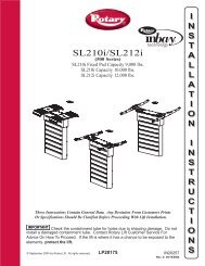
GENERAL SPECIFICATIONS<br />
See Figure 1 E10<br />
A Rise Height (Screw Pads Highest Position) 75 3/4" (1924mm)<br />
B Overall Height 143 7/8" (3655mm)<br />
C Overall Width 131 3/4" (3347mm)<br />
D Drive-Thru Clearance 98 3/8" (2499mm)<br />
E Floor to Overhead Switch 137" (3482mm)<br />
F Short Arm Reach 21 3/4"-39 1/4" (553mm-998mm)<br />
G Long Arm Reach 38 1/4"-55 3/8" (971mm-1407mm)<br />
H Screw Pad Height 4 1/4"-7 3/4" (109mm-199mm)<br />
K Inside of Columns 110 1/4" (2800mm)<br />
Lifting Capacity * 10,000 lbs. (4536 kg)<br />
Ceiling Height Required 144" (3658mm)<br />
Motor 2HP, Single Phase, 60Hz<br />
Voltage 208-230<br />
Speed of Rise ** 50 seconds<br />
Max Load Per Arm 2500 lbs (1134 kg)<br />
* Lift capacity ratings are based on loads equally distributed on all four arms.<br />
** Lifting and lowering speeds may vary depending on the weight of the vehicle.<br />
Fig 1a - General Specifications Fig1b - <strong>Serv</strong>ice Bay Layout<br />
Page 2 Rev. 9/15/09<br />
E10-IOM-A.doc
VERTICAL CLEARANCE<br />
Check the height of the area where the lift is to<br />
be installed. Clearance should be calculated<br />
based on the full raised height of the lift.<br />
Failure by purchaser to<br />
WARNING provide adequate<br />
clearance could result in<br />
unsatisfactory lift performance, property<br />
damage, or personal injury.<br />
FLOORING<br />
Be certain you have the proper concrete floor to<br />
properly handle the loaded lift. Floor should be in<br />
generally good condition with no large cracks,<br />
spalling or deterioration.<br />
Minimum requirements for concrete are 4<br />
inches minimum depth, with steel<br />
reinforcement, 3500 psi, cured for 28 days per<br />
local commercial practice. Floor should be<br />
level within 3/8 inch over the installation area. No<br />
anchors should be installed within 8 inches of any<br />
crack, edge, or expansion joint. If these<br />
conditions cannot be met, a pad may be poured<br />
to accommodate the lift.<br />
Check with local building inspectors and/or<br />
permits office for any special instructions or<br />
approvals required for your installation.<br />
Failure by purchaser to<br />
WARNING provide the recommended<br />
mounting surface could<br />
result in unsatisfactory lift performance,<br />
property damage, or personal injury.<br />
LOCATION<br />
This lift has been evaluated for indoor use only<br />
with an operating ambient temp. range of 5 –<br />
40°C (41– 104°F)<br />
ELECTRICAL REQUIREMENTS<br />
For lift installation and operation for single phase<br />
units, it is necessary to have a dedicated circuit<br />
with a double pole 25 amp circuit breaker or time<br />
delay fuse.<br />
SAFETY NOTICES AND DECALS<br />
For your safety, and the safety of others, read<br />
and understand all of the safety notices and<br />
decals included here.<br />
READ ENTIRE MANUAL BEFORE<br />
ASSEMBLING, INSTALLING,<br />
OPERATING, OR SERVICING THIS<br />
EQUIPMENT.<br />
PROPER MAINTENANCE AND<br />
INSPECTION IS NECESSARY FOR SAFE<br />
OPERATION.<br />
DO NOT OPERATE A DAMAGED LIFT.<br />
Model E10<br />
Installation, Operation and Maintenance<br />
Safety decals similar to those shown here are<br />
found on a properly installed lift. Be sure that all<br />
safety decals have been correctly installed on the<br />
Power Unit reservoir. Verify that all authorized<br />
operators know the location of these decals and<br />
fully understand their meaning. Replace worn,<br />
faded, or damaged decals promptly.<br />
Do not attempt to raise a<br />
WARNING<br />
vehicle on the lift until the<br />
lift has been correctly<br />
installed and adjusted as described in this<br />
manual.<br />
Page 3 Rev. 9/15/09<br />
E10-IOM-A.doc
RECEIVING<br />
The shipment should be thoroughly inspected as<br />
soon as it is received. The signed bill of lading is<br />
acknowledgement by the carrier of receipt in<br />
good condition of shipment covered by our<br />
invoice.<br />
If any of the goods called for on this bill of lading<br />
are shorted or damaged, do not accept them until<br />
the carrier makes a notation on the freight bill of<br />
the shorted or damaged goods. Do this for your<br />
own protection.<br />
NOTIFY Challenger Lifts AT ONCE if any<br />
hidden loss or damage is discovered after<br />
receipt.<br />
IT IS DIFFICULT TO COLLECT FOR LOSS OR<br />
DAMAGE AFTER YOU HAVE GIVEN THE<br />
CARRIER A CLEAR RECEIPT.<br />
File your claim with Challenger Lifts promptly.<br />
Support your claim with copies of the bill of<br />
lading, freight bill, and photographs, if available.<br />
Component Packing List<br />
PART # QTY/ LIFT DESCRIPTION<br />
E10-004R 1<br />
Power Column<br />
Assembly<br />
E10-005R 1<br />
Idler Column<br />
Assembly<br />
JSJ5-03-00CH 1 Overhead Assembly<br />
E10-001 1 Hardware Box<br />
JSJ5-02-02-00CH 1<br />
Power Column<br />
Extension<br />
JSJ5-02-02-00fCH 1<br />
Idler Column<br />
Extension<br />
E10-009 2 Rear Arm Assembly<br />
E10-010 2 Front Arm Assembly<br />
JSJ5-04-00CH 2<br />
Synchronizer Cable<br />
Assembly<br />
E10-012R 1<br />
Hydraulic Hose<br />
Pack<br />
X10-013 1 Power Lock Cover<br />
X10-014 1 Idler Lock Cover<br />
Model E10<br />
Installation, Operation and Maintenance<br />
INSTALLATION<br />
IMPORTANT: Always wear safety glasses while installing lift.<br />
TOOLS (MINIMUM REQUIRED)<br />
a. Tape measure, 16ft<br />
b. Chalk line<br />
c. 4ft level<br />
d. 10” adjustable wrench<br />
e. Metric open end wrenches 10mm, 13mm,<br />
14mm, 15mm, 17mm, 18mm, 19mm and<br />
24mm<br />
f. Metric Allen Wrenches 4mm, 5mm, 6mm,<br />
and 8mm.<br />
g. Needle Nose pliers<br />
h. Snap Ring pliers<br />
i. Hammer drill with 3/4” diameter carbide<br />
tipped bits<br />
j. 2lb hammer<br />
k. Torque wrench: 150 foot pounds minimum<br />
with 1 1/8” socket<br />
l. 12 ft. Step ladder<br />
m. Anti-Seize lubricant (for arm pins and foot<br />
pad screw threads and stop rings)<br />
LAYOUT<br />
1) Layout the service bay according to the<br />
architect’s plans or owners instructions (see<br />
Fig 1b). Failure to install in this<br />
orientation can result in personal and<br />
property damage. Be certain that the<br />
proper conditions exist, see page 3.<br />
2) Assemble column extension to column using<br />
M12 x 30 Hex bolts. Repeat for opposite<br />
column and extension. Install power column<br />
extension on power column, see Fig 6.<br />
3) Using the Overall Width (C) Dimension from<br />
Fig 1b, chalk two parallel lines on the floor<br />
within 1/8” tolerance. Erect both column<br />
assemblies. Align the base plate edges to the<br />
chalk lines.<br />
Page 4 Rev. 9/15/09<br />
E10-IOM-A.doc
ANCHORING<br />
4) The anchor bolts must be installed at least 8”<br />
from any crack, edge, or expansion joint.<br />
5) Use a concrete hammer drill with a 3/4 inch<br />
carbide bit. Tip diameter should conform to<br />
ANSI Standard B94.12-1977 (.775 to .787).<br />
Do not use excessively worn bits or bits<br />
which have been incorrectly sharpened. A<br />
core bit may be necessary if an obstruction is<br />
encountered. Never substitute with shorter<br />
anchor.<br />
6) Recheck “Inside of Columns” dimension,<br />
Fig 1. Drill the anchor holes using the base<br />
plate as a template. Drill through the floor if<br />
possible or to a depth of 5 inches minimum.<br />
7) Vacuum dust from the hole for proper holding<br />
power.<br />
8) Shim both columns to plumb using the shims<br />
provided as shown in Fig 2. DO NOT shim<br />
more than 1/2" at any given point. Use a level<br />
no less than 24” in length to plumb columns.<br />
9) Assemble washer and nut to anchor with nut<br />
just below impact section of bolt. Drive<br />
anchor into hole until nut and washer contact<br />
base.<br />
Fig 2 – Column Shimming<br />
10) Tighten power column anchors and recheck<br />
column for plumb. Re-shim if necessary.<br />
Torque to 150 foot-pounds to set anchors.<br />
OVERHEAD<br />
11) Raise and install Overhead Assembly using<br />
M12 x 30 Hex Bolts.<br />
12) Install Overhead Limit Switch under the<br />
Overhead Assembly on the Power Side.<br />
Route cable around outside of column as<br />
shown in Fig. 6.<br />
13) Check idler column shimming. Use additional<br />
shims (see Fig. 2) to remove any gaps that<br />
may have been created while installing<br />
overhead beam. Tighten anchor bolts and recheck<br />
column for plumb. Torque to 150 footpounds.<br />
Model E10<br />
Installation, Operation and Maintenance<br />
SYNCHRONIZER CABLES<br />
14) Manually raise each carriage into the second<br />
lock position.<br />
15) At the upper beam sheave locations<br />
disassemble and reassemble the cable<br />
trapping rod to install the cable onto the<br />
sheave, See Fig 3. To install the cable<br />
bottom sheave will need to be removed then<br />
reassembled.<br />
Fig 3-Cable Trapping<br />
16) Attach one end of synchronizing cable to<br />
carriage. See Fig 4 for proper attachment.<br />
17) Route cable up and over sheave in<br />
overhead. Follow across to other sheave on<br />
opposite column. Route down through<br />
carriage to sheave in bottom of column.<br />
Route under sheave and up to cable<br />
attachment. Use Fig 4 for proper attachment.<br />
18) Repeat for opposite side.<br />
Fig 4 – Synchronizing Cables<br />
POWER UNIT & HYDRAULIC LINES<br />
Fig 5 – Power Unit Mounting<br />
Page 5 Rev. 9/15/09<br />
E10-IOM-A.doc
19) Mount Power Unit to power column as shown<br />
in Fig 5. The mounting hardware, (4) M8 hex<br />
nuts, are pre-installed on power unit<br />
mounting bracket.<br />
20) Attach Hydraulic elbow fitting threading the<br />
O-Ring end into the power unit.<br />
21) IMPORTANT – To insure proper hose<br />
fitting seal without damage to the fitting<br />
follow this procedure for each hose<br />
connection: Screw flared fitting on finger<br />
tight. Rotate flared fitting 1 ½ flats or 90<br />
degrees. Back the flared fitting off one full<br />
turn and repeat.<br />
22) Thread power unit hose (short) to elbow in<br />
power on power unit.<br />
23) Beginning on the idler side start with the Idler<br />
Column Hose (long) up the backside of the<br />
column through the two capture rings and<br />
guide at the top of the extension. Continue<br />
across the overhead through each of the<br />
guides as shown and down the backside of<br />
the power column. See Fig 6.<br />
Hydraulic Hose<br />
Synchronizing<br />
Cables<br />
Model E10<br />
Installation, Operation and Maintenance<br />
Lock Release<br />
Cable<br />
Overhead<br />
Shutoff Cord<br />
Fig 6 – Hose Routing (Power Side)<br />
24) Route the remaining Power column hose<br />
beginning at the elbow fitting at the base up<br />
the backside of the column. Join the three<br />
hoses with the supplied union tee.<br />
25) BE CERTAIN ALL FITTINGS AND CONNECTIONS<br />
ARE TIGHT. IT IS THE INSTALLERS<br />
RESPONSIBILITY TO INSURE SYSTEM IS LEAK-<br />
FREE. Fill the Power Unit with three gallons of<br />
clean 10wt anti-foam anti-rust hydraulic oil or<br />
Dexron III ATF. DO NOT USE OILS WITH<br />
DETERGENTS.<br />
LOCK RELEASE<br />
26) Install Lock Release Stud and Knob to the<br />
Powre Column Lock using one M10 Nut.<br />
27) Attach Mechanical Lock Release Cable<br />
Assembly to each lock pawl. See Fig 7.<br />
Fig 7 – Lock Assembly<br />
THE LOCK RELEASE CABLE ADJUSTMENT IS NOT<br />
COMPLETE UNTIL THE LIFT HAS BEEN LOWERED AND<br />
“FINAL ADJUSTMENTS” HAVE BEEN MADE.<br />
ARM INSTALLATION<br />
28) Lubricate the arm pin or carriage arm pin<br />
hole with “anti-seize” and install the arms.<br />
Insure that the arm restraint gears engage<br />
and disengage properly. Arm restraints<br />
should disengage when lift is fully lowered. If<br />
any binding occurs, insure that the large gear<br />
mounted to the arm has been factory<br />
installed tight against the arm pin.<br />
29) Extend the foot pad to both extents and apply<br />
anti-seize to the three retaining rings and<br />
where the double screw makes contact with<br />
the base of the foot pad.<br />
ELECTRICAL<br />
30) Refer to Fig 9 Wiring Diagram for all steps<br />
under this heading.<br />
Single Phase<br />
31) Connect the Overhead Limit Switch Cord to<br />
Power Unit as shown.<br />
32) Connect Power Unit to suitable electrical<br />
source as shown.<br />
Three Phase<br />
33) Power unit is factory wired for 240 volt.<br />
Refer to wiring diagram or motor plate for<br />
optional voltages.<br />
34) Connect Contactor Enclosure to column.<br />
Mounting hardware should be centered on<br />
the column side to side to avoid the path of<br />
the slide blocks.<br />
35) Connect Overhead Limit Switch Cord to<br />
Contactor as shown.<br />
36) Connect Contactor to Power unit as shown.<br />
Connect Contactor to suitable electrical<br />
source as shown.<br />
IMPORTANT: AFTER WIRING HAS BEEN<br />
COMPLETED, TEST OPERATION OF POWER UNIT &<br />
OVERHEAD LIMIT SWITCH. WHILE RAISING LIFT,<br />
OPERATE OVERHEAD SHUTOFF BAR. POWER UNIT<br />
MOTOR SHOULD STOP WHEN SHUTOFF BAR IS<br />
RAISED.<br />
Page 6 Rev. 9/15/09<br />
E10-IOM-A.doc
COLUMN DECAL PLACEMENT<br />
37) Center decal on idler column, opposite of the<br />
power unit.<br />
38) Apply the decal 48” from the top of the base<br />
plate, Fig 8.<br />
FINAL ADJUSTMENTS<br />
Fig 8 – Decal Placement<br />
HYDRAULICS<br />
39) Lower the lift to the floor and raise the lift<br />
approximately one foot.<br />
40) Start with Idler side first. Slowly and carefully<br />
loosen the bleed plug on top side of the<br />
cylinder just enough to allow the entrapped<br />
air to escape. Repeat for power side.<br />
41) Raise lift 6 inches. Repeat step 32 until no air<br />
comes out of cylinder.<br />
42) Pressure test hydraulic system. Energize<br />
power unit, raise lift to full rise and continue<br />
to run motor for additional 10 seconds.<br />
(NOTE: pressure relief will make a high pitch<br />
squeal sound for these 10 seconds.) Check<br />
hydraulic system for leaks.<br />
43) Energize power unit again for 10 seconds.<br />
With a clean rag, wipe down both cylinder<br />
rods. (The cylinders are shipped with a small<br />
amount of clear anti-corosive lubricant that<br />
will be forced out through the wiper when the<br />
lift reaches full rise.) If lubricant is not<br />
wiped clean from the cylinder rod, the<br />
cylinder will apear to be leaking.<br />
SYNCHRONIZING CABLES<br />
44) Raise lift and insure carriages lower into<br />
same lock position.<br />
45) Adjust synchronizing cables so the tension is<br />
equal in both cables and carriages are firmly<br />
sitting on locks.<br />
Model E10<br />
Installation, Operation and Maintenance<br />
46) Cycle lift to insure that latches operate<br />
simultaneously.<br />
LOCK RELEASE CABLE<br />
47) Raise lift to a lock position but don’t set into<br />
the lock. Pull and release Power Column<br />
lock release handle while watching Idler<br />
Column lock. Adjust Cable tension by<br />
removing slack and retightening cable clamp<br />
at the power side. IMPORTANT: IF IDLER<br />
SIDE LOCK PAWL DOES NOT FULLY DISENGAGE,<br />
DAMAGE MAY RESULT TO IDLER SIDE CARRIAGE<br />
AND OR CABLE SYNCHRONIZING SYSTEM.<br />
48) Tighten and trim wire ties.<br />
49) Remove lock release knob and install both<br />
covers. Replace lock release knob.<br />
OWNER/OPERATOR CHECKLIST<br />
50) Demonstrate the operation of the lift to the<br />
owner/operator and review correct and safe<br />
lifting procedures using the Lifting It Right<br />
booklet as a guide.<br />
51) Complete the Installation Checklist/Warranty<br />
Validation questionnaire with the owner.<br />
Review the terms of the warranty registration<br />
card, and return the card and a copy of the<br />
questionnaires to:<br />
Challenger Lifts, Inc.<br />
200 Cabel Street<br />
Louisville, KY. 40206<br />
Page 7 Rev. 9/15/09<br />
E10-IOM-A.doc
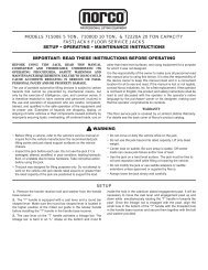
FOR SINGLE PHASE<br />
FOR THREE PHASE<br />
Model E10<br />
Installation, Operation and Maintenance<br />
Wiring Diagram<br />
(Normally Open)<br />
A1<br />
L1<br />
L2<br />
L3<br />
T1<br />
T2<br />
T3<br />
A2<br />
FIELD<br />
CONECTIONS<br />
1<br />
6<br />
2<br />
4<br />
6<br />
2<br />
4<br />
6<br />
5<br />
4<br />
M<br />
Fig 9 – Electrical Wiring Diagram<br />
Page 8 Rev. 9/15/09<br />
E10-IOM-A.doc<br />
1<br />
3<br />
5<br />
1<br />
3<br />
5<br />
FACTORY WIRED FOR<br />
208−240V<br />
T1<br />
T7<br />
T2<br />
T8<br />
T3<br />
T9<br />
RECONNECTIONS FOR<br />
440−480V<br />
T1<br />
T2<br />
T3<br />
M<br />
M<br />
T4<br />
T5<br />
T6<br />
T4<br />
T7<br />
T5<br />
T8<br />
T6<br />
T9
OPERATION PROCEDURE<br />
SAFETY NOTICES AND DECALS<br />
This product is furnished with graphic safety<br />
warning labels, which are reproduced on<br />
page 3 of these instructions. Do not remove<br />
or deface these warning labels, or allow them<br />
to be removed or defaced. For your safety,<br />
and the safety of others, read and understand<br />
all of the safety notices and decals included.<br />
OWNER/EMPLOYER RESPONSIBILITIES<br />
This lift has been designed and constructed according<br />
to ANSI/ALI ALCTV-2006 standard. The standard<br />
applies to lift manufactures, as well as to owners and<br />
employers. The owner/employer’s responsibilities as<br />
prescribed by ANSI/ALI ALOIM-2000, are summarized<br />
below. For exact wording refer to the actual standard<br />
provided with this manual in the literature pack.<br />
The Owner/Employer shall insure that lift<br />
operators are qualified and that they are trained<br />
in the safe use and operation of the lift using the<br />
manufacturer’s operating instructions; ALI/SM<br />
93 -1, ALI Lifting it Right safety manual; ALI/ST-<br />
90 ALI Safety Tips card; ANSI/ALI ALOIM-2000,<br />
American National Standard for Automotive Lifts-<br />
Safety Requirements for Operation, Inspection<br />
and Maintenance; ALI/WL Series, ALI Uniform<br />
Warning Label Decals/Placards; and in case of<br />
frame engaging lifts, ALI/LP-GUIDE, Vehicle<br />
Lifting Points/Quick Reference Guide for Frame<br />
Engaging Lifts.<br />
The Owner/Employer shall establish<br />
procedures to periodically inspect the lift in<br />
accordance with the lift manufacturer’s<br />
instructions or ANSI/ALI ALOIM-2000, American<br />
National Standard for Automotive Lifts-Safety<br />
Requirements for Operation, Inspection and<br />
Maintenance; and the employer shall insure that<br />
the lift inspectors are qualified and that they are<br />
adequately trained in the inspection of the lift.<br />
The Owner/Employer shall establish<br />
procedures to periodically maintain the lift in<br />
accordance with the lift manufacturer’s<br />
instructions or ANSI/ALIOIM-2000, American<br />
National Standard for Automotive Lifts-Safety<br />
Requirements for Operation, Inspection and<br />
Maintenance; and the employer shall insure that<br />
the lift maintenance personnel are qualified and<br />
that they are adequately trained in the<br />
maintenance of the lift.<br />
The Owner/Employer shall maintain the<br />
periodic inspection and maintenance records<br />
recommended by the manufacturer or ANSI/ALI<br />
ALOIM-2000, American National Standard for<br />
Automotive Lifts-Safety Requirements for<br />
Operation, Inspection and Maintenance.<br />
Model E10<br />
Installation, Operation and Maintenance<br />
The Owner/Employer shall display the lift<br />
manufacturer’s operating instructions; ALI/SM<br />
93 -1, ALI Lifting it Right safety manual; ALI/ST-<br />
90 ALI Safety Tips card; ANSI/ALI ALOIM-2000,<br />
American National Standard for Automotive Lifts-<br />
Safety Requirements for Operation, Inspection<br />
and Maintenance; and in the case of frame<br />
engaging lift, ALI/LP-GUIDE, Vehicle Lifting<br />
Points/Quick Reference Guide for Frame<br />
Engaging Lifts; in a conspicuous location in the<br />
lift area convenient to the operator.<br />
IMPORTANT SAFETY INSTRUCTIONS<br />
When using your garage equipment, basic safety<br />
precautions should always be followed, including<br />
the following:<br />
1. Read all instructions.<br />
2. Care must be taken as burns can occur from<br />
touching hot parts.<br />
3. To reduce the risk of fire, do not operate<br />
equipment in the vicinity of open containers<br />
of flammable liquids (gasoline).<br />
4. Keep hair, loose clothing, fingers, and all<br />
parts of body away from moving parts.<br />
5. Use only as described in this manual. Use<br />
only manufacturer’s recommended<br />
attachments.<br />
6. ALWAYS WEAR SAFETY GLASSES.<br />
Everyday eyeglasses only have impact<br />
resistant lenses, they are not safety glasses.<br />
SAVE THESE INSTRUCTIONS<br />
Page 9 Rev. 9/15/09<br />
E10-IOM-A.doc
LIFTING A VEHICLE<br />
1) Insure that the lifting arms are parked, out to<br />
full drive thru position.<br />
2) Center the vehicle between the columns in the<br />
service bay and position the vehicle’s center<br />
of gravity midpoint between the columns.<br />
NOTE: the center of gravity is based on the<br />
weight distribution and is not the same as the<br />
center point of the vehicle.<br />
DO NOT EXCEED 2500 POUNDS PER ARM.<br />
DO NOT ATTEMPT TO LIFT THE VEHICLE WITH ONLY<br />
TWO ARMS, AS THIS WILL VOID THE WARRANTY<br />
INSURE THAT THE HIGHEST POINT ON THE VEHICLE<br />
WILL CONTACT THE OVERHEAD LIMIT SWITCH BAR.<br />
DO NOT PLACE THE VEHICLE IN THE SERVICE BAY<br />
BACKWARDS.<br />
REFER TO THE VEHICLE MANUFACTURERS SERVICE<br />
MANUAL, TECHNICAL BULLETINS, “VEHICLE LIFTING<br />
POINTS GUIDE” (ALI/LP-GUIDE) OR OTHER<br />
PUBLICATIONS TO LOCATE THE RECOMMENDED<br />
LIFTING POINTS.<br />
3) Position the arms and adapters so all four<br />
pads contact the vehicle simultaneously.<br />
The vehicle should remain level during lifting.<br />
4) Raise the lift until all four wheels are off the<br />
ground. Test the stability of the vehicle by<br />
attempting to rock the vehicle. Check adapters<br />
for secure contact with vehicle lift points. If the<br />
vehicle seems unstable, lower the lift and<br />
readjust the arms. If the vehicle is stable,<br />
raise the vehicle to a height a few inches<br />
above the desired working height.<br />
5) Lower the vehicle until the safety latches on<br />
both columns engage. The vehicle should<br />
remain level when both latches are engaged.<br />
If one side engages and the other continues to<br />
descend, stop lowering the vehicle, raise it<br />
several inches, and try again to engage both<br />
latches.<br />
Always lower lift into locks before entering<br />
the area beneath the vehicle.<br />
Always use safety stands when removing or<br />
installing heavy components.<br />
LOWERING A VEHICLE<br />
1) Insure that the area under the vehicle is clear<br />
of personnel and tools.<br />
2) Raise the vehicle until both latches are free.<br />
3) Disengage the latches by pulling down and<br />
holding the lock release lever.<br />
4) Lower the vehicle by depressing the lowering<br />
valve handle.<br />
5) Continue to lower the vehicle until the<br />
carriages stop against the base plate. Retract<br />
the extension arms, and park them.<br />
Model E10<br />
Installation, Operation and Maintenance<br />
MAINTENANCE<br />
To avoid personal injury, permit only qualified<br />
personnel to perform maintenance on this<br />
equipment. Maintenance personnel should follow<br />
lockout/tagout instructions per ANSI Z244.1.<br />
The following maintenance points are suggested<br />
as the basis of a routine maintenance program.<br />
The actual maintenance program should be<br />
tailored to the installation. See ANSI/ALI ALOIM<br />
booklet for periodic inspection checklist and<br />
maintenance log sheet.<br />
• If lift stops short of full rise or chatters, check<br />
fluid level and bleed both cylinders per<br />
Installation Instructions.<br />
• Replace all Safety, Warning or Caution Labels<br />
if missing or damaged (See Installation<br />
instructions page 3.)<br />
Daily<br />
• Keep lift components clean.<br />
• Check for loose or broken parts.<br />
• Check hydraulic system for fluid leaks.<br />
• Check adapters for damage or excessive wear.<br />
Replace as required with genuine Challenger<br />
Lifts parts.<br />
• Check lock release activation. When properly<br />
adjusted, the idler column lock should rest<br />
firmly against the back of the column when<br />
engaged and pull clear of the column back<br />
when disengaged.<br />
Weekly<br />
• Check synchronizer cables and sheaves for<br />
wear. Replace as required with genuine<br />
Challenger Lifts parts.<br />
• Check lock release cable adjustment per<br />
Installation Instructions step 39.<br />
IMPORTANT: IF IDLER SIDE LOCK PAWL DOES<br />
NOT FULLY DISENGAGE, DAMAGE MAY RESULT<br />
TO IDLER SIDE CARRIAGE AND OR CABLE<br />
SYNCHRONIZING SYSTEM.<br />
• Check synchronizer cable tension per<br />
Installation Instructions. Adjust if necessary.<br />
Monthly<br />
• Torque concrete anchor bolts to 80 ft-lbs.<br />
• Check overhead shutoff switch. While raising<br />
lift, operate overhead shutoff bar. Power Unit<br />
motor should stop when bar is raised.<br />
• Lubricate carriage slide tracks with heavy<br />
viscous grease. (Grease all (4) corners of both<br />
columns.)<br />
• Visually inspect concrete floor for cracks and/or<br />
spalls within 12” of base plate<br />
If any problems are encountered, contact<br />
your local service representative.<br />
Page 10 Rev. 9/15/09<br />
E10-IOM-A.doc
Model E10<br />
Installation, Operation and Maintenance<br />
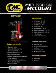
Parts Breakdown<br />
Page 11 Rev. 9/15/09<br />
E10-IOM-A.doc
Model E10<br />
Installation, Operation and Maintenance<br />
Page 12 Rev. 9/15/09<br />
E10-IOM-A.doc
Model E10<br />
Installation, Operation and Maintenance<br />
Item # Part # Qty. Description Item # Part # Qty. Description<br />
1 JSJ5-02-01-00CH 1 Power Column Weld 47 X10-058 2 Axle<br />
JSJ5-02-01-00fCH 1 Idler Column Weld 48 X10-059 2 Middle Spacer Sleeve<br />
2 JSJ5-02-02-00CH 1 Power Extension Weld 49 X10-060 2 Bolt M8 x 25<br />
JSJ5-02-02-00fCH 1 Idler Extension Weld 50 36027 1 Limit Switch<br />
3 X10-013 1 Power Lock Cover 51 X10-061 1 Shutoff Bar Cushion<br />
X10-014 1 Idler Lock Cover 52 JSJ5-03-02CH 1 Shutoff Bar<br />
4 X10-065 8 Screw M5 x10 53 X10-063 1 Bolt M8<br />
5 X10-017 1 Lock Release Knob 54 JSJ4-02-11-00 1R/1L Pulley Bracket<br />
6 X10-018 1 Lock Release Stud 55 B2250 4 Foot Pad Assembly<br />
7 X10-019 1 Nut M10 55A B2208 4 Rubber Insert<br />
8 X10-020 4 “C” Ring 20 55B B2205 4 Foot Pad Weld<br />
9 X10-021 2 Lock Release Wire Pin 55C B17256 4 2x30 Retaining Ring<br />
10 X10-022 2 Lock Release Spring 1 55D B17254 4 Threaded Sleeve<br />
11 X10-023 2 Lock Release Spring 2 55E B17257 8 3x45 Retaining Ring<br />
12 X10-024 2 Lock Release Shaft 55F B17276-1 4 Threaded Insert<br />
13 X10-025 2 Lock Release Cam 57 B2211 4 Roll Pin, ø6x30<br />
14 X10-026 2 Bolt M6 61 JSJ5B090200CH 2 Rear Male Arm<br />
15 X10-027 2 Spring Pin 6 x 35 62 JSJ5B090100B 2 Rear Female Arm<br />
16 X10-028 2 Lock Pawl 63 X10-073 6 Washer 10mm<br />
17 X10-029 2 Washer 64 X10-074 18 Spring Washer 10mm<br />
18 X10-030 4 Pulley Axle 65 X10-075 6 Screw M10<br />
19 X10-031 4 Pulley 66 X10-076 4 Arm Pin<br />
20 X10-032 12 Washer 6mm 67 X10-077 12 Screw M10 x 25<br />
21 X10-033 12 Spring Washer 6mm 68 X10-078 4 Inner Gear<br />
22 X10-034 13 Nut M6 69 X10-079 4 Arm Restraint Pin<br />
23 X10-035 1 Bolt (Cable Clamp) 70 X10-080 4 Spring Pin 4 x 24<br />
24 X10-036 1 Sleeve 71 X10-081 4 Spring Pin 4 x 30<br />
25 X10-037 28 Bolt M12 x 30 72 X10-082 4 Arm Restraint Spring<br />
26 X10-038 28 Washer 12mm 73 X10-083 4 Outer Gear<br />
27 X10-039 28 Spring Washer 12mm 74 X10-084 16 Slide Block<br />
28 X10-040 28 Nut M12 75 JSJ5-08-00CH 2 Carriage<br />
29 X10-041 1 Idler Column Hose 76 JSJ4-05 2 Door Guard<br />
30 X10-042 1 Union Tee 77 X10-087 4 Washer 8mm<br />
31 JSJ5-17CH 1 Power Unit Hose 78 X10-088 4 Bolt M8 x 30<br />
32 X10-044 1 O-Ring Elbow 79 JSJ5B100300CH 2 Front Male Arm<br />
33 31368-21 1 Power Unit 80 JSJ5B100200 2 Front Intermediate Arm<br />
34 JSJ4-16 1 Power Column Hose 81 JSJ5B100100 2 Front Female Arm<br />
35 X10-046 2 Long Elbow 82 X10-092 2 Bolt M12 x 45<br />
36 JSJ5-07-00CH 2 Cylinder 83 JSJ5-03-01-00CH 1 Overhead Weld<br />
37 X10-048 4 Nut M8 84 JSJ5-04-00CH 2 Synchronizing Cable<br />
38 X10-049 10 Bolt M5 x 8 85 X10-095 8 Nut M16<br />
39 X10-050 5 Plate-Shutoff Cord Clamp 86 X10-096 2 Lock Nut M10<br />
40 X10-051 8 Bolt M6 x 20 87 JSJ5-06CH 1 Lock Release Cable<br />
41 X10-052 2 Hose Guide 88 X10-099 4 Washer 20mm<br />
42 X10-053 2 Hose Guide Nut 89 B31061 4 M6 Lock Nut<br />
43 X10-054 6 Hair Pin Cotter 90 JSJ5-03-07ch 2 Cable Trapping Rod<br />
44 X10-055 4 Washer 91 JSJ5-02-03-00Q 1 Hose Guide, Power Column<br />
45 X10-056 4 Spacer Sleeve 92 JSJ5-02-03-00fQ 1 Hose Guide, Idler Column<br />
46 X10-057 6 Synch. Sheave<br />
IMPORTANT Replace all worn or broken parts with genuine Challenger Lifts, Inc. parts.<br />
Contact your local Challenger Lifts parts distributor for pricing and availability. Call Challenger<br />
Lifts, Inc. at (502) 625-0700 for the distributor in your area.<br />
Page 13 Rev. 9/15/09<br />
E10-IOM-A.doc