Fireye® Flame Safeguard Controls - Fireye Inc.
Fireye® Flame Safeguard Controls - Fireye Inc.
Fireye® Flame Safeguard Controls - Fireye Inc.

You also want an ePaper? Increase the reach of your titles
YUMPU automatically turns print PDFs into web optimized ePapers that Google loves.
<strong>Fireye</strong> ® <strong>Flame</strong> <strong>Safeguard</strong> <strong>Controls</strong><br />
®<br />
SYSTEM COMPONENTS CATALOG
FLAME SAFEGUARD CONTROLS<br />
Systems Components Products<br />
For over 70 years, <strong>Fireye</strong> has manufactured quality flame safeguard and combustion<br />
controls for the industrial market. We are proud of our global reputation and<br />
worldwide market position. Dedicated to a constant process of innovation and<br />
service, we consistently provide safe and reliable products to our customers.
IMPORTANT NOTICE<br />
Periodically, <strong>Fireye</strong> receives inquiries from the field concerning the use of rebuilt controls.<br />
In years past, <strong>Fireye</strong> and other manufacturers of flame safety devices did rebuild<br />
controls.<br />
These rebuilt controls were certified by a “nationally recognized testing agency” (UL)<br />
and subject to different standards than new equipment. Essentially, all components were<br />
replaced with the exact components that were used in a new control. Only the housings<br />
and lenses (if applicable) were reused. <strong>Fireye</strong> no longer rebuilds controls (as of 1989), nor<br />
have we authorized any other company to rebuild for us.<br />
Currently, there are several other companies selling “rebuilt” or “reconditioned controls.<br />
None of these companies have an approval from any nationally recognized testing<br />
agency. What this means is the following:<br />
1. <strong>Fireye</strong> assumes no liability for any incident resulting from the use of a rebuilt<br />
control.<br />
2. Your insurance coverage should be reviewed if you use rebuilt controls.<br />
3. The use of safety controls rebuilt by any party other than the original manufacturer<br />
is in violation of ASME, CSD-1 standard.<br />
4. Use of rebuilt controls is in violation of National Fire Protection Agency Association.<br />
For over seventy years, <strong>Fireye</strong> has been a leader in promoting flame safety. We are<br />
very committed to adhering to standards established by testing agencies, fire codes and<br />
insurance requirements as well as developing new scanner technology.
TABLE OF CONTENTS<br />
Part Number Index 1<br />
Tables of Scanners 4<br />
Series 95IR/ 95UV/ 95DS Scanners 8<br />
Series 85UVF / IRF 10<br />
Series 45FS1/45UVFS1 Scanners 11<br />
Series 45RM/45UV Scanners 13<br />
Fiber Optic Assemblies 17<br />
Series 25SU5/25SU3 Amplifiers and <strong>Controls</strong> 23<br />
Series C9000/R9000 Scanners and <strong>Controls</strong> 34<br />
Series C9000 Fiber Optic Assemblies 36<br />
SureFire High Energy Igniters 39<br />
SureFire 20 Gas Igniters 42<br />
Sales Offices 47<br />
Terms and Conditions 48
©<strong>Fireye</strong>, <strong>Inc</strong>. 2009<br />
The names FIREYE, MicroM, SIGNATURE SCANNER, and FLAME-MONITOR, and the <strong>Fireye</strong> logo are registered<br />
trademarks of <strong>Fireye</strong>, <strong>Inc</strong>.<br />
Products in this catalog are not necessarily shown to scale.<br />
For additional information visit our web site www.fireye.com<br />
NOTICE: When <strong>Fireye</strong> products are combined with equipment manufactured by others and/or integrated into<br />
systems designed or manufactured by others, the <strong>Fireye</strong> warranty, as stated in its General Terms and Conditions of<br />
Sale, pertain only to the <strong>Fireye</strong> products and not to any other equipment or to the combined system or its overall<br />
parts.
PART NUMBER INDEX<br />
PART NUMBER PAGE<br />
C9501N5023 34<br />
C9501N5034 34<br />
C9502N5012 34<br />
C9502N5023 34<br />
C9502Q6001 34<br />
C9502Q6012 34<br />
C9503M-001 36<br />
C9504M-001 36<br />
C9506M1085 34<br />
C9506M1096 34<br />
C9507N4001 34<br />
C9507N4012 34<br />
C9508M2000 34<br />
C9508M2011 34<br />
C9508M2022 34<br />
C9701A1012 34<br />
C9701A1023 34<br />
C9707A1012 34<br />
C9707A1023 34<br />
DE601-006 35<br />
DE601-006B 35<br />
DE601-08 35<br />
DE601-16 37<br />
DE601-18 37<br />
DE601-20A1 37<br />
DE601-20B1 37<br />
DE601-20C1 37<br />
DE601-20D1 37<br />
DE601-104D 35<br />
DE601-104F 35<br />
DE601-104G 35<br />
DE601-106 35<br />
DE601-106C 35<br />
DE601-108A 35<br />
PART NUMBER PAGE<br />
DE601-108AC 35<br />
DE601-110 37<br />
DE601-111 37<br />
DE601-112B 37<br />
DE601-112C 37<br />
DE601-112D 37<br />
DE601-112E 37<br />
DE601-113 35<br />
DE601-113C 35<br />
DE601-114 35<br />
DE701-007A 35<br />
DE701-007C 35<br />
DE701-107A 35<br />
DE701-107C 35<br />
DE4360-XXX 35<br />
DE4599-XXX 35<br />
DE4606-001 35<br />
DE4643-001 38<br />
DE5213-001 35<br />
GH20-04 43<br />
GH20-06 43<br />
GH20-08 43<br />
MT1R-022 41<br />
MT1R-168 41<br />
MT1-006 40<br />
MT1-016 40<br />
MT1-026 40<br />
MT1-036 40<br />
MT1-046 40<br />
MT1-056 40<br />
MT1-066 40<br />
MT1-076 40<br />
MT1-086 40<br />
MT1-096 40<br />
PART NUMBER PAGE<br />
MT1-106 40<br />
MT1-116 40<br />
MT1-126 40<br />
MT1-136 40<br />
MT1-146 40<br />
MT1-156 40<br />
MT1-166 40<br />
MT20-004 43<br />
MT20-012 43<br />
MT20-022 43<br />
MT20-032 43<br />
MT20-042 43<br />
MT20-052 43<br />
MT20-062 43<br />
MT20-072 43<br />
MT20-082 43<br />
MT20-092 43<br />
MT20-102 43<br />
MT20-112 43<br />
MT20-122 43<br />
MT20-132 43<br />
MT20-142 43<br />
MT20-152 43<br />
MT20-162 43<br />
Q2625A1303 35<br />
Q2625A1314 35<br />
Q9050A1000 37<br />
Q9105 38<br />
Q9801C1124 38<br />
Q9801C1126 38<br />
R9005P5001 38<br />
R9105P5002 38<br />
R9006M3000 38<br />
R9006M3011 38<br />
FIREYE ® System Components 1
PART NUMBER PAGE<br />
R9008M4001 38<br />
R9107A1001 38<br />
R9108M4001 38<br />
SFR-014 39<br />
SFR-180 39<br />
SF1-1 39<br />
SF1-2 39<br />
SF1-3 39<br />
SF1-4 39<br />
SF1-CA1-06 40<br />
SF1-CA1-09 40<br />
SF1-CA1-12 40<br />
SF1-CA1-15 40<br />
SF1-RET-1 40<br />
SF1-RET-2 40<br />
SF1-RET-3 40<br />
SF1-RET-4 40<br />
SF1-RET-5 40<br />
SF1-RET-6 40<br />
000710-023 35<br />
003181-001 38<br />
003263-001 36<br />
003263-002 36<br />
003263-003 36<br />
003263-004 36<br />
003265-001 36<br />
003265-002 36<br />
003265-003 36<br />
003265-004 36<br />
4-290-2 21, 44<br />
5-563 41<br />
7-1738 41<br />
8-705 41<br />
8-706 41<br />
9-438 43<br />
10-211 43<br />
2 FIREYE ® System Components<br />
PART NUMBER PAGE<br />
16-103 21<br />
19MPS-2000 26, 30<br />
19UVPS-2120 26, 29<br />
19UVPS-2220 26, 29<br />
192SU3-2120 26<br />
192SU3-2220 26<br />
25SU3-2100 7, 26<br />
25SU3-4169T 7<br />
25SU3-4170 7<br />
25SU3-4171 7<br />
25SU3-4172 7<br />
25SU3-5166 7, 24<br />
25SU3-5168 7, 24<br />
25SU3-5172 7<br />
25SU3-5173 7<br />
25SU5-5011 7, 24<br />
25SU5-5012 7, 23, 24<br />
25SU5-5013 7, 23, 24<br />
34-181 21<br />
35-127-1 21<br />
35-127-3 21<br />
35-200 21, 44<br />
35-201 21, 44<br />
35-202 21, 44<br />
35-240 21, 44<br />
35-309 43<br />
38-54 32, 44<br />
38-55 32, 44<br />
38-56 32, 44<br />
38-62 44<br />
38-88 32, 44<br />
38-96 32<br />
38-97 32<br />
45FS1-1000 6, 12<br />
45FS1-1000CEX 16, 12<br />
45FS1-1000EX 7, 12<br />
PART NUMBER PAGE<br />
45FS1-1001 6, 12<br />
45RM1-1001 6, 15<br />
45RM1-1001EX 7, 15<br />
45RM1-1003 6, 15<br />
45RM2-1000 6, 14<br />
45RM2-1000EX 7, 14<br />
45RM2-1001 6, 14<br />
45RM4-1000 6, 13<br />
45RM4-1000CEX 7, 13<br />
45RM4-1000EX 7, 13<br />
45RM4-1001 6, 13<br />
45UV5-1000 6, 16<br />
45UV5-1000CEX 7, 16<br />
45UV5-1000EX 7, 16<br />
45UV5-1010 6, 16<br />
45UV5-1101 6, 16<br />
45UV5-1101CEX 7, 16<br />
45UV5-1101EX 7, 16<br />
45UVFS1-1000 6, 12<br />
45UVFS1-1001 6, 12<br />
45UVFS1-1000CEX 7, 12<br />
45UVFS1-1000EX 7, 12<br />
46-4 21<br />
46-38 21<br />
46-87 21<br />
46-179 21<br />
48-1805 24<br />
53-121 21<br />
59-470 22, 44<br />
59-470-XXX 22<br />
59-471 22, 44<br />
59-471-XXX 22<br />
59-495 43<br />
59-497 9<br />
59-497-XXX 9<br />
60-1199 21
PART NUMBER PAGE<br />
60-1622 21, 45<br />
60-1664-3 21<br />
60-1664-4 21<br />
60-2203-2 24<br />
60-2204-2 24<br />
60-2205 24<br />
60-2206-1 24<br />
60-2206-2 24<br />
60-2207-1 24<br />
60-2207-2 24<br />
60-2207-3 24<br />
60-2223 24<br />
60-2301 24<br />
60-2366 21, 45<br />
60-2367 24<br />
60-2470-1 26, 31<br />
60-2470-2 26, 31<br />
60-2471-1 26<br />
60-2471-3 26<br />
60-2478 26<br />
60-2481 26, 30<br />
60-2482 26, 30<br />
60-2490-10 27<br />
60-2530-1 26<br />
60-2530-2 26<br />
60-2692 9<br />
60-2693 9<br />
60-6671-X 22<br />
61-2275-2 21, 45<br />
61-2275-3 21<br />
61-2275-4 21<br />
61-2841-1 21, 45<br />
61-2841-2 21, 45<br />
61-2913-1 21<br />
61-2914-1 21, 45<br />
61-4468 21<br />
61-4892-2 15<br />
PART NUMBER PAGE<br />
61-5234 14<br />
61-6521 13<br />
61-6625 12<br />
61-6694-1 12<br />
61-6944-XXX 22<br />
61-7203 21, 45<br />
70-426 41<br />
70-427 41<br />
82-95 21<br />
85IRF1-1QD 5, 10<br />
85UVF1-1QD 5, 10<br />
85IRF4-1QDWR 5, 10<br />
85UVF4-1QDWR 5, 10<br />
85IRF1-2QD 19<br />
85UVF1-2QD 19<br />
85IRF4-2QDWR 19<br />
85UVF4-2QDWR 19<br />
92-48 21<br />
95DSS2-1 9<br />
95DSS2E-1 9<br />
95IRS2-1 9<br />
95IRS2E-1 9<br />
95UVS2-1 9<br />
95UVS2E-1 9<br />
101-78 21, 45<br />
129-127-6 21, 45<br />
129-164(R) 9<br />
129-174 41<br />
145-18 43<br />
145-19 43<br />
148-21 43<br />
192SU3-2120 26<br />
192SU3-2220 26<br />
101363-002 38<br />
101806-001 37<br />
101806-002 37<br />
101806-003 37<br />
PART NUMBER PAGE<br />
101806-004 37<br />
102531-001 37<br />
102531-002 37<br />
102531-003 37<br />
102531-004 37<br />
500287-001 35<br />
FIREYE ® System Components 3
Table 1: InSight Integrated Scanners 95IR, 95UV, 95DS (24 VDC)<br />
PART<br />
NUMBER<br />
SENSOR FIBER<br />
OPTIC<br />
MOUNT<br />
4 FIREYE ® System Components<br />
12-PIN<br />
CONNECTOR<br />
10 FT (3M)<br />
CABLE &<br />
GLAND<br />
MAXIMUM<br />
CONTACT<br />
RATING<br />
HOUSING<br />
RATING<br />
(see note)<br />
AGENCY APPROVALS<br />
Note: The housing into which the Model CEX InSight electronics are installed has been approved<br />
by CENELEC and ATEX for use in EExd IIC T6 hazardous areas.<br />
Note: Class I Division 2 Hazardous Area requirements for InSight scanners with electrical connectors<br />
(non-CG models):<br />
1. It is necessary to either use the "C" or "RC" model cable assemblies or cable connector kits and<br />
install the cable in flexible conduit, or use the 61-6944 Wiring Harness.<br />
2. The connector coupling nut setscrew must be tightened after mating the cable to the scanner.<br />
3. The red warning label must be adhered to the connector housing.<br />
UL<br />
C/US<br />
FM DIN-DVGW CE<br />
95IRS2-1<br />
95UVS2-1<br />
IR<br />
UV<br />
NO YES NO 240 VAC NEMA 4X, IP66<br />
CLASS I DIV. 2<br />
GROUPS A, B, C & D<br />
YES YES NO NO<br />
95DSS2-1 IR & UV<br />
CLASS II DIV. 2<br />
GROUPS F & G<br />
95IRS2-1CG<br />
95UVS2-1CG<br />
IR<br />
UV<br />
NO NO YES 240 VAC NEMA 4X, IP66<br />
CLASS I DIV. 2<br />
GROUPS A, B, C & D<br />
YES YES NO NO<br />
95DSS2-1CG IR & UV<br />
CLASS II DIV. 2<br />
GROUPS F & G<br />
95IRS2E-1 IR NO YES NO 50 VAC NEMA 4X, IP66 NO YES YES YES<br />
95UVS2E-1 UV<br />
95DSS2E-1 IR & UV<br />
II 3 G/D<br />
EEx nA IIC T6<br />
95IRS2E-1CG IR NO NO YES 240 VAC NEMA 4X, IP66 YES NO YES YES<br />
95UVS2E-1CG UV<br />
95DSS2E-1CG IR & UV<br />
II 3 G/D<br />
EEx nA IIC T6<br />
95IRS2-2<br />
95IRS2-2CG<br />
IR YES YES<br />
NO<br />
NO<br />
YES<br />
240 VAC NEMA 4X, IP66<br />
CLASS I DIV. 2<br />
GROUPS A, B, C & D<br />
CLASS II DIV. 2<br />
GROUPS F & G<br />
YES YES NO NO<br />
95IRS2E-2 IR YES NO 50 VAC NEMA 4X, IP66 NO YES YES YES<br />
95IRS2E-2CG YES NO YES 240 VAC<br />
95UVS2-2<br />
95UVS2-2CG<br />
UV YES YES<br />
NO<br />
NO<br />
YES<br />
240 VAC NEMA 4X, IP66<br />
CLASS I DIV. 2<br />
GROUPS A, B, C & D<br />
CLASS II DIV. 2<br />
GROUPS F & G<br />
YES YES NO NO<br />
95UVS2E-2 UV YES YES NO 50 VAC NEMA 4X, IP66 NO YES YES YES<br />
95UVS2E-2CG NO YES 240 VAC<br />
95IRS2-1CEX IR NO NO NO 240 VAC IP66<br />
NO NO NO NO<br />
95UVS2-1CEX<br />
95DSS2-1CEX<br />
UV<br />
IR & UV<br />
(TWO<br />
INTERNAL<br />
8-POLE<br />
TERMINAL<br />
BLOCKS)<br />
CENELEC<br />
EEx d IIC T6<br />
(see Note)<br />
95IRS2E-1CEX IR NO NO<br />
95UVS2E-1CEX UV<br />
(TWO<br />
INTERNAL<br />
95DSS2E-1CEX IR & UV<br />
8-POLE<br />
TERMINAL<br />
BLOCKS)<br />
NO 240 vac IP66<br />
CENELEC<br />
EEx d IIC T6<br />
NO NO YES<br />
(see Note)<br />
YES
Table 2: Phoenix Integrated Scanners 85UV, 85IR (24 VDC)<br />
PART<br />
NUMBER<br />
(see note 2)<br />
SENSOR FIBER<br />
OPTIC<br />
MOUNT<br />
8-PIN<br />
CONNECTOR<br />
MAXIMUM<br />
CONTACT<br />
RATING<br />
HOUSING<br />
RATING<br />
(see note 2)<br />
AGENCY APPROVALS<br />
Note 1: The housing into which the Model CEX Phoenix electronics are installed has been<br />
approved by ATEX for use in EExd IIC T6 hazardous areas.<br />
Note 2: The “WR” models are for special applications. They are used with an E110 control and<br />
EDC1 or EDC2 amplifier, or with a MicroM control and MEDC2 amplifier. See bulletins 133-732<br />
and 133-733.<br />
UL<br />
C/US<br />
FM DIN-DVGW<br />
DIN-CERTCO<br />
85UVF1-1QD<br />
85IRF1-1QD<br />
UV<br />
IR<br />
NO YES 230 VAC NEMA 4X, IP66<br />
CLASS I DIV. 2<br />
GROUPS A, B, C & D<br />
CLASS II DIV 2<br />
GROUPS F & G<br />
YES YES YES YES<br />
85UVF1-2QD<br />
85IRF1-2QD<br />
UV<br />
IR<br />
YES YES 230 VAC NEMA 4X, IP66<br />
CLASS I DIV. 2<br />
GROUPS A, B, C & D<br />
CLASS II DIV. 2<br />
GROUPS F & G<br />
YES YES YES YES<br />
85UVF4-1QDWR<br />
85IRF4-1QDWR<br />
UV<br />
IR<br />
NO YES 230 VAC NEMA 4X, IP66<br />
CLASS I DIV. 2<br />
GROUPS A, B, C & D<br />
CLASS II DIV. 2<br />
GROUPS F & G<br />
YES YES NO NO<br />
85UVF4-2QDWR<br />
85IRF4-2QDWR<br />
UV<br />
IR<br />
YES YES 230 VAC NEMA 4X, IP66<br />
CLASS I DIV. 2<br />
GROUPS A, B, C & D<br />
CLASS II DIV. 2<br />
GROUPS F & G<br />
YES YES NO NO<br />
85UVF1-1CEX UV NO NO 230 VAC IP66 NO NO YES YES<br />
85IRF1-1CEX IR ATEX: EEx d IIC T6<br />
CE<br />
FIREYE ® System Components 5
Table 3: Series 45UV/RM/FS Scanners<br />
(All scanners are compatible with <strong>Fireye</strong> amplifiers listed in Table 4)<br />
TYPE/MODEL<br />
FREQ.<br />
Hz<br />
WAVE-<br />
LENGTH<br />
(nanometers)<br />
6 FIREYE ® System Components<br />
MOUNT<br />
THREADS<br />
AMBIENT<br />
TEMP. MAX.,<br />
MIN.<br />
45UV5-1000 60 180 - 250 1" NPT 200°F (93°C)<br />
- 40°F (-40°C)<br />
45UV5-1010 60 180 - 250 1" BSP 200°F (93°C)<br />
- 40°F (-40°C)<br />
45UV5-1101 50 180 - 250 1" BSP 200°F (93°C)<br />
- 40°F (-40°C)<br />
45RM1-1001 50/60 450 - 1,000 1" NPT 150°F (65°C)<br />
- 40°F (-40°C)<br />
45RM1-1003 50/60 450 - 1,000 1" BSP 150°F (65°C)<br />
- 40°F (-40°C)<br />
45RM2-1000 50/60 700 - 2,500 1" NPT 150°F (65°C)<br />
- 40°F (-40°C)<br />
45RM2-1001 50/60 700 - 2,500 1" BSP 150°F (65°C)<br />
- 40°F (-40°C)<br />
45RM4-1000 24VDC 700 - 2,500 1" NPT 150°F (65°C)<br />
- 40°F (-40°C)<br />
45RM4-1001 24VDC 700 - 2,500 1" BSP 150°F (65°C)<br />
- 40°F (-40°C)<br />
45FS1-1000 24VDC 700 - 2,500 1" NPT 150°F (65°C)<br />
- 4°F (-20°C)<br />
45FS1-1001 24VDC 700 - 2,500 1" BSP 150°F (65°C)<br />
-4°F (-20°C)<br />
45UVFS1-1000 24VDC 290 - 390 1" NPT 131°F (55°C)<br />
- 4°F (-20°C)<br />
45UVFS1-1001 24VDC 290 - 390 1" BSP 131°F (55°C)<br />
- 4°F (-20°C)<br />
SAFETY<br />
APPROVALS<br />
BULLETIN<br />
NOTES<br />
FM, APAVE CU-22 See Notes 1 and 2<br />
FM CU-22 See Notes 1 and 2<br />
FM, DIN CU-22 See Notes 1 and 3<br />
FM CU-26 See Note 1<br />
FM, DIN CU-26 See Note 1<br />
FM, APAVE CU-26 See Note 1<br />
FM, DIN CU-26 See Note 1<br />
FM, APAVE CU-31 —<br />
FM, DIN CU-31 —<br />
FM CU-32 —<br />
FM CU-32 —<br />
FM CU-32 —<br />
FM CU-32 —<br />
Note 1: 25SU3-2100 requires 19UVPS-2120 or -2220 power supply.<br />
Note 2: Compatible with 25SU3-4169T controls with Engineering Code 18 or higher.<br />
Note 3: Compatible with 25SU3-4169T controls with Engineering Code lower than 18.
Table 4: Series 45UV/RM/FS Scanners with Explosion-Proof Housings<br />
TYPE/MODEL<br />
FREQ.<br />
Hz<br />
45UV5-1101CEX 50<br />
WAVE-<br />
LENGTH<br />
(nanometers)<br />
MOUNT<br />
THREADS<br />
1" BSP<br />
AMBIENT TEMP.<br />
MAX., MIN.<br />
Table 5: Series 25SU3, 25SU5 Amplifiers and <strong>Controls</strong><br />
NOTES<br />
45UV5-1101 mounted in ATEX approved housing.<br />
EExd IIC T6.<br />
45UV5-1000CEX 60 1" NPT 45UV5-1000 mounted in ATEX approved housing.<br />
200°F (93°C) - EExd IIC T6.<br />
45UV5-1101EX 50 180-250 1" BSP<br />
- 40°F (-40°C)<br />
Class I, Div. 1 and 2, Groups C, D: Class II, Div. 1 and<br />
2, Groups E, F, G: Class III approved housing.<br />
45UV5-1000EX 60 1" NPT Class I, Div. 1 and 2, Groups C, D: Class II, Div. 1 and<br />
2, Groups E, F, G: Class III approved housing.<br />
45RM1-1001EX 50/60 450-1,000 1" NPT<br />
Class I, Div. 1 and 2, Groups C, D; Class II, 1 and 2,<br />
45RM2-1000EX 50/60 700-2,500 1" NPT<br />
Groups E, F, G; Class III approved housing.<br />
Class I, Div. 1 and 2, Groups C, D; Class II, Div. 1 and<br />
2, Groups E, F, G: Class III approved housing.<br />
45RM4-1000CEX 24VDC 700-2,500 1" NPT 150°F (65°C)<br />
- 40°F (-40°C)<br />
45RM4-1000 mounted in ATEX approved housing.<br />
EExd IIC T6.<br />
45RM4-1000EX 24VDC 700-2,500 1" NPT Class 1, Div. 1 and 2, Groups C, D: Class II, Div. 1 and<br />
2, Groups E, F, G; Class III approved housing.<br />
45FS1-1000CEX 24VDC 700-2,500 1" NPT<br />
45FS1-1000 mounted in ATEX approved housing.<br />
150°F (65°C)<br />
EExd IIC T6.<br />
45FS1-1000EX 24VDC 700-2,500 1" NPT - 4°F (-20°C) Class 1, Div. 1 and 2, Groups C, D: Class II, Div. 1 and<br />
2, Groups E, F, G; Class III approved housing.<br />
45UVFS1-1000CEX<br />
45UVFS1-1000EX<br />
24VDC<br />
24VDC<br />
290-390<br />
290-390<br />
1" NPT<br />
1" NPT<br />
131°F (55°C)<br />
- 4°F (-20°C)<br />
45UVFS1-1000 mounted in ATEX approved housing.<br />
EExd IIC T6.<br />
Class 1, Div. 1 and 2, Groups C, D: Class II, Div. 1 and<br />
2, Groups E, F, G; Class III approved housing.<br />
TYPE/MODEL<br />
SUPPLY<br />
VOLTAGE 1<br />
25SU3-2100 24 VAC,<br />
24 VDC<br />
MAX. FLAME FAIL.<br />
RESPONSE TIME (FFRT)<br />
AMBIENT TEMP.<br />
MAX., MIN.<br />
1 sec. to 6 sec. Selectable 140°F (60°C)<br />
- 4°F (-20°C)<br />
SAFETY<br />
APPROVALS<br />
BULLETIN<br />
SHIPPING<br />
WEIGHT<br />
FM CU-34 1.5 lbs. (.7kg)<br />
25SU5-5011 120 VAC 4 sec., 1 sec. Selectable<br />
FM CU-27 6 lbs. (2.7 kg)<br />
25SU5-5012 120 VAC 4 sec., 1 sec. Selectable 125°F (52°C) FM CU-27 6 lbs. (2.7 kg)<br />
25SU5-5013 120 VAC 4 sec,. 1 sec. Selectable<br />
32°F (0°C)<br />
FM CU-27 6 lbs. (2.7 kg)<br />
25SU3-5166 120 or 3, 2, 1 sec. Selectable<br />
DIN and APAVE CX-742E 6 lbs. (2.7 kg)<br />
230 VAC<br />
140°F (60°C)<br />
25SU3-5168 120 VAC or<br />
230 VAC<br />
3, 2, 1 sec. Selectable 32°F (0°C) DIN and APAVE CX-742E 6 lbs. (2.7 kg)<br />
25SU3-4169T See Note 4<br />
25SU3-4170 See Note 2<br />
25SU3-4171 See Note 3<br />
25SU3-4172 See Note 2<br />
25SU3-5172 See Note 2<br />
25SU3-5173 See Note 3<br />
Note 1: Frequency 50/60 Hz for AC contollers. Note 2: No longer available. Replace with 25SU3-2100 and 192SU3-2120<br />
Note 3: No longer available. Replace with 25SU3-2100 and 192SU3-2220. Note 4: No longer available.<br />
FIREYE ® System Components 7
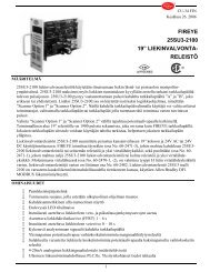
InSight Scanners, 95IR, 95UV, 95DS<br />
The FIREYE InSight Type 95IR, 95UV, and 95DS<br />
flame scanners are micro-processor based flame scanners<br />
utilizing solid state infrared (IR) or ultraviolet (UV)<br />
or dual (IR and UV) sensors.<br />
The FIREYE InSight Type 95 flame scanners incorporate<br />
an internal flame relay with adjustable<br />
ON/OFF thresholds, thereby eliminating the need for a<br />
remote flame amplifier.<br />
The InSight scanners incorporate elements of the<br />
FIREYE Type 45FS1 and 45UVFS1 Signature Scanners<br />
as well as of the Type 45RM4 flame scanners to<br />
detect the presence or absence of a target flame in single<br />
or multi-burner applications.<br />
The InSight scanners measure the amplitude of the<br />
modulations (the flame “flicker”) that occur within the<br />
targeted flame. During the scanner set-up procedure, the<br />
modulation frequency that yields the best flame ON/<br />
OFF discrimination is selected. The appropriate modulation<br />
frequency and sensor gain is either manually<br />
selected or automatically selected with manual override<br />
capability (AutoTune).<br />
The InSight 95IR, 95UV, and 95DSS2 scanners have<br />
twenty-one choices of modulation frequency, adjustable<br />
sensor gain, adjustable flame relay ON/OFF thresholds,<br />
4-20 mA analog signal strength output, fault relay, and<br />
four selectable programmable files to store setpoints (for<br />
different fuels or firing rates). These scanners also have<br />
remote communications capability via <strong>Fireye</strong> ®<br />
FS950W-1 Windows ® based PC software.<br />
8 FIREYE ® System Components
InSight Scanners, 95IR,95UV, 95DS<br />
All InSight scanner models are powered by 24 VDC<br />
and contain electronic self-checking (no mechanical<br />
shutter required). InSight scanners are available witih<br />
a twelve-pin male electrical disconnect (standard), or<br />
with ten feet of captive cable and no connector (“CG”<br />
models). The scanners contain an eight character alphanumeric<br />
LED display and a four (4) push-button keypad<br />
to enable the user to view operating parameters and<br />
select setpoints.<br />
Scanner accessories include 24 VDC power supplies,<br />
pre-fabricated cable assemblies, harness assemblies and<br />
mounting flanges. Refer to bulletins CU-95, CU-96,<br />
CU-97 and CU-100.<br />
TYPE/MODEL<br />
95IRS2-1<br />
FREQ.<br />
HZ.<br />
WAVELENGTH<br />
(nanometers)<br />
MOUNT<br />
THREADS<br />
700-1700 1” NPT<br />
AMBIENT<br />
TEMP. MAX.,<br />
MIN.<br />
SAFETY<br />
APPROVALS<br />
ULC/US, FM<br />
95IRS2E-1 (P/N 60-2692) or<br />
DIN-DVGW, CE<br />
95UVS2-1<br />
95UVS2E-1<br />
24 VDC<br />
295-320<br />
1” BSP<br />
(P/N 60-2693)<br />
mounting flange<br />
150° (65°C)<br />
-40°F (-40°C)<br />
ULC/US, FM<br />
DIN-DVGW, CE<br />
95DSS2-1 295-320 & ordered<br />
ULC/US, FM<br />
95DSS2E-1<br />
700-1700 separately<br />
DIN-DVGW, CE<br />
Recommended Scanner Cable<br />
59-497 12-wire shielded scanner cable.<br />
Accessories<br />
59-497-xxx Pre-fabricated scanner cable with female connector<br />
59-497-xxxR Pre-fabricated scanner cable with right angle female connector<br />
59-497-xxxC Pre-fabricated scanner cable with female connector and flexible<br />
conduit adapter<br />
59-497-xxxRC Pre-fabricated scanner cable with right angle female connector<br />
and flexible conduit adapter<br />
60-2692 1” NPT mounting flange kit, includes 35-127-1 insulating nipple.<br />
60-2963 1” BST mounting flange kit, includes 35-127-3 insulating nipple.<br />
129-164 Female cable quick-disconnect kit<br />
129-164R Female cable quick-disconnect kit, right angle<br />
NOTES<br />
See page 4 for complete<br />
model listing.<br />
129-164C Female cable quick-disconnect kit, with flexible conduit adapter<br />
129-164RC Female cable quick-disconnect kit, right angle with flexible conduit<br />
adapter.<br />
FIREYE ® System Components 9
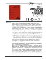
Phoenix Scanners 85UVF and IRF<br />
The <strong>Fireye</strong> Phoenix type 85UVF/IRF flame scanners<br />
are microprocessor based devices utilizing a solid state<br />
flame detection sensor. The Phoenix flame scanners incorporate<br />
an internal flame relay with automatically set ON/<br />
OFF thresholds, thereby eliminating the need for a remote<br />
flame amplifier or flame switch.<br />
Phoenix scanners detect the amplitude of the modulations<br />
(the flame “flicker”) that occur within the targeted<br />
flame, over a wide frequency. During the scanner setup<br />
procedure, the amplitudes of the target flame are automatically<br />
stored by the flame scanner, together with optimum<br />
ON/OFF criteria. The appropriate sensor gain is automatically<br />
selected. Phoenix scanners incorporate full self diagnostics<br />
and electronic self checking.<br />
The Phoenix 85UVF/IRF is available in multiple models differentiated by detection cell type, levels of<br />
hazardous area certifications and agency approvals.<br />
The Phoenix 85UVF/IRF flame scanner is powered by 24Vdc. Electrical connection is via an 8-pin electrical<br />
quick-disconnect (QD). An analog 4 to 20mA output of flame strength is standard.<br />
Operator interface to the Phoenix scanner is via a pushbutton keypad and informative LEDs. These provide<br />
continuous indication of flame signal, flame relay status, scanner status as well as selected mode of operation.<br />
Simplified keystroke routines are used for setup and this can be completed in seconds. For remote<br />
interface, outputs are provided for flame switch, fault relay and 4 to 20mA flame strength.<br />
Note: The Phoenix QD models with electrical quick-disconnect have replaced the original models<br />
equipped with ten feet of captive cable. The QD models (with 59-546-x cables) are suitable for use in Class<br />
I Division 2 hazardous areas, thereby eliminating the need for "EX" models. The "CEX" models remain<br />
unchanged for use in EEx d IIC T6 hazardous areas.<br />
Refer to bulletins CU-114 and CU-115.<br />
TYPE/MODEL<br />
85IRF1-1QD<br />
85IRF4-1QDWR<br />
85UVF1-1QD<br />
FREQ.<br />
HZ.<br />
24 VDC<br />
WAVELENGTH<br />
(nanometers)<br />
10 FIREYE ® System Components<br />
MOUNTING<br />
FLANGE<br />
700-1700 1” NPT<br />
(P/N 35-318-1)<br />
or<br />
295-320 1” BSP<br />
85UVF4-1QDWR (P/N 35-318-2)<br />
ordered<br />
separately<br />
AMBIENT<br />
TEMP. MAX.,<br />
MIN.<br />
150 (65 C)<br />
-40 F (-40 C)<br />
SAFETY<br />
APPROVALS<br />
UL C/US, FM,<br />
DIN, CE<br />
UL C/US, FM<br />
UL C/US, FM,<br />
DIN, CE<br />
UL C/US, FM<br />
NOTES<br />
See page 5 for complete<br />
model listing.
Signature Scanner Type 45FS1 and 45UVFS1<br />
The <strong>Fireye</strong> Type 45FS1 (Infrared), Type 45UVFS1<br />
(Ultraviolet) <strong>Flame</strong> Signature Scanner incorporates an<br />
innovative flame detection method to determine the presence<br />
or absence of a target flame in a single or multiburner<br />
environment. Both scanners use a software algorithm<br />
that constantly compares the real-time amplitudefrequency<br />
characteristics of the target flame with the<br />
amplitude-frequency characteristics that it learned during<br />
setup, called the signature of the target flame. The 45FS1/<br />
45UVFS1 scanners have an eight (8) character LED<br />
display and three (3) push-button keypad to program or<br />
review various system setpoints and operating parameters.<br />
The 45FS1/45UVFS1 flame scanners can communicate<br />
remotely both to review and to program the system<br />
setpoints as well as download and upload the “learned”<br />
flame signature data from one scanner to another. This is<br />
accomplished with an IBM compatible PC and the<br />
FS700W-1 (Windows ® ) software program. Fiber optic<br />
versions and explosion proof housing versions are available.<br />
Refer to Bulletins CU-32, CU-33, CU-39 and CU-40.<br />
FIREYE ® System Components 11
Signature Scanner Type 45FS1 and 45UVFS1<br />
TYPE/MODEL<br />
SUPPLY<br />
VOLTAGE<br />
Replacement Parts<br />
61-2275-3 Glass lens assembly for 45FS1.<br />
61-2275-4<br />
129-127-6<br />
Quartz lens assembly for 45UVFS1.<br />
Female quick-disconnect kit, includes 1 Recommended Scanner Cable<br />
/ 2 " flexible conduit adapter.<br />
59-470 6-wire shielded scanner cable.<br />
59-471 8-wire shielded scanner cable. (For remote communication.)<br />
Accessories<br />
61-6671-10 10 foot Wiring Harness (See bulletin CU-40).<br />
61-6671-15 15 foot Wiring Harness (See bulletin CU-40).<br />
61-6671-20 20 foot Wiring Harness (See bulletin CU-40).<br />
61-6671-30 30 foot Wiring Harness (See bulletin CU-40).<br />
61-6702 Adapter kit to mount 61-6625 or 61-6694 fiber optic scanner onto<br />
Detector Electronics fiber optic assemblies (consult factory).<br />
EC485 RS485/RS232 Adapter with 120 VAC Power supply<br />
IC485 RS485/RS232 Optically isolated adapter with 120 VAC power<br />
supply<br />
UC485 USB to RS-485 Optically isolated adapter (USB powered)<br />
FS700W-1 Windows ® communication software for IBM compatible PC.<br />
Allows PC to communicate with up to 128 45FS1/45UVFS1.<br />
See bulletin CU-56.<br />
12 FIREYE ® System Components<br />
WAVELENGTH<br />
(nanometers)<br />
MOUNT<br />
THREADS<br />
AMBIENT<br />
TEMP. MAX.,<br />
MIN.<br />
SAFETY<br />
APPROVALS<br />
45FS1-1000<br />
700-2,500 1" NPT 150°F (65°C)<br />
45FS1-1001 1" BSP<br />
-4°F (-20°C)<br />
Compatible with all <strong>Fireye</strong> amplifiers<br />
45UVFS1-1000 24VDC 290-390 1" NPT 131°F (55°C) FM listed in Table 2.<br />
45UVFS1-1001 1" BSP<br />
-4°F (-20°C)<br />
SCANNERS WITH EXPLOSION-PROOF HOUSINGS<br />
45FS1-1000CEX<br />
45FS1-1000 mounted in ATEX<br />
700-2,500<br />
150°F (65°C)<br />
approved housing. EExd IIC T6<br />
45FS1-1000EX - 4°F (-20°C)<br />
Class I, Div 1 and 2, Groups C, D;<br />
Class II, Div 1 and 2, Groups E, F, G;<br />
24 VDC<br />
1" NPT<br />
FM Class III approved housing.<br />
45UVFS1-1000CEX<br />
45UVFS1-1000 mounted in ATEX<br />
290-390 131°F (55°C)<br />
approved housing. EExd IIC T6<br />
45UVFS1-1000EX - 4°F (-20°C)<br />
FIBER OPTIC SCANNER<br />
Class I, Div 1 and 2, Groups C, D;<br />
Class II, Div 1 and 2, Groups E, F, G;<br />
Class III approved housing.<br />
61-6625<br />
700-2,500<br />
150°F (65°C) FM Use with glass fiber optic assem-<br />
(45FS1) 24VDC<br />
Fiber Optic - 4°F (-20°C)<br />
blies.<br />
61-6694-1<br />
(45UVFS1)<br />
290-390 131°F (55°C)<br />
- 4°F (-20°C)<br />
FM Must use with quartz fiber optic<br />
assemblies.<br />
NOTES
Background Gain Control (BGC)<br />
Infrared <strong>Flame</strong> Scanners Type 45RM4<br />
The self-checking 45RM4 infra-red <strong>Flame</strong> Scanner<br />
incorporates several design features making it applicable<br />
to detect and discriminate the presence or absence of flame<br />
for a wide range of fuel types. A 16 position frequency<br />
selector switch allows the user to choose the proper<br />
frequency where the greatest discrimination occurs. A gain<br />
adjustment potentiometer on the scanner allows the user to<br />
adjust the amplification of the flame signal by the scanner.<br />
The user can also enable or disable the background gain<br />
control function via a selector switch. Ten (10) flame<br />
LEDs aid in the sighting and location of the scanner. The<br />
scanner also incorporates a quick disconnect to provide for<br />
ease of installation and removal of the scanner, as well as<br />
24 VDC operation to reduce electrical noise interference.<br />
Fiber optic version and explosion proof housing versions<br />
available.<br />
Refer to Bulletin CU-31.<br />
TYPE/MODEL<br />
SUPPLY<br />
VOLTAGE<br />
WAVELENGTH<br />
(nanometers)<br />
MOUNT<br />
THREADS<br />
AMBIENT<br />
TEMP. MAX.,<br />
MIN.<br />
SAFETY<br />
APPROVALS<br />
NOTES<br />
45RM4-1000<br />
1" NPT<br />
FM, APAVE<br />
45RM4-1001 24 VDC 700-2,500 1" BSP 150°F (65°C)<br />
-40°F (-40°C)<br />
FM, DIN<br />
Compatible with all <strong>Fireye</strong> amplifiers<br />
listed in Table 2.<br />
SCANNERS WITH EXPLOSION-PROOF HOUSINGS<br />
45RM4-1000CEX 24 VDC 700-2,500 1" NPT 150°F (65°C) — 45RM4-1000 mounted in ATEX<br />
-40°F (-40°C)<br />
approved housing. EExd IIC T6.<br />
45RM4-1000EX 24 VDC 700-2,500 1" NPT 150°F (65°C) — Class I, Div 1 and 2, Groups C, D;<br />
-40°F (-40°C)<br />
Class II, Div 1 and 2, Groups E, F, G;<br />
Class III approved housing<br />
FIBER OPTIC SCANNER<br />
61-6521 24VDC 700-2,500 Fiber Optic 150°F (65°C) — For use with glass or quartz fiber optic<br />
Mounting -40°F (-40°C)<br />
assemblies.<br />
Replacement Parts<br />
61-2275-3 Glass lens assembly<br />
129-127-6 Female quick-disconnect kit, includes 1 / 2" flexible conduit adapter.<br />
Recommended Scanner Cable<br />
59-470 6-Wire shielded scanner cable.<br />
FIREYE ® System Components 13
Background Gain Control (BGC)<br />
Infrared <strong>Flame</strong> Scanners Type 45RM2<br />
The self-checking 45RM2 <strong>Flame</strong> Scanner incorporates<br />
design features uniquely suited to detecting individual<br />
flames and discriminating between flame envelopes. They<br />
are similar to the Type 45RM1 scanners but operate further<br />
into the infrared region with a much broader spectral<br />
response. <strong>Flame</strong>s monitored by the 45RM2 may be those<br />
of pulverized coal, oil, natural gas, and flames of other<br />
sources of methane, propane, butane, and other gases.<br />
Fiber optic version and explosion proof housing versions<br />
available.<br />
Refer to Bulletin CU-26.<br />
TYPE/MODEL<br />
FREQ.<br />
HZ.<br />
WAVELENGTH<br />
(nanometers)<br />
Replacement Parts<br />
61-4468-1 Shutter and bracket assembly<br />
61-2275-3 Glass lens assembly<br />
60-1622 Long Range Lens Assembly (for use when scanner is greater<br />
than 12 feet from flame, e.g. kiln applications).<br />
60-2366 Quick disconnect kit, includes 1/2" flexible conduit adapter.<br />
<strong>Inc</strong>ludes both male and female connectors.<br />
Recommended Scanner Cable<br />
59-470 6-Wire shielded scanner cable.<br />
14 FIREYE ® System Components<br />
MOUNT<br />
THREADS<br />
AMBIENT<br />
TEMP. MAX.,<br />
MIN.<br />
SAFETY<br />
APPROVALS<br />
NOTES<br />
45RM2-1000<br />
700-2,500 1" NPT 150°F (65°C) FM, APAVE —<br />
45RM2-1001 50/60<br />
1" BSP<br />
- 40°F (-40°C)<br />
FM, DIN<br />
SCANNERS WITH EXPLOSION-PROOF HOUSINGS<br />
45RM2-1000EX<br />
700-2,500 1" NPT 150°F (65°C) — Class I, Div. 1 and 2, Goups C, D; Class<br />
50/60<br />
-40°F (-40°C)<br />
FIBER OPTIC SCANNERS<br />
II, Div. 1 and 2, Groups E, F, G: Class<br />
III approved housing.<br />
61-5234 50/60 700-2,500 Fiber Optic 150°F (65°C) — For use with glass or quartz fiber optic<br />
Mounting -40°F (-40°C)<br />
assemblies.<br />
All controls in this table are compatible with all <strong>Fireye</strong> amplifiers listed in Table 2.<br />
When these scanners are used with 25SU3-2100, a 19UVPS-2120 or -2220, or 19MPS-2000 power supply is required.
Background Gain Control (BGC)<br />
Infrared <strong>Flame</strong> Scanners Type 45RM1<br />
The self-checking 45RM1 <strong>Flame</strong> Scanner incorporates<br />
a number of unique features to provide excellent flame<br />
detection and discrimination when firing pulverized coal,<br />
oil or other fuels which radiate visible light during the<br />
combustion process. Outstanding operation is achieved by<br />
combining a background gain control amplifier, adjustable<br />
gain control potentiometer, and threshold detector to yield<br />
a unit which automatically adapts its sensitivity to the<br />
firing conditions and provides a clear indication of flame<br />
presence or absence in spite of surrounding radiation<br />
sources. Fiber optic version and explosion proof housing<br />
versions available.<br />
Refer to Bulletin CU-26.<br />
TYPE/MODEL<br />
FREQ.<br />
Hz<br />
Replacement Parts<br />
WAVELENGTH<br />
(nanometers)<br />
MOUNT<br />
THREADS<br />
AMBIENT<br />
TEMP. MAX.,<br />
MIN.<br />
SAFETY<br />
APPROVALS<br />
61-4468-1 Shutter and bracket assembly<br />
61-2275-3 Glass lens assembly<br />
60-1622 Long range lens assembly (for use when scanner is greater<br />
than 12 feet from flame, e.g. kiln applications).<br />
60-2366 Quick disconnect kit, includes 1/2" flexible conduit adapter.<br />
<strong>Inc</strong>ludes both male and female connectors.<br />
Recommended Scanner Cable<br />
59-470 6-Wire sheilded scanner cable.<br />
NOTES<br />
(see below also)<br />
45RM1-1001 50/60 450-1,000 1" NPT 150°F (65°C) FM<br />
45RM1-1003 1" BSP<br />
- 40°F (-40°C)<br />
FM, DIN<br />
SCANNERS WITH EXPLOSION-PROOF HOUSINGS<br />
45RM1-1001EX 50/60 450-1,000 1" NPT 150°F (65°C)<br />
Class I, Div. 1 and 2, Groups C, D; Class II, 1<br />
- 40°F (-40°C)<br />
FIBER OPTIC SCANNER<br />
— and 2, Groups E, F, G; Class III approved<br />
housing.<br />
61-4892-2 50/60 450-1000 Fiber Optic 150°F (65°C) — Use with glass IR Fiber Optic assemblies.<br />
Mounting - 40°F (-40°C)<br />
All Models in this table are compatible with all <strong>Fireye</strong> amplifiers listed in Table 2.<br />
When these scanners are used with 25SU3-2100, a 19UVPS-2120 or -2220, or 19MPS-2000 power supply is required.<br />
FIREYE ® System Components 15
Ultraviolet <strong>Flame</strong> Scanners Type 45UV5<br />
The 45UV5 Scanner detects the presence of flames<br />
which emit ultraviolet radiation (UV). Typical fossil fuels<br />
which emit UV include natural gas, coke oven gas,<br />
propane, methane, kerosene, light petroleum distillates and<br />
diesel fuels. These scanners incorporate a built-in selfchecking<br />
mechanism to protect against UV tube malfunctions.<br />
The scanners are available with explosion proof<br />
housings.<br />
Refer to Bulletin CU-22.<br />
TYPE/MODEL<br />
Replacement Parts<br />
FREQ.<br />
Hz<br />
WAVELENGTH<br />
(Nanometers)<br />
16 FIREYE ® System Components<br />
MOUNT<br />
THREADS<br />
AMBIENT<br />
TEMP. MAX.,<br />
MIN.<br />
SAFETY<br />
APPROVALS<br />
4-290-2 UV tube (for scanner Engineering codes 04 and higher)<br />
61-2275-2 Quartz lens assembly<br />
61-2841-1 NPT hinged flange<br />
61-2841-2 BSP hinged flange<br />
61-2913-1 Shutter, bracket, and lens assembly (for scanner Engineering<br />
codes 00 through 03)<br />
61-7203 Shutter, bracket, and lens assembly (for scanner Engineering codes<br />
04 and higher).<br />
61-2914-1 Shutter and bracket assembly<br />
60-2366 Quick disconnect kit, includes 1/2" flexible conduit adapter.<br />
<strong>Inc</strong>ludes both male and female connectors.<br />
Recommended Scanner Cable<br />
59-470 6-Wire shielded scanner cable.<br />
NOTES<br />
45UV5-1000 60<br />
1" NPT<br />
FM, APAVE Compatible with 25SU3-4169T con-<br />
45UV5-1010 60<br />
180-250<br />
1" BSP<br />
200°F (93°C)<br />
FM<br />
trols with Engineering Code 18 or<br />
higher<br />
45UV5-1101 50 1" BSP<br />
- 40°F (-40°C)<br />
FM, DIN Compatible with 25SU3-4169T controls<br />
with Engineering Code lower than<br />
18.<br />
SCANNERS WITH EXPLOSION-PROOF HOUSINGS<br />
45UV5-1101CEX 50<br />
1" BSP<br />
— 45UV5-1101 mounted in ATEX<br />
approved housing. EExd IIC T6.<br />
45UV5-1000CEX 60 1" NPT<br />
200°F (93°C)<br />
— 45UV5-1000 mounted in ATEX<br />
approved housing.EExd IIC T6.<br />
45UV5-1101EX 50<br />
180-250<br />
1" BSP - 40°F (-40°C) — Class I, Div. 1 and 2, Groups C, D: Class<br />
II, Div. 1 and 2, Groups E, F, G: Class III<br />
approved housing.<br />
45UV5-1000EX 60 1" NPT — Class I, Div. 1 and 2, Groups C, D: Class<br />
II, Div. 1 and 2, Groups E, F, G: Class III<br />
approved housing.<br />
All Models in this table are compatible with all <strong>Fireye</strong> amplifiers listed in Table 5.<br />
When these scanners are used with 25SU3-2100, a 19UVPS-2120 or -2220, or 19MPS-2000 power supply is required.
Fiber Optic Scanners and Fiber Optic Sub-Assemblies<br />
<strong>Fireye</strong> offers fiber optic versions of the 45RM1,<br />
45RM2, 45RM4, 45FS1, 45UVFS1, 85IR, 85UV, 95IR<br />
and 95UV scanners. They have been designed for<br />
applications where liquid and solid fuel burners have<br />
movable vanes, air compartments or burner nozzles that<br />
would, in some positions, obscure a line of sight or<br />
move the flame pattern out of the field of view of a surface<br />
mounted scanner.<br />
Specifications<br />
MOUNTING TEMPERATURE PURGE AIR LENS<br />
Optics mounted in outer carrier tube with a<br />
303 stainless steel hexagonal mounting head,<br />
1 1 / 2 " (38.1mm) across flats, which is tack<br />
welded to an air compartment nozzle parallel<br />
to the fuel flow.<br />
ELECTRONICS:<br />
Models 45RM1, 45RM2, 45RM4:<br />
-40° F (-40° C) min.,<br />
150°F (65°C) max.<br />
Model 45FS1: -4°F (-20°C) min., 150F<br />
(65° C) max.<br />
Model 45UVFS1: -4°F (-20°C) min.,<br />
131F (55° C) max.<br />
FIBER OPTICS:<br />
800°F (427°C) max. glass,<br />
752°F (400°C) max. quartz.<br />
Fiber optic scanners consist of three sub-assemblies:<br />
Scanner Electronics Assembly, Inner Carrier Assembly<br />
(includes the “A,” “B,” and “C” lens and fiber optic bundle<br />
either glass or quartz), and Outer Carrier Assembly. Order<br />
by specifying the part number for each sub-assembly. See<br />
the appropriate tables on the following pages.<br />
Example: A customer wants a 9 foot quartz fiber<br />
optic assembly using a 95UVS2 type scanner. They must<br />
order the following three parts:<br />
1. 61-7080-9 Inner Carrier Assembly, 9 ft., with quartz optics.<br />
2. 61-5386 Outer Carrier Assembly, 9 ft.<br />
3. 95UVS2-2 Scanner Type 95UVS2<br />
4-15 SCFM (113-425<br />
L/M) at either the 1”<br />
NPT or 3/8” NPT tap.<br />
Minimum applied pressure<br />
should be either<br />
15” w.c. above firebox<br />
pressure at 1” NPT tap<br />
or 25” w.c. above furnace<br />
pressure at 3/8”<br />
tap..<br />
High temperature<br />
glass or quartz.<br />
FIREYE ® System Components 17
Fiber Optic Sub-Assemblies, 45 - Series Scanners<br />
SCANNER ELECTRONICS TYPE PART NUMBER BULLETIN<br />
45RM1(VIS/IR) 61-4892-2 CU-26, CU-21<br />
45RM2 (IR) 61-5234 CU-26, CU-21<br />
45RM4 (IR) 61-6521 CU-31, CU-21<br />
45FS1 (IR) 61-6625 CU-32, CU-21<br />
45UVFS1 (UV) 61-6694-1 CU-32, CU-21<br />
OUTER CARRIER ASSEMBLY<br />
(USE WITH GLASS OR QUARTZ)<br />
*Note: The “Nominal Length” refers to the approximate length of the overall assembly, including the installed electronics.<br />
Refer to dimensions “A” through “F”in bulletin CU-21 to determine the nominal length that best suits your application.<br />
**Glass optics are recommended for 45RM1, 45RM2, 45RM4 and 45FS1.<br />
**Quartz optics are required for 45UVFS1 are also suitable for for 45RM2, 45RM4 and 45FS1 for increased signal strength.<br />
18 FIREYE ® System Components<br />
(GLASS) INNER<br />
CARRIER ASSEMBLY<br />
(QUARTZ) INNER<br />
CARRIER ASSEMBLY<br />
NOMINAL LENGTH* feet (meters) PART NUMBER PART NUMBER** PART NUMBER**<br />
3 (0.9) 61-6647 61-4894-7 61-6856-3<br />
5 (1.5) 61-5430 61-4894-3 61-6856-5<br />
6 (1.8) 61-6845 61-4894-8 61-6856-6<br />
7 (2.1) 61-4893 61-4894-1 61-6856-7<br />
9 (2.7) 61-5386 61-4894-2 61-6856-9<br />
10 (3.0) 61-6305 61-4894-4 61-6856-10<br />
12 (3.7) 61-6306 61-4894-5 61-6856-12<br />
14 (4.3) 61-6540 61-4894-6 61-6856-14<br />
FIBER OPTIC BUNDLE<br />
REPLACEMENT PARTS<br />
GLASS BUNDLE QUARTZ BUNDLE<br />
NOMINAL LENGTH * feet (meters) PART NUMBER** PART NUMBER**<br />
3 (0.9) 61-4842-7 61-6872-3<br />
5 (1.5) 61-4842-3 61-6872-5<br />
6 (1.8) 61-4842-9 61-6872-6<br />
7 (2.1) 61-4842-1 61-6872-7<br />
9 (2.7) 61-4842-2 61-6872-9<br />
10 (3.0) 61-4842-4 61-6872-10<br />
12 (3.7) 61-4842-5 61-6872-12<br />
14 (4.3) 61-4842-6 61-6872-14<br />
LENS HOLDER GLASS LENS QUARTZ LENS<br />
LENS SKEW PART NUMBER PART NUMBER<br />
0 deg. skew 61-4895 (“A”) 61-6754 (“AA”)<br />
5 deg. skew 61-4913 (“B”) 61-6864 (“AB”)<br />
9 deg. skew 61-4914 (“C”) 61-6865 (“AC”)
Fiber Optic Sub-Assemblies, 85 - Series Phoenix Scanners<br />
SCANNER ELECTRONICS TYPE PART NUMBER BULLETIN<br />
Phoenix (IR) 85IRF1-2QD CU-114, CU-115<br />
Phoenix (UV) 85UVF1-2QD CU-114, CU-115<br />
Phoenix (IR), Special applications<br />
85IRF4-2QDWR CU-114, CU-115, 133-<br />
(For use with EDC1, EDC2, or MEDC2 direct-coupled amplifiers).<br />
732, 133-733<br />
Phoenix (UV), Special applications<br />
85UVF4-2QDWR CU-114, CU-115, 133-<br />
(For use with EDC1, EDC2, or MEDC2 direct-coupled amplifiers).<br />
732, 133-733<br />
OUTER CARRIER ASSEMBLY<br />
(USE WITH GLASS OR QUARTZ)<br />
(GLASS) INNER<br />
CARRIER ASSEMBLY<br />
(QUARTZ) INNER<br />
CARRIER ASSEMBLY<br />
NOMINAL LENGTH* feet (meters) PART NUMBER PART NUMBER** PART NUMBER**<br />
3 (0.9) 61-6647 61-7065-3 61-7064-3<br />
5 (1.5) 61-5430 61-7065-5 61-7064-5<br />
6 (1.8) 61-6845 61-7065-6 61-7064-6<br />
7 (2.1) 61-4893 61-7065-7 61-7064-7<br />
9 (2.7) 61-5386 61-7065-9 61-7064-9<br />
10 (3.0) 61-6305 61-7065-10 61-7064-10<br />
12 (3.7) 61-6306 61-7065-12 61-7064-12<br />
14 (4.3) 61-6540 61-7065-14 61-7064-14<br />
FIBER OPTIC BUNDLE<br />
REPLACEMENT PARTS<br />
GLASS BUNDLE QUARTZ BUNDLE<br />
NOMINAL LENGTH * feet (meters) PART NUMBER** PART NUMBER**<br />
3 (0.9) 61-4842-7 61-6872-3<br />
5 (1.5) 61-4842-3 61-6872-5<br />
6 (1.8) 61-4842-9 61-6872-6<br />
7 (2.1) 61-4842-1 61-6872-7<br />
9 (2.7) 61-4842-2 61-6872-9<br />
10 (3.0) 61-4842-4 61-6872-10<br />
12 (3.7) 61-4842-5 61-6872-12<br />
14 (4.3) 61-4842-6 61-6872-14<br />
LENS HOLDER GLASS LENS QUARTZ LENS<br />
LENS SKEW PART NUMBER PART NUMBER<br />
0 deg. skew 61-4895 (“A”) 61-6754 (“AA”)<br />
5 deg. skew 61-4913 (“B”) 61-6864 (“AB”)<br />
9 deg. skew 61-4914 (“C”) 61-6865 (“AC”)<br />
*Note: The “Nominal Length” refers to the approximate length of the overall assembly, including the installed electronics.<br />
Refer to dimensions “A” through “F”in bulletin CU-115 to determine the nominal length that best suits your application.<br />
**Glass optics are recommended for 85IR.<br />
**Quartz optics are required for 85UV.<br />
FIREYE ® System Components 19
Fiber Optic Sub-Assemblies, 95 - Series InSight Scanners<br />
SCANNER ELECTRONICS TYPE PART NUMBER BULLETIN<br />
InSight (IR) 95IRS2-2 CU-95, CU-101<br />
InSight (IR) 95IRS2-2CG CU-95, CU-101<br />
InSight (UV) 95UVS2-2 CU-95, CU-101<br />
InSight (UV) 95UVS2-2CG CU-95, CU-101<br />
InSight (IR), CE 95IRS2E-2 CU-95, CU-101<br />
InSight (IR), CE 95IRS2E-2CG CU-95, CU-101<br />
InSight (UV), CE 95UVS2E-2 CU-95, CU-101<br />
InSight (UV), CE 95UVS2E-2CG CU-95, CU-101<br />
OUTER CARRIER ASSEMBLY<br />
(USE WITH GLASS OR QUARTZ)<br />
*Note: The “Nominal Length” refers to the approximate length of the overall assembly, including the installed electronics.<br />
Refer to dimensions “A” through “F”in bulletin CU-101 to determine the nominal length that best suits your application.<br />
**Glass optics are recommended for 95IR.<br />
**Quartz optics are required for 95UV.<br />
20 FIREYE ® System Components<br />
(GLASS) INNER<br />
CARRIER ASSEMBLY<br />
(QUARTZ) INNER<br />
CARRIER ASSEMBLY<br />
NOMINAL LENGTH* feet (meters) PART NUMBER PART NUMBER** PART NUMBER**<br />
3 (0.9) 61-6647 61-6960-3 61-7080-3<br />
5 (1.5) 61-5430 61-6960-5 61-7080-5<br />
6 (1.8) 61-6845 61-6960-6 61-7080-6<br />
7 (2.1) 61-4893 61-6960-7 61-7080-7<br />
9 (2.7) 61-5386 61-6960-9 61-7080-9<br />
10 (3.0) 61-6305 61-6960-10 61-7080-10<br />
12 (3.7) 61-6306 61-6960-12 61-7080-12<br />
14 (4.3) 61-6540 61-6960-14 61-7080-14<br />
FIBER OPTIC BUNDLE<br />
REPLACEMENT PARTS<br />
GLASS BUNDLE QUARTZ BUNDLE<br />
NOMINAL LENGTH * feet (meters) PART NUMBER** PART NUMBER**<br />
3 (0.9) 61-4842-7 61-6872-3<br />
5 (1.5) 61-4842-3 61-6872-5<br />
6 (1.8) 61-4842-9 61-6872-6<br />
7 (2.1) 61-4842-1 61-6872-7<br />
9 (2.7) 61-4842-2 61-6872-9<br />
10 (3.0) 61-4842-4 61-6872-10<br />
12 (3.7) 61-4842-5 61-6872-12<br />
14 (4.3) 61-4842-6 61-6872-14<br />
LENS HOLDER GLASS LENS QUARTZ LENS<br />
LENS SKEW PART NUMBER PART NUMBER<br />
0 deg. skew 61-4895 (“A”) 61-6754 (“AA”)<br />
5 deg. skew 61-4913 (“B”) 61-6864 (“AB”)<br />
9 deg. skew 61-4914 (“C”) 61-6865 (“AC”)
<strong>Flame</strong> Scanner Accessories<br />
PART NUMBER DESCRIPTION<br />
4-290-2 UV tube for 45UV5 scanners, Engineering code 04 and higher only.<br />
16-103 Lens retainer for all scanners (orange bushing).<br />
34-181 Retaining Ring for orifice (53-121)<br />
35-127-1 Heat insulating Nipple (1" NPT threads)<br />
35-127-3 Heat insulating Nipple (1" BSP threads)<br />
35-200 1" “Y” connector (NPT)<br />
35-201 1" Close Nipple (NPT)<br />
35-202 3/8” Plug (NPT)<br />
35-240 1 inch close nipple (BSP)<br />
46-4 Lens for long range lens assembly 60-1622.<br />
46-38 Quartz lens for 45UV5 scanner.<br />
46-87 Lens for 45RM1, 45RM2, 45RM4, and 45FS1 scanners<br />
46-179 Quartz lens for 45UVFS1 scanner.<br />
53-121 #2 through 10 orifice plate set for all scanners, includes 34-181 retaining ring.<br />
60-1199 Sealing union with quartz window (1" NPT)<br />
60-1622 Long range lens assembly for 45RM1, 45RM2, 45RM4, 45FS1 scanners<br />
60-1664-3 Swivel mount (NPT threads)<br />
60-1664-4 Swivel mount (BSP threads)<br />
60-2366 Quick-disconnect kit for 45UV5, 45RM1, 45RM2 (male and female connectors).<br />
61-2275-2 Quartz lens assembly for 45UV5.<br />
61-2275-3 Glass lens assembly for 45RM1, 45RM2, 45RM4, 45FS1.<br />
61-2275-4 Quartz lens assembly for 45UVFS1.<br />
61-2841-1 NPT hinged flange for 45UV5.<br />
61-2841-2 BSP hinged flange for 45UV5.<br />
61-2913-1 Shutter, gasket, bracket, and lens assembly for 45UV5 (includes 61-2914-1).Engineering codes 00 thru 03 only.<br />
61-7203 Shutter, gasket, bracket, and lens assembly for 45UV5 (includes 61-2914-1) for Engineering code 04 and higher only.<br />
61-2914-1 Shutter and bracket assembly only for 45UV5.<br />
61-4468 Shutter and bracket assembly for 45RM1, 45RM2.<br />
82-95 Lens Holder for all scanners (orange grommet).<br />
92-48 Quartz Window for P.N. 60-1199.<br />
101-78 Diode (use when combining 45UV5 with 45RM scanners).<br />
129-127-6 Female quick-disconnect kit (with 1/2 inch flexible conduit adapter) for 45RM4, 45FS1, 45UVFS1 scanners.<br />
FIREYE ® System Components 21
<strong>Flame</strong> Scanner Cables<br />
PART NUMBER DESCRIPTION<br />
59-470 6-wire with special shield around all wires. For use with all scanners. Specify length. Cable shipping weight:<br />
12 lbs./100 ft. 4.5 kg/25m.<br />
59-471 8-wire with special shield around all wires. For use with 45FS1 and remote communications. Specify length.<br />
Cable shipping weight: 12 lbs / 100 ft. 4.5 kg/ 25m.<br />
59-470-XXX 59-470 cable pre-wired with the female quick disconnect for use with 45RM4, 45FS1, 45UVFS1 scanners.<br />
Available in varying lengths up to 200 feet.<br />
59-471-XXX 59-471 cable pre-wired with the female quick disconnect for use with 45RM4, 45FS1, 45UVFS1 scanners.<br />
Available in varying lengths up to 200 feet.<br />
60-6671-X Wiring harness for 45FS1/45UVFS1 scanners. <strong>Inc</strong>ludes junction box and 59-471 cable in flexible conduit. Available<br />
in lengths up to 40 feet.<br />
59-497 12 conductor cable for InSight and Phoenix scanners<br />
59-497-xxx 59-497 cable, pre-wired with straight female quick-disconnect for use with InSight scanners (non "CG" models).<br />
Available in varying lengths up to 300 feet.<br />
59-497-xxxR 59-497 cable, pre-wired with right-angle female quick-disconnect for use with InSight scanners (non "CG"<br />
models). Available in varying lengths up to 300 feet.<br />
59-497-xxxC 59-497 cable, pre-wired with straight female quick-disconnect and flexible conduit adapter for use with InSight<br />
scanners (non "CG" models). Available in varying lengths up to 300 feet.<br />
59-497-xxxxRC 59-497 cable, pre-wired with right-angle female quick-disconnect and flexible conduit adapter for use with<br />
InSight scanners (non "CG" models). Available in varying lengths up to 300 feet.<br />
59-497-020-WR 59-497 cable, pre-wired with straight female quick-disconnect. For use with InSight scanners (non "CG" models)<br />
and direct-coupled amplifiers only (EDC1, EDC2, MEDC2). Available in 20-foot length only.<br />
59-497-020R-WR 59-497 cable, pre-wired with right-angle female quick-disconnect. For use with InSight scanners (non "CG"<br />
models) and direct-coupled amplifiers only (EDC1, EDC2, MEDC2). Available in 20-foot length only.<br />
59-497-020C-WR 59-497 cable, pre-wired with straight female quick-disconnect and flexible conduit adapter. For use with InSight<br />
scanners (non "CG" models) and direct-coupled amplifiers only (EDC1, EDC2, MEDC2). Available in 20-foot<br />
length only.<br />
59-497-020RC-WR 59-497 cable, pre-wired with right-angle female quick disconnect and flexible conduit adapter. For use with<br />
InSight scanners (non "CG" models) and direct-coupled amplifiers only (EDC1, EDC2, MEDC2). Available in<br />
20-foot length only.<br />
60-2771 Junction box with twelve terminals for Simplicity, Phoenix, and InSight scanners<br />
61-6944-xxx Wiring harness for InSight scanners (non "CG" models). <strong>Inc</strong>ludes junction box and 59-497 cable in flexible<br />
conduit, with straight female quick-disconnect. Available in various lengths up to 50 feet.<br />
61-6944-xxxR Wiring harness for InSight scanners (non "CG" models). <strong>Inc</strong>ludes junction box and 59-497 cable in flexible<br />
conduit, with right-angle female quick-disconnect. Available in various lengths up to 50 feet.<br />
22 FIREYE ® System Components
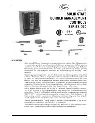
Control Type 25SU5 Model 5011, 5012, 5013,<br />
Control Type 25SU3 Model 5166, 5168<br />
<strong>Fireye</strong> Type 25SU5 Model 5011, 5012, 5013 and Type<br />
25SU3 Model 5166, 5168 <strong>Controls</strong> are surface mounted<br />
controls used in conjunction with Type 45UV5, 45RM,<br />
45FS, 45UVFS <strong>Flame</strong> Scanners. These controls and scanners<br />
comprise a repetitive self-checking system that<br />
confirms flame presence and absence to provide reliable<br />
ignition and flame failure protection. When combined with<br />
appropriate auxiliary devices, these controls enable<br />
construction of integrated safety interlock systems for<br />
single and multiple industrial burner applications firing<br />
gas, oil, pulverized coal, or a combination of fuels continuously.<br />
The 5011, 5012, 5013, 5166, and 5168 <strong>Controls</strong><br />
may also be installed in the safety control circuits of supervised<br />
manual, semi-automatic, and fully automatic burner<br />
management systems as the primary safety control. Wiring<br />
Base required: P/N 60-2206-1 (5011, -5012, -5013), P/N<br />
6-2206-2 (5166, -5168).<br />
These flame safeguard controls monitor flame to<br />
supervise burner and pilot performance throughout the<br />
entire burner load range. Features include <strong>Flame</strong> Relay,<br />
Master Relay (Type 25SU5 only), 0-3 VDC Output, 2<br />
scanner operation.<br />
Optional Display Module, P/N 60-2205: <strong>Inc</strong>ludes Bar<br />
Graph Display, Marginal Alarm with LED, <strong>Flame</strong> Relay<br />
LED, and 0-20mA DC output.<br />
SHOWN WITH OPTIONAL 60-2205 DISPLAY MODULE<br />
CONTROL CHASSIS AMPLIFIER<br />
WIRING BASE<br />
(Ordered Separately)<br />
SENSITIVITY<br />
25SU5-5011 60-2204-2 60-2207-1 60-2206-1 High Sensitivity<br />
25SU5-5012 60-2204-2 60-2207-2 60-2206-1 High Discrimination<br />
25SU5-5013 60-2204-2 60-2207-3 60-2206-1 High Sensitivity/ Low Hysteresis<br />
25SU3-5166 60-2203-2 60-2207-2 60-2206-2 High Discrimination<br />
25SU3-5168 60-2203-2 60-2207-1 60-2206-2 High Sensitivity<br />
All controls include a dust cover (60-2223), blank display module (60-2301) and mounting screw (48-1805)<br />
Note: <strong>Flame</strong> Amplifier Modules 60-2207-1, -2, -3 are operative in either of the chassis. The 60-2207-1 is a high sensitivity<br />
(flame amplification characteristics) amplifier for use on single burner applications with little or no background radiation.<br />
The 60-2207-2 is a high discrimination amplifier for use on single or multi-burner applications where background<br />
radiation is present (e.g. adjacent flame tips, hot refractory, etc.). The 60-2207-3 has the sensitivity of the 60-2207-1 but<br />
without the flame relay on:off hysteresis. This is suitable for applications where there is a very small difference between<br />
flame on and flame off signal strength.<br />
FIREYE ® System Components 23
Control Type 25SU5 Model 5011, 5012, 5013,<br />
Control Type 25SU3 Model 5166, 5168<br />
TYPE/MODEL<br />
SUPPLY<br />
VOLTAGE<br />
50/60 Hz<br />
MAXIMUM<br />
FLAME FAILURE<br />
RESPONSE TIME<br />
(FFRT)<br />
25SU5-5011 120 VAC 1 sec., 4 sec.<br />
Selectable<br />
25SU5-5012 120 VAC 1 sec., 4 sec.<br />
Selectable<br />
25SU5-5013 120 VAC 1 sec., 4 sec.<br />
Selectable<br />
25SU3-5166 120 or<br />
230 VAC<br />
25SU3-5168 120 or<br />
230 VAC<br />
3, 2, 1 sec.<br />
Selectable<br />
3, 2, 1 sec.<br />
Selectable<br />
Type 25SU5 and 25SU3 Control Parts and Accessories<br />
24 FIREYE ® System Components<br />
NOMINAL<br />
SHUTTER<br />
TOTAL CYCLE<br />
PERIOD<br />
AMBIENT<br />
TEMP. MAX.,<br />
MIN.<br />
0.50/4.5 125°F (52°C)<br />
32°F (0°C)<br />
0.50/4.5 125°F (52°C)<br />
32°F (0°C)<br />
0.50/4.5 125°F (52°C)<br />
32°F (0°C)<br />
0.50/4.5 140°F (60°C)<br />
32°F (0°C)<br />
0.50/4.5 140°F (60°C)<br />
32°F (0°C)<br />
SAFETY<br />
APPROVALS<br />
BULLETIN<br />
SHIPPING<br />
WEIGHT<br />
FM CU-27 6 lbs. (2.7 kg)<br />
FM CU-27 6 lbs. (2.7 kg)<br />
FM CU-27 6 lbs. (2.7 kg)<br />
DIN and APAVE CX-742E 6 lbs. (2.7 kg)<br />
DIN and APAVE CX-742E 6 lbs. (2.7 kg)<br />
PART NUMBER DESCRIPTION BULLETIN NUMBER<br />
48-1805 Mounting Screw for 5011/5166 CU-27, CX-742E<br />
60-2203-2 5166, 5168 Chassis CX-742E<br />
60-2204-2 5011, 5012, 5013 Chassis CU-27<br />
60-2205 Display Module CU-27, CX-742E<br />
60-2206-1 5011, 5012, 5013 Wiring Base CU-27<br />
60-2206-2 5166, 5168 Wiring Base CX-742E<br />
60-2207-1 5011, 5168 <strong>Flame</strong> Amplifier Module (High Sensitivity) CU-27, CX-742E<br />
60-2207-2 5012, 5166 <strong>Flame</strong> Amplifier Module (High Discrimination) CU-27, CX-742E<br />
60-2207-3 5013 <strong>Flame</strong> Amplifier Module (High Sensitivity/ Low Hysteresis) CU-27<br />
60-2223 Dust Cover CU-27, CX-742E<br />
60-2301 Blank Display Module CU-27, CX-742E<br />
60-2367 Ribbon cable for 5011, 5012, 5013, 5166, 5168. CU-27, CX-742E
<strong>Flame</strong> Amplifier 25SU3 Model 2100<br />
The <strong>Fireye</strong> Type 25SU3-2100 is a rack-mounted flame<br />
amplifier used in conjunction with Type 45UV51 , 45RM1 ,<br />
45FS, 45UVFS, C9701 and C9707 scanners. The amplifier<br />
and scanners comprise a repetitive self-checking system<br />
that confirms the presence or absence of flame to provide<br />
reliable ignition and flame protection.<br />
Refer to Bulletin CU-34.<br />
Approvals: FM<br />
The 25SU3-2100 incorporates the following design features<br />
to help maximize burner discrimination:<br />
— 4-key keypad, 8 character alpha-numeric display,<br />
and 4 LED indicator lights to review and program<br />
operating parameters and system setpoints.<br />
— Ability to display the flame signal pulses from the<br />
flame scanner(s).<br />
— The flame signal from the flame scanners can be<br />
processed separately or combined in a number of<br />
logical configurations (e.g. AND, OR, etc.).<br />
— Ability to program the pull-in and drop-out thresholds<br />
for the flame relay (DPDT) based on actual<br />
flame signal pulses.<br />
— Programmable marginal alarm relay (SPDT).<br />
— Password protection to prevent unauthorized alteration<br />
of operating setpoints.<br />
The 25SU3-2100 is based on the standard Euro-Card<br />
rack-mounted format, operating on either 24VAC or<br />
24VDC.<br />
1. 45UV5, 45RM1, and 45RM2 require 19UVPS-2120, 19UVPS-2220, or<br />
19MPS-2000 power supply or 192SU3-2120 or -2220 modernization adaptor.<br />
FIREYE ® System Components 25
Type 25SU3-2100 Control Parts and Accessories<br />
PART NUMBER DESCRIPTION<br />
25SU3-2100 <strong>Flame</strong> Amplifier<br />
60-2471-1 Half-rack (includes one 60-2478 Type F connector) 4 slots.<br />
60-2471-3 Full rack (<strong>Inc</strong>ludes one 60-2478 Type F connector) 8 slots.<br />
60-2478 Type F screw terminal straight-style connector (12AWG) for 25SU3-2100.<br />
60-2470-1 110VAC input/24VDC power supply (<strong>Inc</strong>ludes 60-2482) Type H spade connector.<br />
60-2470-2 230VAC input/24VDC power supply (<strong>Inc</strong>ludes 60-2482) Type H spade connector.<br />
60-2530-1 Surface mount rack (refer to bulletin CU-44).<br />
60-2530-2 Surface mount rack with clear hinged cover (refer to bulletin CU-44).<br />
192SU3-2120 120VAC modernization adaptor. Allows 25SU3-2100 amplifier to plug into existing 60-1706, 60-1499,<br />
60E5527, or 60E5528 wiring rack with little or no rewiring.<br />
192SU3-2220 220VAC version of 192SU3-2120<br />
19MPS-2000 Multi-purpose power supply for two (2) 25SU3-2100 amplifiers and up to four (4) low voltage or line voltage<br />
scanners<br />
19UVPS-2120 Power supply (120VAC) required for 45UV5, 45RM1, and 45RM2 flame scanners. (<strong>Inc</strong>ludes 60-2478 type F<br />
screw connector).<br />
19UVPS-2220 Power supply (220VAC) required for 45UV5, 45RM1, and 45RM2 flame scanners. (<strong>Inc</strong>ludes 60-2478 type F<br />
screw connector).<br />
60-2481 Screw terminal, straight style, type H connector for 60-2470-1 and 60-2470-1 power supplies.<br />
60-2482 Spade terminal, straight style, type H connector for 60-2470-1 and 60-2470-2 power supplies.<br />
26 FIREYE ® System Components
Type 60-2530 Surface Mount Wiring Rack<br />
The 60-2530 is a surface mount wiring rack for use<br />
with the 25SU3-2100 (or 25SU3-2000) amplifier. The 60-<br />
2530 wiring rack will hold two (2) 25SU3-2100 amplifiers<br />
and one (1) 19MPS-2000 multi-purpose power supply. The<br />
19MPS-2000 operates on either 120 or 220 VAC input<br />
power, and provides supply voltage to both 25SU3-2100<br />
amplifiers and up to four (4) low voltage (e.g. 45RM4,<br />
45FS1, 45UVFS1, C9701 and C9707) or line voltage (e.g.<br />
45RM1, 45RM2, 45UV5) flame scanners in any combination.<br />
Refer to bulletin CU-45 for detailed information on<br />
19MPS-2000.<br />
Agency Approvals: FM<br />
PART NUMBER DESCRIPTION<br />
60-2530-1 Surface mount wiring rack (accomodates 2 amplifiers, 1 power supply).<br />
60-2530-2 Surface mount wiring rack with clear hinged cover.<br />
60-2490-10 Filler plate.<br />
FIREYE ® System Components 27
Modernization Adapter<br />
192SU3-2120 (120 VAC), 192SU3-2220 (220 VAC)<br />
The <strong>Fireye</strong> 192SU3 Modernization Adapter makes it<br />
easy to upgrade from an existing 25SU3 type amplifiers<br />
using the older style 60-1706, 60-1499, 60E5527, or<br />
60E5528 wiring rack to the <strong>Fireye</strong> 25SU3-2100 amplifier.<br />
The Modernization Adapters provide power to the 25SU3-<br />
2100 from either a 120 VAC (192SU3-2120) or 220 VAC<br />
(192SU3-2220) source.<br />
The 192SU3-2120, -2220 adapter is compatible with<br />
the following <strong>Fireye</strong> flame scanners: 45UV5, 45RM1,<br />
45RM2, 45RM4, and 45FS1 and 45UVFS1.<br />
Note: The 192SU3-2120, -2220 adapters provide power<br />
for the 45UV5, 45RM1, and 45RM2 flame scanners. The<br />
19UVPS-2120, -2220 power supply is not required with<br />
these scanners.<br />
The192SU3-2120, -2220 adapter is directly compatible<br />
(“pin for pin”) with the existing wiring in the 60-1706, 60-<br />
1499, 60E5527, or 60E5528 mounting rack on most applications.<br />
However, on some installations, electrical and/or<br />
mechanical changes may be required (Refer to Bulletin<br />
CU-36).The following table lists the present controls and<br />
the appropriate adapter required to convert that control to<br />
the 25SU3-2100 amplifier.<br />
AMPLIFIER TO UPGRADE<br />
25SU3-4163<br />
ADAPTER PART NUMBER NEW AMPLIFIER<br />
25SU3-4167<br />
25SU3-4170<br />
25SU3-4172<br />
25SU3-5172<br />
25SU3-4167T<br />
25SU3-4171<br />
28 FIREYE ® System Components<br />
192SU3-2120<br />
25SU3-2100<br />
25SU3-4164<br />
25SU3-4168<br />
192SU3-2220<br />
25SU3-4168T<br />
25SU3-5173<br />
The 192SU3-2120, -2220 adapter is not compatible with the 25SU3-4169T control.
Scanner Power Supply for use with 25SU3-2100 Amplifier<br />
19UVPS-2120 (120 VAC), 19UVPS-2220 (220 VAC)<br />
When using the 25SU3-2100 with any of the following<br />
flame scanners, you may use either the 19UVPS-2120<br />
(120VAC) or -2220 (220VAC) power supply to provide<br />
power to the scanners:<br />
45UV5-1000, -1010, -1101<br />
45RM1-1001, -1003<br />
45RM2-1000, -1001<br />
NOTE: The 19UVPS-2120, -2220 is not required with<br />
the above scanners when the 192SU3-2120, -2220<br />
modernization adaptor or 19MPS-2000 power supply is<br />
used.<br />
Each power supply module provides sufficient power<br />
to accommodate up to six (6) flame scanners, and plugs<br />
into the standard Euro-Card Rack (60-2471-1, -3). A front<br />
panel green LED indicates main power on.<br />
Each power supply includes a 60-2478 screw terminal,<br />
straight-style, type F connector.<br />
Refer to Bulletin CU-38<br />
NOTE: The 19UVPS-2120, -2220 is not required with the<br />
above scanners when the 192SU3-2120, -2220 modernization<br />
adaptor or 19MPS-2000 power supply is used.<br />
PART NUMBER DESCRIPTION BULLETIN NUMBER<br />
19UVPS-2120 Power supply module (120VAC input voltage) to power<br />
45UV5, 45RM1, and 45RM2 scanners.<br />
CU-38<br />
19UVPS-2220 Power supply module (220 VAC input voltage) to power<br />
45UV5, 45RM1, and 45RM2 scanners.<br />
CU-38<br />
FIREYE ® System Components 29
Multi Purpose Power Supply (19MPS-2000)<br />
The 19MPS-2000 is a rack mounted power supply<br />
which operates on either 120 or 220 VAC input power<br />
(switch selectable - Factory set for 220 VAC operation),<br />
and provides supply voltage for two (2) 25SU3-2000,<br />
-2100 amplifiers and up to four (4) low voltage (e.g.<br />
45RM4, 45FS1, 45UVFS1, C9701, C9707) or line voltage<br />
(e.g. 45RM1, 45RM2, 45UV5) flame scanners in any<br />
combination. The 19MPS-2000 will fit into the <strong>Fireye</strong> 19"<br />
full rack (P/N 60-2471-3), 19" half rack (60-2471-1), or<br />
surface mounted wiring rack (60-2530). When used with<br />
the 19" full or half rack (60-2471-3,-1), a 60-2481 or 60-<br />
2482 connector is required and must be ordered separately.<br />
A green LED indicates when power is applied to the<br />
19MPS-2000 power supply.<br />
PART NUMBER DESCRIPTION<br />
19MPS-2000 Multi-purpose power supply (120 or 220 VAC) - Factory set for 220 VAC operation.<br />
60-2481 Screw terminal type connector for 19MPS-2000<br />
60-2482 Spade terminal type connector for 19MPS-2000<br />
SPECIFICATIONS:<br />
ELECTRICAL<br />
Electrical supply to the 19MPS-2000 is 120 or 220 VAC, 50/60 Hz.<br />
Switch selectable.<br />
Factory set for 220 VAC operation. Maximum current output = 650 ma.<br />
30 FIREYE ® System Components<br />
ENVIRONMENTAL<br />
Storage Temp: Minimum: - 4° F (-20° C)<br />
Maximum: 176° F (80° C)<br />
Operating Temp: Minimum: - 4° F (-20° C)<br />
Maximum: 140° F (60° C)<br />
Humidity: Maximum: 85% Relative Humidity (Non-condensing).
24 VDC Power Supply (60-2470-1, -2)<br />
The 60-2470 is a rack mounted power supply that provides<br />
the 24 vdc required for up to eight 25SU3-2000,<br />
or -2100 amplifiers. The 60-2470 Power Supplies plug<br />
into the <strong>Fireye</strong> Euro-Card racks, p/n 60-2471-1 (4-position)<br />
and 60-2471-3 (8-position). The 60-2480 Power<br />
Supply is supplied complete with p/n 60-2482 electrical<br />
connector for installation in the <strong>Fireye</strong> Euro-Card rack.<br />
PART NUMBER DESCRIPTION<br />
60-2470-1 Power Supply. 110 vac input, 24 vdc output<br />
60-2470-2 Power Supply. 220-240 vac input, 24 vdc output<br />
60-2482 Connector, spade terminal (included with 60-2470 Power Supply)<br />
SPECIFICATIONS:<br />
ELECTRICAL<br />
Input Voltage: 110 vac (60-2470-1)<br />
220 vac (60-2470-2)<br />
Output: 2.5 A @ 24 vdc<br />
ENVIRONMENTAL<br />
Storage Temp: Minimum –13° F (-25° C)<br />
Maximum 185° F (85° C)<br />
Operating Temp: Minimum –4° F (-20° C)<br />
Maximum 158 F (70° C)<br />
FIREYE ® System Components 31
Accessories for Amplifiers and Systems<br />
<strong>Flame</strong> Signal Meters<br />
PART<br />
NUMBER<br />
DESCRIPTION<br />
INPUT<br />
SCALE<br />
SIZE<br />
SHIPPING<br />
lb. (kg)<br />
38-54 Panel Meter 0-3 VDC 2 3/8" (60.3) square 1 .45<br />
38-55 Panel Meter 0-3 VDC 1 1/4" (31.8) x 3" (76.2) horizontal 1 .45<br />
38-56 Panel Meter 0-3 VDC 1 1/4" (31.8) x 3" (76.2) vertical 1 .45<br />
38-96 Panel Meter 4-20mA 2 3/8” (60.3) square 1 .45<br />
38-97 Panel Meter 4-20mA 1.6” (40.6) x 3” (76.2)) horizontal 1 .45<br />
38-88 Analog Bar Graph Meter (LED) 0-3 VDC 1.00" (25.4) x 2.2" (55.9) vertical 1 .45<br />
(Requires 24VDC)<br />
10 LED’s<br />
3.06" (77.7) depth<br />
32 FIREYE ® System Components
FIREYE ® System Components 33
<strong>Fireye</strong> C9000 Series <strong>Flame</strong> Scanners<br />
<strong>Fireye</strong> offers a number of C9000 Series <strong>Flame</strong> Scanners<br />
for use with the R9000 Series <strong>Flame</strong> Amplifiers. Each<br />
scanner incorporates a flame detector (ultraviolet and/or<br />
infrared detector) with sensitivity adjustment, and a<br />
mechanical light blocking chopper assembly (except<br />
model C9506). Most flame scanners are available with<br />
either a military style connector or lead wires. <strong>Flame</strong><br />
scanners with lead wires provide 1/2" NPSM tap for<br />
electrical fitting unless otherwise noted. The description<br />
of each part number lists the replacement components<br />
associated with each scanner.<br />
PART NUMBER DESCRIPTION FOR USE WITH<br />
C9501N5023 Ultraviolet scanner, 1” NPT mount, 50’ lead wires. Consists of DE601-106<br />
and DE601-104F<br />
R9005P, R9105P<br />
C9501N5034 Ultraviolet scanner, 1” NPT mount, military connector. Consists of DE601-<br />
106 and DE601-104D.<br />
R9005P, R9105P<br />
C9502N5012 Infrared scanner, 1” NPT mount, 50’ lead wires. Consists of DE601-108A<br />
and DE601-104F.<br />
R9005P, R9105P<br />
C9502N5023 Infrared scanner, 1” NPT mount, military connector.<br />
Consists of DE601-108A and DE601-104D<br />
R9005P, R9105P<br />
C9502Q6001 Luminescent Scanner, 1”NPT mount, 50’ lead wires.<br />
Consists of DE601-114 and DE601-104F.<br />
R9005P, R9105P<br />
C9502Q6012 Luminescent scanner, 1” NPT mount, military connector.<br />
Consists of DE601-114 and DE601-104D.<br />
R9005P, R9105P<br />
C9506M1085 Ultraviolet, non self-check pipe style scanner, 1” NPT mount, 8’ lead wires<br />
with 1.25” threaded connector.<br />
R9006M<br />
C9506M1096 Ultraviolet, non-self-check pipe-style scanner, 1” NPT mount, 50’ lead<br />
wires with 1.25” threaded connector.<br />
R9006M<br />
C9507N4001 All fuel scanner IR/UV, 1” NPT mount, 50’ lead wires. Consists of DE601-<br />
113 and DE601-104F.<br />
R9005P, R9105P<br />
C9507N4012 All fuel scanner IR/UV, 1” NPT mount, military connector. Consists of<br />
DE601-113 and DE601-104D.<br />
R9005P, R9105P<br />
C9508M2000 Ultraviolet pipe-style scanner, 1” NPT mount, military style connector. R9008M, R9108M<br />
C9508M2011 Ultraviolet pipe-style scanner, 1” NPT mount. 10’ lead wires with 3/4"<br />
threaded connector.<br />
R9008M, R9108M<br />
C9508M2022 Ultraviolet pipe-style scanner, 1” NPT mount. 10’ lead wires with 25mm<br />
threaded connector.<br />
R9008M, R9108M<br />
C9701A1012 Ultraviolet scanner, 1" NPT mount, military connector. Consists of DE701-<br />
107A and DE601-104G.<br />
R9107A, 25SU3-2100<br />
C9701A1023 Conformally coated. UV scanner, 1" NPT mount, military connector. Consists<br />
of DE701-107C and DE601-104G.<br />
R9107A, 25SU3-2100<br />
C9707A1012 All fuel scanner UV/IR, 1" NPT mount, military connector. Consists of<br />
DE701-007A and DE601-104G.<br />
R9107A, 25SU3-2100<br />
C9707A1023 Conformally coated. All fuel scanner UV/IR, 1" NPT mount, military connector.<br />
Consists of DE701-007C and DE601-104G.<br />
R9107A, 25SU3-2100<br />
34 FIREYE ® System Components<br />
C9502N
Accessories for <strong>Fireye</strong> C9000 Series <strong>Flame</strong> Scanners<br />
PART NUMBER DESCRIPTION<br />
DE601-104D Scanner base with 3/4" purge opening and military connector for C9501N5034, C9502N5023, C9502Q6012,<br />
C9507N4012, C9509P1001.<br />
DE601-104F Scanner base with 3/4" purge opening and 50 foot wire leads for C9501N5023, C9502N5012, C9502Q6001,<br />
C9507N4001.<br />
DE601-104G Scanner base with 3/4" purge opening and military connector for all C9701 and C9707 scanners.<br />
DE601-106 Scanner electronic assembly for C9501N series.<br />
DE601-106C Scanner electronic assembly for C9501N series - conformally coated.<br />
DE601-108A Scanner electronic assembly for C9502N series.<br />
DE601-108AC Scanner electronic assembly for C9502N series - conformally coated.<br />
DE601-113 Scanner electronic assembly for C9507N series.<br />
DE601-113C Scanner electronic assembly for C9507N series - conformally coated.<br />
DE601-114 Scanner electronic assembly for C9502Q series.<br />
DE701-007A Scanner electronic assembly for C9707A series.<br />
DE701-007C Scanner electronic assembly for C9707A series - conformally coated.<br />
DE701-107A Scanner electronic assembly for C9701A series.<br />
DE701-107C Scanner electronic assembly for C9701A series - conformally coated.<br />
DE601-08 Connector replacement for 8' lead wire base (DE601-104E).<br />
DE601-006 Connector kit for use with 500287-001 cable (with cable clamp style fitting).<br />
DE601-006B Connector kit for use with 500287-001 cable (with flexible conduit adapter).<br />
DE4360-XXX Pre-wired cable/connector clamp assembly with Hypalon cable (500287-001) in specified lengths.<br />
Last 3 digits of part number specify length in 20 foot increments up to 200 feet.<br />
DE4599-XXX Pre-wired cable/connector clamp assembly, with conduit adapter and Hypalon cable (500287-001) in specified<br />
lengths.<br />
Last 3 digits of part number specify length in 20 foot increments up to 200 feet.<br />
DE4606-001 Orifice kit for C9501, C9502, and C9507 scanners. Consists of three orifices (0.125, 0.187, 0.250) and one<br />
retaining ring.<br />
DE5213-001 Shutter tube assembly for C9508M.<br />
Q2625A1303 Swivel mount assembly with flange mount.<br />
Q2625A1314 Swivel mount assembly with 2" NPT mount.<br />
000710-023 Test cable for use with C9501, C9502, C9507, C9701, and C9707 scanners.<br />
500287-001 16 AWG 600 volt five conductor Hypalon cable (Used in DE4360, DE4599).<br />
FIREYE ® System Components 35
<strong>Fireye</strong> C9000 Series Fiber Optic Scanners<br />
<strong>Fireye</strong> offers C9000 Series flame scanners for use with<br />
fiber optic assemblies for applications where a direct<br />
line of sight of the flame is not available. The fiber optic<br />
scanner part numbers include a scanner electronics<br />
assembly, termination assembly, compression fitting,<br />
and zero degree offset lens. The fiber optic inner carrier,<br />
outer carrier and fiber optic bundle must be ordered<br />
separately.<br />
PART NUMBER DESCRIPTION FOR USE WITH<br />
C9503M-001 Infrared fiber optic scanner for heavy oil/coal. Consists of DE601-110, DE601-<br />
112B, DE601-16, DE601-18, DE601-20A1.<br />
R9005P, R9105P<br />
C9504M-001 Ultraviolet/Visible light fiber optic scanner for gas/light oil. Consists of<br />
DE601-111, DE601-112B, DE601-16, DE601-18, DE601-20A1.<br />
R9005P, R9105P<br />
Fiber Optic Inner Carriers for C9000 Series Scanners<br />
PART<br />
DESCRIPTION<br />
NUMBER<br />
003263-001 Inner carrier assembly (72 inches) for use with all fiber<br />
optic scanners.<br />
003263-002 Inner carrier assembly (85 inches) for use with all fiber<br />
optic scanners.<br />
003263-003 Inner carrier assembly (120 inches) for use with all fiber<br />
optic scanners.<br />
003263-004 Inner carrier assembly (100 inches) for use with all fiber<br />
optic scanners<br />
Fiber Optic Outer Carriers for C9000 Series Scanners<br />
PART<br />
DESCRIPTION<br />
NUMBER<br />
003265-001 Outer carrier assembly (72 inches) for use with all fiber<br />
optic scanners<br />
003265-002 Outer carrier assembly (85 inches) for use with all fiber<br />
optic scanners.<br />
003265-003 Outer carrier assembly (120 inches) for use with all fiber<br />
optic scanners.<br />
003265-004 Outer carrier assembly (100 inches) for use with all fiber<br />
optic scanners.<br />
36 FIREYE ® System Components<br />
(SHOWN WITH TERMINATION ASSEMBLY INSTALLED)<br />
(SHOWN WITH INNER CARRIER, TERMINATION ASSEMBLY<br />
AND COMPRESSION FITTING INSTALLED)
Fiber Optic Bundles for C9000 Series Scanners<br />
PART<br />
DESCRIPTION<br />
NUMBER<br />
101806-001 Metal sheathed glass fiber optic bundle (72 inches) for use<br />
with C9503M-001, C9503P-002, C9503P-003, C9504M-001.<br />
101806-002 Metal sheathed glass fiber optic bundle (85 inches) for use<br />
with C9503M-001, C9503P-002, C9503P-003, C9504M-001.<br />
101806-003 Metal sheathed glass fiber optic bundle (120 inches) for use<br />
with C9503M-001, C9503P-002, C9503P-003, C9504M-001.<br />
101806-004 Metal sheathed glass fiber optic bundle (100 inches) for use<br />
with C9503M-001, C9503P-002, C9503P-003, C9504M-001.<br />
102531-001 Metal sheathed quartz fiber optic bundle (72 inches) for use<br />
with C9504P-002, C9504P-003.<br />
102531-002 Metal sheathed quartz fiber optic bundle (85 inches) for use<br />
with C9504P-002, C9504P-003.<br />
102531-003 Metal sheathed quartz fiber optic bundle (120 inches) for<br />
use with C9504P-002, C9504P-003.<br />
102531-004 Metal sheathed quartz fiber optic bundle (100 inches) for<br />
use with C9504P-002, C9504P-003.<br />
(SHOWN WITH LENS ASSEMBLY INSTALLED)<br />
Accessories for C9000 Series Scanners Fiber Optic Scanners<br />
PART NUMBER DESCRIPTION<br />
DE601-16 Stainless steel fiber optic termination assembly.<br />
DE601-18 Cast metal compression fitting with graphite gasket.<br />
DE601-20A1 0 degree offset lens assembly.<br />
DE601-20B1 5 degree offset lens assembly.<br />
DE601-20C1 9 degree offset lens assembly.<br />
DE601-20D1 14 degree offset lens assembly.<br />
DE601-110 Electronics assembly for C9503M-001 fiber optic scanner.<br />
DE601-111 Electronics assembly for C9504M-001 fiber optic scanner.<br />
DE601-112B Fiber optic scanner base with 3/4" purge opening and military connector. For C9503M-001, C9503P-003,<br />
C9504M-001, and C9504P-003.<br />
DE601-112C Fiber optic scanner base with 3/4" purge opening and 8 ft. lead wires. For C9503M-001, C9503P-003,<br />
C9504M-001, and C9504P-003.<br />
DE601-112D Fiber optic scanner base with 3/4" purge opening and 40 ft. lead wires. For C9503M-001, C9503P-003,<br />
C9504M-001, and C9504P-003.<br />
DE601-112E Fiber optic scanner base with 3/4" purge opening and military connector. For C9503P-002 and C9504P-002.<br />
Q9050A1000 Mounting adaptor for CE fiber optic flame scanner mount.<br />
FIREYE ® System Components 37
<strong>Fireye</strong> R9000 Series <strong>Flame</strong> Amplifiers<br />
<strong>Fireye</strong> offers a number of Series R9000 <strong>Flame</strong> Amplifiers<br />
for use with the Series C9000 <strong>Flame</strong> Scanners. Most<br />
flame amplifiers provide a flame relay, marginal alarm<br />
relay, adjustable flame threshold, adjustable flame failure<br />
response time (FFRT), built-in flame meter, 0-10<br />
VDC output for a remote flame meter, and two separate<br />
adjustable gain settings selectable via external contacts.<br />
PART NUMBER DESCRIPTION FOR USE WITH<br />
R9005P5001 Panel mount flame amplifier with selectable jumpers. C9501N, C9502N, C9502Q,<br />
C9503M, C9503P, C9504M,<br />
C9504P, C9507N, C9509P<br />
R9105P5002 Rack mounted flame amplifier with selectable jumpers. Replaces all<br />
R9105N models.<br />
Accessories for R9000 Series <strong>Flame</strong> Amplifiers<br />
38 FIREYE ® System Components<br />
R90005P<br />
C9501N, C9502N, C9502Q,<br />
C9503M, C9503P, C9504M,<br />
C9504P, C9507N, C9509P<br />
R9006M3000 Panel mount flame amplifier. 120 VAC operation. C9506M<br />
R9006M3011 Panel mount flame amplifier. 220 VAC operation. C9506M<br />
R9008M4001 Panel mount flame amplifier. 120 / 240 VAC operation. C9508M<br />
R9107A1001 Rack mount flame amplifier with selectable jumpers. C9701A, C9707A,<br />
R9108M1001 Rack mount flame amplifier. 120 / 240 VAC operation. C9508M<br />
PART NUMBER DESCRIPTION<br />
DE4643-001 4-20ma output module for use with R9005P, R9105P, R9107A.<br />
Q9105 Rack (Enables replacement of R9001M amplifier).<br />
Q9801C1124 8 Position mounting rack for R9105, R9108 , R9107.<br />
Q9801C1126 8 Position mounting rack (with jumpers) for R9105, R9108 , R9107.<br />
003181-001 K1 relay for R9001M flame amplifier.<br />
101363-002 Replacement fuse for R9005P, R9107A flame amplifier.<br />
101796-002 Replacement 0-10 VDC flame meter for R9005P, R9105P, R9107A
SureFire High Energy Spark Igniters<br />
The High Energy Igniters (HEI) are Class 3 igniters<br />
used for direct spark ignition of oil or gas igniters and<br />
small burners. The 12 joules of power delivered to the<br />
spark tip (3 sparks per second) easily ignites the fuel.<br />
The HEI igniters consist of three major components: a<br />
power pack, a spark rod assembly and a cable assembly.<br />
The power pack is packaged in a NEMA-4 enclosure<br />
for wall mounting at the burner front. The power pack<br />
develops the 12 joules of power delivered to the spark<br />
tip through the use of heavy duty electrical components.<br />
It has a 100% duty cycle at temperatures up 130°F<br />
ambient.<br />
The spark rod features a self-cleaning surface gap spark<br />
tip that is easily replaceable through a threaded connection.<br />
The spark rods can come with an optional retraction<br />
assembly to allow the spark tip to be inserted and<br />
retracted from the firing position if necessary.<br />
The cable assembly consists of heavy duty 12-guage,<br />
3,000 volt wire sheathed in a 1/2” flexible conduit terminated<br />
with quick release, military-grade connectors.<br />
Refer to Bulletin SF-1 for complete information.<br />
Spark Rod (<strong>Inc</strong>ludes Firing Tip)<br />
Power Pack<br />
Part Number Description<br />
SFR-014 HEI Spark Rod 14”<br />
SFR-180 HEI Spark Rod 18”<br />
Spark rods are available in incremental 2” lengths from 14” up to 180”.<br />
Part Number Description<br />
SF1-1 SureFire HEI Power Pack, 110 vac, NEMA 4 (painted steel)<br />
SF1-2 SureFire HEI Power Pack, 220 vac, NEMA 4 (painted steel)<br />
SF1-3 SureFire HEI Power Pack, 110 vac, NEMA 4X (stainless)<br />
SF1-4 SureFire HEI Power Pack, 220 vac, NEMA 4X (stainless)<br />
FIREYE ® System Components 39
SureFire High Energy Spark Igniters<br />
Interconnecting Cable<br />
Fixed Mount Mounting Tubes<br />
Retractor Assemblies<br />
40 FIREYE ® System Components<br />
Part Number Description<br />
SF1-CA1-06 SureFire HEI interconnecting cable with connectors, 6 ft.<br />
SF1-CA1-09 SureFire HEI interconnecting cable with connectors, 9 ft.<br />
SF1-CA1-12 SureFire HEI interconnecting cable with connectors, 12 ft.<br />
SF1-CA1-15 SureFire HEI interconnecting cable with connectors, 15 ft.<br />
Part Number Description<br />
MT1-006 Mount Tube 6” long (igniter lengths 014 through 020)<br />
MT1-016 Mount Tube 16” long (igniter lengths 022 through 030)<br />
MT1-026 Mount Tube 26” long (igniter lengths 032 through 040)<br />
MT1-036 Mount Tube 36” long (igniter lengths 042 through 050)<br />
MT1-046 Mount Tube 46” long (igniter lengths 052 through 060)<br />
MT1-056 Mount Tube 56” long (igniter lengths 062 through 070)<br />
MT1-066 Mount Tube 66” long (igniter lengths 072 through 080)<br />
MT1-076 Mount Tube 76” long (igniter lengths 082 through 090)<br />
MT1-086 Mount Tube 86” long (igniter lengths 092 through 100)<br />
MT1-096 Mount Tube 96” long igniter lengths 102 through 110)<br />
MT1-106 Mount Tube 106” long (igniter lengths 112 through 120)<br />
MT1-116 Mount Tube 116” long (igniter lengths 122 through 130)<br />
MT1-126 Mount Tube 126” long (igniter lengths 132 through 140)<br />
MT1-136 Mount Tube 136” long (igniter lengths 142 through 150)<br />
MT1-146 Mount Tube 146” long (igniter lengths 152 through 160)<br />
MT1-156 Mount Tube 156” long (igniter lengths 162 through 170)<br />
MT1-166 Mount Tube 166” long (igniter lengths 172 through 180)<br />
Part Number Description<br />
SF1-RET-1 Retractor Assembly, 6” Stroke, 110 vac solenoid<br />
SF1-RET-2 Retractor Assembly, 6” Stroke, 220 vac solenoid<br />
SF1-RET-3 Retractor Assembly, 9” Stroke, 110 vac solenoid<br />
SF1-RET-4 Retractor Assembly, 9” Stroke, 220 vac solenoid<br />
SF1-RET-5 Retractor Assembly, 12” Stroke, 110 vac solenoid<br />
SF1-RET-6 Retractor Assembly, 12” Stroke, 220 vac solenoid
SureFire High Energy Spark Igniters<br />
Retraction Mounting Tubes<br />
Part Number Description<br />
MT1R-022 Retraction Mounting Tube, 22”<br />
MT1R-168 Retraction Mounting Tube, 168”<br />
Retraction Mounting Tubes are available in several incremental lengths (consult factory).<br />
Replacement / Spare Parts - High Energy Igniters<br />
Part Number Description<br />
145-18 HEI Spark Tip 8” (used with igniter lengths 036 and shorter)<br />
145-19 HEI Spark Tip 27” (used with igniter lengths 038 and longer)<br />
7-1738 HEI Power Pack Capacitor<br />
5-563 HEI Power Pack Transformer<br />
8-705 Solenoid and Coil (for HEI Retraction Assembly), 110 vac<br />
8-706 Solenoid and Coil (for HEI Retraction Assembly), 220 vac<br />
70-426 Coil (for Retraction Assembly), 110 vac<br />
70-427 Coil (for Retraction Assembly), 220 vac<br />
129-174 HEI Spark Gap Replacement Kit<br />
FIREYE ® System Components 41
SureFire 20 Gas Igniters and Accessories<br />
The SureFire Model 20 Gas Igniter provides reliable<br />
ignition energy for main gas or oil burners in either<br />
NFPA Class 1, Class 2 or Class 3 application, depending<br />
on the burner capacity. These igniters easily retrofit into<br />
many types of burners due to their size, one million<br />
BTUH capacity and their reliable operation.<br />
The SureFire Gas Igniter consists of three major components:<br />
a guide tube, a gas transport tube, and a High<br />
Energy spark rod. The guide tube houses the spark rod<br />
and the gas transport tube, which are easily removed<br />
from the guide tube for maintenance purposes, by<br />
releasing the “V” band retainer. No tools are required.<br />
Cooling/combustion airflow is directed down the guide tube to support and maintain the primary combustion<br />
zone during operation and to cool the igniter when it is out of service. The controlled mixture of fuel and air<br />
inside the igniter guide tube at the primary combustion zone results in a highly reliable igniter.<br />
The SureFire Gas Igniter is used with a High Energy Igniter (HEI) spark source (power pack) and interconnecting<br />
cable, both ordered separately. The HEI produces a powerful 12-joule spark three times per second at the<br />
primary combustion zone. The HEI spark tip is a nonfouling, surface-gap spark plug that is replaceable as a unit<br />
by a threaded connection. The remaining HEI components consist of a positioning rod (included with the Gas<br />
Igniter), power cable, and power pack (the cable and power pack are ordered separately).<br />
Optional equipment for the SureFire Model 20 Gas Igniter includes a mount tube, a gas hose, and a rubber air<br />
hose.<br />
SureFire 20 Gas Igniters (<strong>Inc</strong>ludes HEI Spark Rod)<br />
42 FIREYE ® System Components<br />
Part Number Description<br />
SF20-014 SureFire 20 Gas Igniter 14” long<br />
SF20-180 SureFire 20 Gas Igniter 180” long<br />
SureFire 20 Gas Igniters are available in incremental 2” lengths from 14” up to 180”.
SureFire 20 Gas Igniters and Accessories<br />
Mounting Tubes<br />
Accessories<br />
Replacement / Spare Parts<br />
Part Number Description<br />
MT20-004 Mount Tube 4” long (igniter lengths 014 through 020)<br />
MT20-012 Mount Tube 12” long (igniter lengths 022 through 030)<br />
MT20-022 Mount Tube 22” long (igniter lengths 032 through 040)<br />
MT20-032 Mount Tube 32” long (igniter lengths 042 through 050)<br />
MT20-042 Mount Tube 42” long (igniter lengths 052 through 060)<br />
MT20-052 Mount Tube 52” long (igniter lengths 062 through 070)<br />
MT20-062 Mount Tube 62” long (igniter lengths 072 through 080)<br />
MT20-072 Mount Tube 72” long (igniter lengths 082 through 090)<br />
MT20-082 Mount Tube 82” long (igniter lengths 092 through 100)<br />
MT20-092 Mount Tube 92” long igniter lengths 102 through 110)<br />
MT20-102 Mount Tube 102” long (igniter lengths 112 through 120)<br />
MT20-112 Mount Tube 112” long (igniter lengths 122 through 130)<br />
MT20-122 Mount Tube 122” long (igniter lengths 132 through 140)<br />
MT20-132 Mount Tube 132” long (igniter lengths 142 through 150)<br />
MT20-142 Mount Tube 142” long (igniter lengths 152 through 160)<br />
MT20-152 Mount Tube 152” long (igniter lengths 162 through 170)<br />
MT20-162 Mount Tube 162” long (igniter lengths 172 through 180)<br />
Part Number Description<br />
GH20-04 Gas Hose, 1/2” flexible stainless steel braid, 3/4 (NPT), 4 ft.<br />
GH20-06 Gas Hose, 1/2” flexible stainless steel braid, 3/4 (NPT), 6 ft.<br />
GH20-08 Gas Hose, 1/2” flexible stainless steel braid, 3/4 (NPT), 8 ft.<br />
35-309 Close nipple, 1/2”NPT stainless steel<br />
10-211 Quick Disconnect Plug, male 1/2” NPT<br />
148-21 In-Line Pressure Tester (fuel gas)<br />
9-438 Quick Disconnect Socket, female, 1/2” NPT<br />
59-495 Air Hose, flexible. Rubber 1” (I.D.) x 10 ft.<br />
Part Number Description<br />
13-382 Rear Flange Clamp<br />
29-403 Rear Flange Gasket<br />
145-18 HEI Spark Tip 8” (used with igniter lengths 036 and shorter)<br />
145-19 HEI Spark Tip 27” (used with igniter lengths 038 and longer)<br />
FIREYE ® System Components 43
Scanner and Amplifier Accessories<br />
35-200<br />
35-240<br />
38-56<br />
4-290-2<br />
1 inch “Y” connector (NPT)<br />
1 inch close nipple (BSP)<br />
Panel voltmeter<br />
UV Tube (for 45UV5 Eng. code > 04 only)<br />
44 FIREYE ® System Components<br />
35-201<br />
38-54<br />
38-62<br />
59-470<br />
1 inch close nipple (NPT)<br />
<strong>Flame</strong> meter 2 1 / 4 inch<br />
<strong>Flame</strong> meter horizontal<br />
6-wire scanner cable<br />
35-202<br />
38-55<br />
38-88<br />
59-471<br />
3/8" plug (NPT)<br />
<strong>Flame</strong> meter horizontal<br />
Analog bar graph meter (LED)<br />
8-wire scanner cable
60-1622<br />
61-2841-1<br />
69-2914-1<br />
Long Range Assembly<br />
NPT Hinged Flange<br />
Shutter and bracket assembly for<br />
45UV5-1000, -1010, -1101<br />
60-2366<br />
Quick disconnect kit for 45UV5,<br />
45RM1, 45RM2<br />
61-2841-2<br />
101-78<br />
BSP Hinged Flange.<br />
Diode<br />
61-2275-2<br />
61-7203<br />
Quartz lens assembly<br />
Shutter and lens assembly for<br />
45UV5-1000, -1010, -1101<br />
(for 45UV5 Eng. code > 04 only)<br />
129-127-6<br />
Female quick-disconnect kit<br />
FIREYE ® System Components 45
46 FIREYE ® System Components
<strong>Fireye</strong> District Sales Offices<br />
UNITED STATES<br />
SALES OFFICES<br />
Boston Area<br />
3 Manchester Road<br />
Derry, NH 03038<br />
(603) 432-4100<br />
FAX: (603) 432-1570<br />
Cleveland Area<br />
5258 Transportation Blvd.<br />
Garfield Heights, OH 44125<br />
(216) 518-2950<br />
FAX: (216) 274-9117<br />
Columbus Area<br />
1356 Norton Avenue<br />
Columbus, OH 43212<br />
(614) 291-5380<br />
FAX: (216) 274-6379<br />
Minnesota Area<br />
2914 Pennsylvania Avenue, South<br />
St. Louis Park, MN 55426<br />
(952) 926-3088<br />
FAX: (952) 926-3374<br />
New York Area<br />
15 Prospect Street<br />
Paramus, NJ 07652<br />
(201) 291-7790<br />
FAX: (201) 368-2438<br />
Philadelphia Area<br />
42 Reads Way<br />
Suite 111<br />
New Castle, DE 19720<br />
(302) 323-8122<br />
FAX: (302) 323-8105<br />
Sacramento Area<br />
9715 Poplar Court<br />
Live Oak, CA 95953<br />
(916) 979-7017<br />
FAX: (503) 695-2067<br />
Tampa Area<br />
123 Carlyle Drive<br />
Indian Bluff Island<br />
Palm Harbor, FL 34683<br />
(727) 784-2600<br />
FAX: (727) 785-4767<br />
Tulsa Area<br />
2600 North 10th Street<br />
Broken Arrow, OK 74012<br />
(918) 355-8865<br />
FAX: (918) 355-8874<br />
CANADIAN<br />
SALES OFFICES<br />
Montreal<br />
452 rue Bourque, Suite 900A<br />
Repentigny, QC, J5Z 5A2<br />
Canada<br />
(450) 585-8897<br />
FAX: (450)657-8898<br />
Eastern Canada<br />
3644 Shadow Creek Road<br />
RR #3<br />
Orillia, Ontario L3V 6H3<br />
Canada<br />
(705) 689-0299<br />
FAX: (705) 689-0300<br />
Western Canada<br />
309 - 1st Street West<br />
High River, Alberta T1V 1P7<br />
Canada<br />
(403) 603-3288<br />
FAX: (403) 603-3289<br />
INTERNATIONAL<br />
SALES OFFICES<br />
Europe<br />
c/o Kidde Graviner<br />
Poyle Road<br />
Colnbrook, Slough<br />
Berkshire, UK SL3 OHB<br />
44-1753-766363<br />
FAX: 44-1753-684540<br />
Belgium<br />
N. V. Bedrijvencentrum Tienen<br />
Leuvenselaan 172/13<br />
3300 Tienen<br />
Belgium<br />
32-16-82-5724<br />
FAX: 32-16-82-5719<br />
Latin America<br />
Kidde de México, S.A. de C.V.<br />
Av. Insurgentes Sur No.1685, Piso 14<br />
Col. Guadalupe Inn, C.P. 01020<br />
México, D.F.<br />
52-55-5677-5146<br />
FAX: 52-55-1290-5858<br />
Russia<br />
UL. Protochhaya 8 office 410<br />
420032 Kazan, Tatarstan<br />
Russia<br />
7-843-510-98-10<br />
FAX: 7-843-510-98-10<br />
Singapore/Far East<br />
<strong>Fireye</strong>/Forney Corp.<br />
c/o Kidde Asia<br />
70 Bendemeer Road<br />
#02-02 Luzerne Building<br />
Singapore 339940<br />
65-6424-7950<br />
FAX: 65-6424-7978<br />
China<br />
<strong>Fireye</strong>/Forney Corp.<br />
Unit 18, 7/F, Tower III<br />
Henderson Centre<br />
No. 18 Jianguomenneidajie<br />
Dong Cheng District<br />
Beijing 100005<br />
China<br />
86-1-6518-7471<br />
FAX: 86-1-6518-7427<br />
FIREYE ® System Components 47
<strong>Fireye</strong> General Terms and Conditions of Sale<br />
THE FOLLOWING TERMS AND CONDITIONS SHALL GOVERN THE ENTIRE<br />
RELATIONSHIP BETWEEN FIREYE (FIREYE) AND THE PURCHASER INCLUD-<br />
ING, BUT NOT LIMITED TO, ALL NEGOTIATIONS, ORDERS, ACCEPTANCES,<br />
SALES AND DELIVERIES. NO TERM OR CONDITION OR OTHER UNDER-<br />
STANDING, ORAL OR WRITTEN, IN ANY WAY PROPOSING TO VARY OR<br />
EXPAND UPON THESE TERMS AND CONDITIONS, WHETHER CONTAINED IN<br />
THE PURCHASER’S FORMS OR ELSEWHERE, SHALL BE BINDING ON FIREYE,<br />
ITS SUCCESSORS OR ASSIGNS, UNLESS IN WRITING AND SIGNED BY AN<br />
OFFICER OF FIREYE.<br />
1. WARRANTIES, EXCLUSIVE REMEDIES, AND LIMITATION OF DAMAGES:<br />
<strong>Fireye</strong> guarantees for one year from the date of installation or 18 months from<br />
the date of manufacture to replace, or at its option, to repair any product or part<br />
thereof which <strong>Fireye</strong>, in its sole discretion, deems to be defective in material or<br />
workmanship or which otherwise fails to conform to the description of the<br />
product on the face of its sales order. <strong>Fireye</strong>’s obligations pursuant to this<br />
warranty do not extend to any products or parts thereof which <strong>Fireye</strong> determines<br />
to have been installed, operated, maintained, repaired, or altered improperly<br />
or otherwise than in conformity to <strong>Fireye</strong>’s applicable instructions, or which<br />
have been subject to misuse, accident or neglect.<br />
THE FOREGOING IS IN LIEU OF ALL OTHER WARRANTIES, BOTH EXPRESS<br />
AND IMPLIED, INCLUDING THE WARRANTIES OF MERCHANTABILITY AND<br />
FITNESS FOR A PARTICULAR PURPOSE.<br />
EXCEPT AS SPECIFICALLY STATED IN THESE TERMS AND CONDITIONS OF<br />
SALE, REMEDIES WITH RESPECT TO ANY PRODUCT OR PART MANUFAC-<br />
TURED OR SOLD BY FIREYE, OR WITH RESPECT TO ANY BREACH OF OR<br />
DEFAULT UNDER THIS CONTRACT (INCLUDING ANY BREACH OF<br />
WARRANTY), SHALL BE LIMITED EXCLUSIVELY TO THE RIGHT TO REPLACE-<br />
MENT OR REPAIR F.O.B. FIREYE MAIN WAREHOUSE LOCATION, AS ABOVE<br />
PROVIDED. IN NO EVENT SHALL FIREYE BE LIABLE FOR CONSEQUENTIAL OR<br />
SPECIAL DAMAGES OF ANY NATURE WHICH MAY ARISE IN CONNECTION<br />
WITH SUCH PRODUCT OR PART OR ANY BREACH OF OR DEFAULT UNDER<br />
THIS CONTRACT.<br />
TO THE EXTENT PERMITTED BY LAW, THE AGGREGATE LIABILITY OF SELLER<br />
HEREUNDER WHETHER IN CONTRACT, TORT (INCLUDING NEGLEGENCE) OR<br />
OTHERWISE, WILL BE LIMITED TO ONE TIMES THE CONTRACT VALUE,<br />
PROVIDED HOWEVER THE FOREGOING LIMITATION DOES NOT LIMIT THE<br />
LIABILITY OF SELLER FOR ANY INJURY TO, OR DEATH OF A PERSON,<br />
CAUSED BY THE GROSS NEGLEGENCE OF SELLER.<br />
2. ACCEPTANCE OF ORDERS: <strong>Fireye</strong> shall have no obligation, nor shall <strong>Fireye</strong><br />
be bound, with respect to any order, unless the order has been accepted by an<br />
authorized employee of <strong>Fireye</strong>. At its discretion, <strong>Fireye</strong> may elect to reject any<br />
orders submitted by Purchaser.<br />
3. SHIPMENT: All prices are F.O.B. <strong>Fireye</strong> main warehouse location. Method<br />
and route of shipment are at <strong>Fireye</strong>’s discretion, unless the Purchaser supplies<br />
explicit instructions on the face of the sales order in which case the Purchaser<br />
shall pay any additional transportation costs occasioned by such instructions.<br />
Purchaser assumes all risk of loss or damage to the products during shipment<br />
and is responsible for insuring such products for their purchase price.<br />
4. DELIVERY AND FORCE MAJEURE: Under no circumstances shall <strong>Fireye</strong> be<br />
liable for any loss, damage or delay due to any cause beyond its reasonable<br />
control, including but not limited to acts of government, strikes, lockouts, other<br />
labor disputes, fire, explosion, theft, weather damage, flood, earthquake, riot,<br />
civil commotion, war, malicious mischief or act of God.<br />
5. TAXES: The amount of any present or future sales, revenue, excise or other<br />
taxes applicable to the products listed herein shall be added to the purchase<br />
price and shall be paid by the Purchaser, or in lieu thereof the Purchaser shall<br />
provide <strong>Fireye</strong> with a tax exemption certificate acceptable to relevant taxing<br />
authorities.<br />
6. QUOTATIONS AND PRICES: Prices are subject to change without notice and<br />
orders calling for future delivery will be billed according to the price in effect at<br />
the time of delivery. A $100.00 net minimum billing applies to all orders.<br />
Written quotations are effective only if made on <strong>Fireye</strong>’s standard quotation<br />
form and, in any event, such quotations shall automatically expire sixty (60)<br />
calendar days from the date issued and are subject to earlier termination by<br />
notice at any time during that 60-day period. Payment terms are as stated on<br />
the invoice or net thirty days when not specified.<br />
7. CANCELLATIONS, MODIFICATIONS AND RETURNS: Once placed, orders<br />
may be cancelled or modified by the Purchaser only with the written consent of<br />
<strong>Fireye</strong> in its sole discretion. If such consent is given and an order is cancelled or<br />
modified, the Purchaser shall reimburse <strong>Fireye</strong> for all expenses (as determined<br />
by <strong>Fireye</strong> in its sole discretion) incurred prior to such cancellation or as a result<br />
of such modification and pay such cancellation fee as <strong>Fireye</strong> may determine in<br />
its sole discretion.<br />
Goods may be returned only with the prior written authorization of <strong>Fireye</strong> and<br />
shall be subject to such fees and restocking charge as may be determined by<br />
48 FIREYE ® System Components<br />
<strong>Fireye</strong>, in its sole discretion. All goods returned pursuant to <strong>Fireye</strong>’s authorization<br />
shall be shipped with shipping charges prepaid and securely packed so as to<br />
reach <strong>Fireye</strong> without damage.<br />
8. PATENT INFRINGEMENT: If suit is brought against Purchaser alleging<br />
that the manufacture or sale of products sold hereunder infringes any<br />
United States patent (except infringement occurring as a result of incorporating<br />
a design or modification of the goods at Purchaser’s request, or<br />
occurring as a result of Purchaser’s failure to use the goods in the manner<br />
directed and exclusively for the purposes for which they are sold), then<br />
<strong>Fireye</strong> will defend, indemnify and hold harmless Purchaser and pay any<br />
awards against Purchaser arising from such infringement; provided,<br />
however, that Purchaser has given <strong>Fireye</strong> (a) prompt written notice of any<br />
charge of such infringement, (b) the right at its expense to settle such<br />
charge or to defend or control the defense of any suit based upon such<br />
charge, and (c) all necessary information and assistance in connection<br />
therewith. In case any product sold hereunder is held to infringe an existing<br />
patent and the use of said product is enjoined. <strong>Fireye</strong> shall have the option<br />
of either procuring for the Purchaser the right to continue using said<br />
product, or replacing the same with a non-infringing product, or modifying<br />
the same so as to avoid infringement, or removing the same and refunding<br />
the purchase price. THIS PARAGRAPH SETS FORTH FIREYE’S SOLE AND<br />
EXCLUSIVE LIABILITY WITH RESPECT TO PATENT INFRINGEMENT.<br />
9. TRADEMARKS AND TRADE NAMES: Purchaser acknowledges that all brand<br />
names, trade names and trademarks incorporated onto or associated with the<br />
products (collectively, the Marks) purchased hereunder are the exclusive<br />
property of <strong>Fireye</strong> and that the Purchaser will not acquire any rights in any of the<br />
Marks by purchasing the products hereunder. Purchaser shall not make any use<br />
of the Marks at any time except as otherwise authorized in writing by <strong>Fireye</strong>.<br />
10. PROPRIETARY INFORMATION/NONDISCLOSURE: Purchaser acknowledges<br />
that any knowledge or information, including drawings and data, which <strong>Fireye</strong><br />
may have disclosed or may hereafter disclose to the Purchaser incident to the<br />
placing and filling of this order, shall, at all times, remain the exclusive property<br />
of <strong>Fireye</strong>, and Purchaser shall acquire no interest in, or right with respect to,<br />
such proprietary information unless otherwise stated in writing by <strong>Fireye</strong>.<br />
Purchaser further acknowledges that such proprietary information constitutes<br />
valuable, special and unique business assets of <strong>Fireye</strong> and Purchaser will not<br />
now or at any time in the future use any such information in any manner or<br />
disclose any such information to any person or entity, except as expressly<br />
permitted in writing by <strong>Fireye</strong>.<br />
11. DEFAULT/REMEDIES AND TERMINATION: In the event that Purchaser fails<br />
to make payment when due for goods shipped to it or otherwise breaches any<br />
provision of this Contract, Purchaser shall be liable for any loss suffered by<br />
<strong>Fireye</strong> by reason of such action including by not limited to, costs of collection,<br />
attorneys’ fees, loss of <strong>Fireye</strong>’s profits, and additional freight, storage and<br />
handling costs. In such event, <strong>Fireye</strong>, at its sole discretion, may also terminate<br />
this Contract, require that any shipment be made C.O.D., demand cash in<br />
advance prior to filling any orders from the Purchaser and place the Purchaser<br />
on credit hold. The above-listed remedies are cumulative and in addition to any<br />
other remedies available to <strong>Fireye</strong> at law or in equity.<br />
12. INDEMNIFICATION: Purchaser shall indemnify, defend and hold harmless<br />
<strong>Fireye</strong> from and against any and all claims, losses, liabilities and expenses<br />
(including without limitation, attorneys’ fees) on account of any injuries or<br />
deaths of any persons or damage to any property arising from the sale and use<br />
of goods sold by the Purchaser in which the products sold hereunder are incorporated.<br />
13. DISPUTE RESOLUTION: Any disputes arising under this Contract shall be<br />
referred to binding arbitration in Boston, Massachusetts under the commercial<br />
arbitration rules of the American Arbitration Association.<br />
14. GOVERNING LAW: This Contract shall be governed and interpreted in accordance<br />
with the laws of the State of New Hampshire. The state courts of New<br />
Hampshire and the U.S. District Court for the District of New Hampshire shall<br />
have exclusive jurisdiction with respect to claims made hereunder.<br />
15. NON-WAIVER: Failure by either party to exercise any of its rights under this<br />
Contract upon one occasion shall not constitute a waiver of its right to exercise<br />
the same or other rights on another occasion.<br />
16. ASSIGNMENTS: Purchaser may not assign or transfer any of its rights or<br />
duties under this Contract without the written consent of <strong>Fireye</strong>. <strong>Fireye</strong> may, in<br />
its sole discretion, assign or transfer any or all of its rights or duties under this<br />
Contract to any person or entity, including without limitation any affiliate of<br />
successor.<br />
17. SEVERABILITY: In the event any provision herein should be held unenforceable<br />
by a court of competent jurisdiction, such court is hereby authorized to<br />
amend such provision so that it will be enforceable to the fullest extent permitted<br />
by law, and all remaining provisions shall continue in full force without being<br />
affected, impaired or invalidated thereby in any way.
®<br />
Thinking Beyond the Traditional...<br />
FIREYE, <strong>Inc</strong>. • 3 Manchester Road • Derry, NH 03038 • USA<br />
Tel: 603-432-4100 • Fax: 603-432-1570 • http://www.fireye.com<br />
CU-25<br />
JANUARY 2010