
Create successful ePaper yourself
Turn your PDF publications into a flip-book with our unique Google optimized e-Paper software.
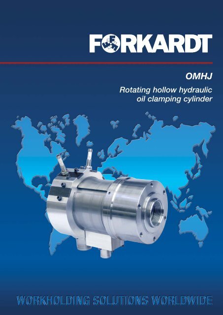
OMHJ<br />
Rotating hollow hydraulic<br />
oil clamping cylinder
H Y D R A U L I C O I L<br />
2<br />
General <strong>information</strong><br />
FORKARDT rotating hollow cylinders provide the<br />
axial force needed for your lathe's power chuck.<br />
The interaction between these two components<br />
is of crucial importance for the optimal production<br />
process. The system's oil circuit, including the<br />
hydraulic power unit, the attached hydraulic oil<br />
hoses, and the stationary supply housing, has<br />
been designed for the greatest precision with<br />
the OMHJ. The end stage is made up of the ring<br />
channels that supply the cylinder with the oil<br />
it needs.<br />
Gap seals and labyrinth glands serve to maintain<br />
the clamping pressure at a constant level, minimising<br />
friction losses.<br />
As precautionary measures against abrupt<br />
pressure drops controlled check valves are<br />
installed in both pressure lines.<br />
The key features at a glance<br />
• compact modular design<br />
• compact attachment to all lathes<br />
• perfected bearing and sealing technology<br />
• high precision oil supply system<br />
• wide 8–60 bar control range<br />
• pressure relief device<br />
• alternately actuated safety shutoff valves*)<br />
5<br />
3 4 8 1<br />
6<br />
7<br />
2<br />
You can therefore operate<br />
your lathe safely in<br />
the knowledge that our<br />
system can maintain the<br />
clamping pressure your<br />
lathe needs.<br />
The coolant used in<br />
machining operations<br />
is collected in a water<br />
catchment tray and<br />
drawn off through a<br />
separate circuit.<br />
OMHJ<br />
Hollow hydraulic oil<br />
clamping cylinder<br />
The limit switch fasteners are easy to configure<br />
and replace. Up to four matched limit switches<br />
can be used on the cylinder. These are available<br />
as optional accessories.<br />
• water catchment tray<br />
• clamping length end monitor as standard*)<br />
• optional continuous clamping length monitor<br />
• hydraulic oil connections on both sides<br />
• balanced as per ISO 1940<br />
• developed and manufactured as<br />
per ISO 9001<br />
*) compliance with the testing principles issued by the<br />
professional association<br />
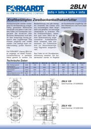
Structure of a hollow<br />
clamping mechanism:<br />
1) power chuck<br />
2) chuck flange<br />
3) OMHJ hollow clamping cylinder<br />
4) cylinder flange<br />
5) clamping length monitor<br />
6) mounting bolt<br />
7) tie bar<br />
8) machine spindle<br />
O M H J R O T A T I N G OMHJ ROTATING HYDRAULIC OIL CYLINDER<br />
423.10.01 E 3/10
423.10.01 E 3/10 C<br />
Y L I N D E R<br />
Notes<br />
An intermediate filter (≤ 15 µm) prevents<br />
malfunctions caused by contaminants in the oil.<br />
As a measure to lock the stationary oil supply<br />
housing in place a fork is provided at the connecting<br />
nozzles, but not at the leakage oil discharge<br />
nozzle! There must be no radial forces,<br />
so rigid piping must not be used!<br />
Technical features:<br />
hydraulic oil connections<br />
on both sides<br />
øC2<br />
E3<br />
L1<br />
J4<br />
G2<br />
H6<br />
G5<br />
M1<br />
M2<br />
G4<br />
H<br />
øB<br />
H3<br />
H4 H1<br />
Example order:<br />
øA<br />
øC1<br />
D<br />
H2<br />
H5 J1<br />
1 hollow hydraulic oil cylinder<br />
type OMHJ 128-55, (ID no. D168557000)<br />
1 set of FN 364 pressure hoses<br />
(ID no. D1075394000) 3,000 mm long<br />
1 length of leakage oil hose, 3,000 mm long<br />
(ID no. D1075547000)<br />
1 length of coolant hose, 3,000 mm long<br />
(ID no. D1075566000).<br />
5<br />
J<br />
J2<br />
G1<br />
G<br />
ø E1<br />
ø C<br />
ø L<br />
K max<br />
ø E<br />
The leakage oil and coolant discharges must<br />
exhibit a downward gradient over their whole<br />
lengths, and the leakage oil and coolant must<br />
be able to drain away without pressure<br />
(through a transparent hose).<br />
During continuous duty the supply temperature<br />
of the hydraulic oil should not exceed 60°C.<br />
Otherwise an oil cooler must be installed.<br />
OMHJ Hollow cylinder Type 108-42 128-55 160 180<br />
Max speed min -1 7,600 6,300 5,600 4,700<br />
Effective piston area A1 (cm2 ) 67 89.08 137.4 159.4<br />
Axial force Fax1 at 60 bar daN 4000 5300 8200 9500<br />
Effective piston area A2 (cm 2 ) 71.97 98.48 147.6 178,5<br />
Axial force Fax2 at 60 bar daN 4300 5900 8800 10700<br />
Displacement dm 3 0.18 0.25 0.78 1,13<br />
Moment of inertia J kgm 2 0.02 0.03 - - -<br />
Weight kg 21 22 39 49<br />
Leakage oil (at 30 bar and dm 3 /min 1.5 1.8 - -<br />
ISO VG46 oil temperature 50 °C)<br />
Dimensions<br />
- - - -<br />
Piston diameter A 108 128 160 180<br />
Bore B +0,2 42 54 72 88<br />
Chuck centring C j6 85 100 125 125<br />
Piston stroke<br />
Performance data<br />
D 25 25 30 30<br />
Tie bar centring Ø C1 47 62 77 97<br />
Centring Ø C2 H8 - 85 (H8) 105 121<br />
Outer diameter Ø E 144 164 200 215<br />
Tie bar outer diameter Ø E1 56 71 90 110<br />
Cover bore Ø E3 - 60 78 94<br />
Tie bar thread G M50 x 2 M62 x 2 M80 x 2 M100 x 2<br />
Fastening thread G1 6 x M8 6 x M8 6 x M10 6 x M10<br />
Thread G2 - M4 M4 M4<br />
Pressure connection thread<br />
(both sides)<br />
G3 R 1/4” R 1/4 ” R 3/8 ” R 3/8 ”<br />
O. D. leakage oil nozzle Ø G4 - 36 36 51<br />
Outer diameter<br />
cooling water nozzle<br />
Ø G5 - 45 45 45<br />
Total length H 266.2 267 298 334<br />
Inside calliper gauge H1 147 153 170 190<br />
Cylinder height H2 - 92.5 101.5 114<br />
Inside calliper gauge H3 159.5 163 179.5 211.5<br />
Inside calliper gauge H4 - 82 91 101<br />
Distance between pressure connectors H5 - 17 19 21<br />
Inside calliper gauge H6 34 34 39 39<br />
Piston pipe centring depth J 40 40 40 40<br />
Piston pipe thread depth Ø J1 30 30 30 30<br />
Fastening thread length Ø J2 - 16 18.5 18<br />
Max tie bar projection Kmax 12 12 16 16<br />
Pitch circle diameter Ø L ±0,2 124 140 180 195<br />
Pitch circle diameter Ø L1 58 71 91 107<br />
Inside calliper gauge<br />
Ident-No.<br />
M1 - 172 1055 124<br />
D168556000 D168557000 D171159000 D171160000<br />
In addition:<br />
1 set (= 2 pcs) of R 3/8" shear pin clutches<br />
1 set (= 2 pcs) of R 3/8" screw sockets<br />
3
BUSINESS<br />
PARTNER<br />
L O C A T I O N S W O R L D W I D E<br />
FORKARDT DEUTSCHLAND GMBH<br />
Heinrich-Hertz-Str. 7<br />
D-40699 Erkrath<br />
Tel: (+49) 211-25 06-0<br />
Fax: (+49) 211-25 06-221<br />
E-Mail: info@forkardt.com<br />
BUCK CHUCK<br />
2155 Traversefield Drive<br />
Traverse City, MI 49686, USA<br />
Tel: (+1) 800-228-2825<br />
(+1) 231-995-8312<br />
Fax: (+1) 231-995-8362<br />
E-Mail: sales@itwworkholding.com<br />
Website: www.buckchuckusa.com<br />
FORKARDT SCHWEIZ GmbH<br />
Industriestrasse 3<br />
CH-8307 Effretikon<br />
Tel: (+41) 52-3 553131<br />
Fax: (+41) 52-3 435240<br />
E-Mail: info-ch@forkardt.com<br />
ITW WORKHOLDING<br />
2155 Traversefield Drive<br />
Traverse City, MI 49686, USA<br />
Tel: (+1) 800-544-3823<br />
(+1) 231-947-5755<br />
Fax: (+1) 231-995-8361<br />
E-Mail: sales@itwworkholding.com<br />
Website: www.itwworkholding.com<br />
FORKARDT FRANCE S.A.R.L.<br />
28 Avenue de Bobigny<br />
F-93135 Noisy le Sec Cédex<br />
Tel: (+33) 1-4183 1240<br />
Fax: (+33) 1-4840 4759<br />
E-Mail: forkardt.france@forkardt.com<br />
FORKARDT NORTH AMERICA<br />
2155 Traversefield Drive<br />
Traverse City, MI 49686, USA<br />
Tel: (+1) 800-794-6190<br />
(+1) 231-947-5755<br />
Fax: (+1) 231-995-8361<br />
E-Mail: sales@itwworkholding.com<br />
Website: www.itwworkholding.com<br />
© 2010 FORKARDT, Errors and omissions excepted. ITW Workholding-Group is a division of Illinois Tool Works Inc.<br />
www.forkardt.com<br />
www.itwworkholding.com<br />
423.10.01 E 3/010-0.0 FK Printed in Germany