Body/equipment mounting directives FE New Zealand
Body/equipment mounting directives FE New Zealand
Body/equipment mounting directives FE New Zealand

Create successful ePaper yourself
Turn your PDF publications into a flip-book with our unique Google optimized e-Paper software.
Mitsubishi Fuso Service<br />
<strong>Body</strong>/<strong>equipment</strong> <strong>mounting</strong> <strong>directives</strong><br />
<strong>FE</strong><br />
<strong>New</strong> <strong>Zealand</strong><br />
KAWASAKI, JAPAN
Contents<br />
1 Introduction<br />
1.1 The aim of these <strong>directives</strong> 5<br />
1.2 Conventions 7<br />
1.3 Vehicle safety 8<br />
1.4 Operational reliability 9<br />
1.5 Accident prevention 10<br />
2 General<br />
2.1 Vehicle and model designations 11<br />
2.2 Technical advice and contact persons 13<br />
2.3 Required documents 14<br />
2.4 Product safety 15<br />
2.5 Mitsubishi three diamonds and<br />
Fuso emblem 17<br />
2.6 Recycling of components 18<br />
2.7 Quality system 19<br />
3 Planning of bodies<br />
3.1 Selecting the chassis 20<br />
3.2 Vehicle modifications 21<br />
3.3 Dimensions, weights, overall vehicle<br />
height 22<br />
3.4 About vehicle body incline 25<br />
3.5 Tyres 26<br />
3.6 Bolted and welded connections 27<br />
3.7 Soundproofing 29<br />
3.8 Duonic 30<br />
3.9 Exhaust system 36<br />
3.10 Maintenance and repairs 38<br />
3.11 Special <strong>equipment</strong> 41<br />
4 Technical threshold values for<br />
planning<br />
4.1 Vehicle overhang and technical<br />
wheelbases 42<br />
4.2 Weight distribution, CoG height,<br />
anti-roll bars 44<br />
4.3 Steerability 45<br />
4.4 Clearance for assemblies and cab 46<br />
4.5 Wind deflectors 48<br />
i<br />
4.6 Governor and transmission<br />
power-take-off 51<br />
5 Damage prevention<br />
5.1 Electrical system 62<br />
5.2 Brake hoses/cables and lines 70<br />
5.3 Mobile communications systems 71<br />
5.4 Electromagnetic compatibility (EMC) 72<br />
5.5 Welding work 73<br />
5.6 Corrosion protection measures 75<br />
5.7 Corrosion prevention in welding work 77<br />
5.8 Bolted connections 78<br />
5.9 Painting work 80<br />
5.10 Leaf springs 84<br />
5.11 Tilting the cab 85<br />
5.12 Towing and tow-starting 86<br />
5.13 Risk of fire 87<br />
5.14 Storing and handing over the vehicle 88<br />
6 Modifications to the basic vehicle<br />
6.1 General 89<br />
6.2 Chassis frame material 90<br />
6.3 Drilling work on the vehicle frame 91<br />
6.4 Welding work on the vehicle frame 93<br />
6.5 Reinforcement on side rail 94<br />
6.6 Brake systems 96<br />
6.7 Modifications to the wheelbase 97<br />
6.8 Frame modifications 98<br />
6.9 Mounting <strong>equipment</strong> on the side rail 101<br />
6.10 Cab 106<br />
6.11 Seats and bench seat 109<br />
6.12 Electrics/electronics 110<br />
6.13 Installation of propeller shafts 120<br />
7 Construction of bodies<br />
7.1 General 121<br />
7.2 Mounting frame 122<br />
7.3 Mounting frame attachment 126<br />
7.4 Clearance between chassis<br />
parts and bodies 128<br />
7.5 Fuel tank 131<br />
7.6 BlueTec ® system 133<br />
Mitsubishi Fuso body/<strong>equipment</strong> <strong>mounting</strong> <strong>directives</strong> for <strong>FE</strong> Issue date: 18. 04. 2011<br />
! Only print out complete sections from the current version<br />
2
Contents<br />
8 Calculations<br />
8.1 Axle load calculation 137<br />
9 Technical data<br />
9.1 Vehicle performance list 139<br />
9.2 Performance curve 140<br />
9.3 Weight distribution table 168<br />
9.4 Chassis cab drawings 201<br />
9.5 Frame layout 251<br />
9.6 Spring diagram 270<br />
9.7 Lamp layout drawings 290<br />
9.8 Power train 293<br />
9.9 Differential and tyre bound height 294<br />
9.10 Engine transmission assembly 296<br />
9.11 Transmission PTO assy 297<br />
9.12 Transmission power-take-off layout 298<br />
9.13 Battery <strong>mounting</strong> layout 299<br />
9.14 Fuel tank <strong>mounting</strong> layout 302<br />
9.15 BlueTec ® exhaust gas<br />
aftertreatment 311<br />
9.16 Labels and marks 315<br />
9.17 Electrical wiring diagram 319<br />
i<br />
Mitsubishi Fuso body/<strong>equipment</strong> <strong>mounting</strong> <strong>directives</strong> for <strong>FE</strong> Issue date: 18. 04. 2011<br />
! Only print out complete sections from the current version<br />
3
2General<br />
2.1 Vehicle and model designations<br />
2.1.1 Model coding system<br />
F E B 5 1<br />
i<br />
E R 4 S F<br />
2.1 Vehicle and model designations<br />
A C<br />
Engine model / Emission<br />
1 : 4P10 / EURO<br />
Front suspension system / GVW<br />
2 : Independent / GVW3.55 – 4.95t<br />
5 : Rigid / GVW5 – 6t<br />
7 : Rigid / GVW6.05 –7.5t<br />
9 : Rigid / GVW 7.5t over<br />
Wheel base<br />
C : (2800mm) ~ K : (4750mm)<br />
Steering position<br />
R : RHD<br />
Transmission / Deck height<br />
1 : AMT / Low deck<br />
2 : MT / Low deck<br />
3 : AMT / High deck<br />
4 : MT / High deck<br />
Cab style<br />
S : Single cab<br />
W : Crew cab<br />
Code Destination<br />
FA : Australia / <strong>New</strong> <strong>Zealand</strong><br />
Variation (e.g. engine power variants)<br />
B : 96kw<br />
C : 110kW<br />
D : 129kw<br />
Development sequential number / Cab type / Frame width<br />
A : Standard cab / Frame width : 700mm<br />
B : Wide cab / Frame width : 750mm<br />
C : Wide cab / Frame width : 850mm<br />
Vehicle category / Notification type / Drive system<br />
E : Standard category / Non-specification / 4x2<br />
Vehicle style<br />
F : Cab-over<br />
Mitsubishi Fuso body/<strong>equipment</strong> <strong>mounting</strong> <strong>directives</strong> for <strong>FE</strong> Issue date: 18. 04. 2011<br />
! Only print out complete sections from the current version<br />
11
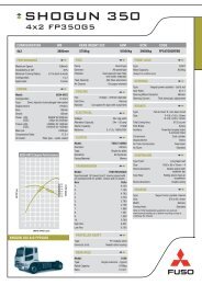
CANTER EURO 5 MODEL RANGE FOR NEW ZEALAND<br />
NOTE: NZ models GVW/GCW may differ from the specificationson on page 139 & 293 Jul‐11<br />
FUSO Code Order Code Model Group GVW GCW Front GVW Rear GVW W/base Power T/M CAB SUSP Tare weight KG<br />
<strong>FE</strong>A21CR3SFAC <strong>FE</strong>A45C2 2800 6 spd DUO NARROW CAB 1950<br />
<strong>FE</strong>A21ER3WFAC <strong>FE</strong>W45E2 3400 6 spd DUO NARROW D/CAB 2180<br />
<strong>FE</strong>B21CR4SFAC <strong>FE</strong>B45C1 2800 5 spd man 2045<br />
516 4.5T 8000 2300 3800<br />
110<br />
IFS<br />
<strong>FE</strong>B21CR3SFAC <strong>FE</strong>B45C2 2800 6 spd DUO 2065<br />
WIDE CAB<br />
<strong>FE</strong>B21ER4SFAC <strong>FE</strong>B45E1 3400 5 spd man 2070<br />
<strong>FE</strong>B21ER3SFAC <strong>FE</strong>B45E2 3400 6 spd DUO 2090<br />
<strong>FE</strong>A21CR3SFAC <strong>FE</strong>A50C2 2800 6 spd DUO NARROW CAB 1950<br />
<strong>FE</strong>A21ER3WFAC <strong>FE</strong>W50E2 3400 6 spd DUO NARROW D/CAB 2180<br />
<strong>FE</strong>B21CR4SFAC <strong>FE</strong>B50C1 2800 5 spd man 2045<br />
516 5.0T 8500 2300<br />
3800<br />
110<br />
IFS<br />
<strong>FE</strong>B21CR3SFAC <strong>FE</strong>B50C2 2800 6 spd DUO 2065<br />
WIDE CAB<br />
<strong>FE</strong>B21ER4SFAC <strong>FE</strong>B50E1 3400 5 spd man 2070<br />
<strong>FE</strong>B21ER3SFAC <strong>FE</strong>B50E2 3400 6 spd DUO 2090<br />
<strong>FE</strong>B51ER4SFAC <strong>FE</strong>B60E1 3400 5 spd man 2245<br />
<strong>FE</strong>B51ER3SFAC <strong>FE</strong>B60E2 3400 6 spd DUO 2270<br />
WIDE CAB<br />
<strong>FE</strong>B51GR4SFAC <strong>FE</strong>B60G1 616 6.0T 9000 2570 4500<br />
3850 110 5 spd man LEAF SPRING<br />
2265<br />
<strong>FE</strong>B51GR3SFAC <strong>FE</strong>B60G2 3850 6 spd DUO 2290<br />
<strong>FE</strong>B71ER3WFAC <strong>FE</strong>W60E2 3400 6 spd DUO WIDE D/CAB 2650<br />
<strong>FE</strong>B71GR4SFAC <strong>FE</strong>B75G1 3850 5 spd man 2425<br />
WIDE CAB<br />
<strong>FE</strong>B71GR3SFAC <strong>FE</strong>B75G2 816 7.5T 11000 3100<br />
6000 3850 110 6 spd DUO LEAF SPRING<br />
2445<br />
<strong>FE</strong>B71ER3WFAC <strong>FE</strong>W75E2 3400 6 spd DUO WIDE D/CAB 2650<br />
<strong>FE</strong>C91GR4SFAD <strong>FE</strong>C82G1 3850 5 spd man 2480<br />
<strong>FE</strong>C91GR3SFAD <strong>FE</strong>C82G2 3850 6 spd DUO 2495<br />
<strong>FE</strong>C91HR4SFAD <strong>FE</strong>C82H1 4300 5 spd man 2515<br />
WIDE CAB<br />
<strong>FE</strong>C91HR3SFAD <strong>FE</strong>C82H2 918 8.2T 11700 3100 6000<br />
4300 129<br />
6 spd DUO LEAF SPRING<br />
2530<br />
<strong>FE</strong>C91KR4SFAD <strong>FE</strong>C82K1 4750 5 spd man 2535<br />
<strong>FE</strong>C91KR3SFAD <strong>FE</strong>C82K2 4750 6 spd DUO 2550<br />
<strong>FE</strong>B91GR3WFAD <strong>FE</strong>W82G2 3850 6 spd DUO WIDE D/CAB 2715<br />
MODELS with passenger air bag and inspection hatch<br />
PAGE 11A
2 General<br />
2.1.2 Vehicle and model designation<br />
Engine Type<br />
Number of Cylinders<br />
Output<br />
Maximum torque<br />
i<br />
(kW)<br />
(rpm)<br />
(Nm)<br />
(rpm)<br />
2.1 Vehicle and model designations<br />
<strong>FE</strong>A2 <strong>FE</strong>A2 <strong>FE</strong>B2 <strong>FE</strong>B5<br />
4P10T2<br />
L4<br />
96<br />
3500<br />
300<br />
1300<br />
4P10T4<br />
L4<br />
110<br />
3500<br />
370<br />
1600<br />
4P10T4<br />
L4<br />
110<br />
3500<br />
370<br />
1600<br />
Mitsubishi Fuso body/<strong>equipment</strong> <strong>mounting</strong> <strong>directives</strong> for <strong>FE</strong> Issue date: 18. 04. 2011<br />
! Only print out complete sections from the current version<br />
4P10T4<br />
L4<br />
110<br />
3500<br />
370<br />
1600<br />
Cab Standard <br />
Wide <br />
Crew <br />
Transmission MT M038S5 - M038S5 M038S5<br />
AMT M038S6 M038S6 M038S6 M038S6<br />
Wheelbase (mm) 2800 <br />
3400 <br />
3850<br />
4300<br />
4750<br />
<br />
Permissible Gross Vehicle Weight<br />
Total 3510 4500 4500<br />
STD:6000/<br />
OPT:4500<br />
Permissible axle load<br />
Front 2300 2300 2300 2570<br />
and weight (kg) Rear 3800 3800 3800 4500<br />
Permissible total gross<br />
weight of combination<br />
(kg) 7000 8000 8000<br />
STD:9500/<br />
OPT:8000<br />
Engine Type<br />
Number of Cylinders<br />
Output<br />
Maximum torque<br />
(kW)<br />
(rpm)<br />
(Nm)<br />
(rpm)<br />
<strong>FE</strong>B7 <strong>FE</strong>C7 <strong>FE</strong>B9/<strong>FE</strong>C9<br />
4P10T4<br />
L4<br />
110<br />
3500<br />
370<br />
1600<br />
4P10T4<br />
L4<br />
110<br />
3500<br />
370<br />
1600<br />
4P10T6<br />
L4<br />
129<br />
3500<br />
430<br />
1600<br />
Cab Standard<br />
Wide <br />
Crew <br />
Transmission MT M038S5 M038S5 M038S5<br />
AMT M038S6 M038S6 M038S6<br />
Wheelbase (mm) 2800 <br />
3400 <br />
3850 <br />
4300 <br />
4750 <br />
Permissible Gross Vehicle Weight<br />
Permissible axle load<br />
and weight (kg)<br />
Permissible total gross<br />
weight of combination<br />
(kg)<br />
Total<br />
STD:7500/<br />
OPT:4500<br />
STD:7500/<br />
OPT:4500<br />
8200<br />
Front 3100 3100 3100<br />
Rear 6000 6000 6000<br />
STD:11000/<br />
OPT:8000<br />
STD:11000/<br />
OPT:8000<br />
11700<br />
12
5 Damage prevention<br />
Between battery terminal and fuse<br />
i<br />
Addition on the<br />
built body<br />
Terminal for taking power<br />
on built body side,<br />
M8 screw<br />
Additional fuse,<br />
etc.<br />
5.1 Electrical system<br />
(f) Use a round flat terminal for the power supply terminal and jointly fasten it by using the fixing nut for<br />
attaching the battery cable terminal.<br />
Only one power supply terminal may be used.<br />
Two or more additional terminals can be loosened, resulting in heat being generated or a short.<br />
List of recommended combinations of fuse capacity and wire size<br />
Note: Keep the continuous permissible current within 70 % of the fuse specifications value.<br />
(E.g.) If the fuse used is 10 A:<br />
10 × 0.7=7(A)<br />
A load of up to 7 A can be used.<br />
Notes:<br />
1. : Not usable; — : 50 m max<br />
2. AV/AVS wires: general wires; AVX wires: heat-resistant wires<br />
Ground point<br />
Battery cable (-)<br />
Battery cable (+)<br />
: Usable : Not usable<br />
Fuse Wire size (mm 2 ) [upper] and wire permissible current (A) [lower]<br />
Type Specifications<br />
Blade and<br />
glass tube<br />
0.3 0.5 0.85 1.25 2.0 3.0 5.0 (mm 2 )<br />
11 14 18 23 31 42 57 (A)<br />
5A <br />
7.5 A <br />
10 A <br />
15 A <br />
Mitsubishi Fuso body/<strong>equipment</strong> <strong>mounting</strong> <strong>directives</strong> for <strong>FE</strong> Issue date: 18. 04. 2011<br />
! Only print out complete sections from the current version<br />
68
5 Damage prevention<br />
5.1.5 Batteries<br />
• Never place any metal objects or tools on the<br />
batteries.<br />
• There is a risk of short circuit if the positive<br />
terminal clamp on the connected battery comes<br />
into contact with vehicle parts. This could cause<br />
the highly explosive gas mixture to ignite. You and<br />
others could be seriously injured as a result.<br />
• When disconnecting the batteries, always<br />
disconnect the negative terminal clamp first and<br />
then the positive terminal.<br />
• When connecting the batteries, always connect the<br />
positive terminal clamp first and then the negative<br />
terminal.<br />
• Incorrect polarity of the supply voltage can cause<br />
irreparable damage to the control units.<br />
• Never start the engine without a connected battery<br />
(battery terminals tightened).<br />
• Do not disconnect or remove the battery terminals<br />
while the engine is running.<br />
• If the batteries are flat, the engine can be jumpstarted<br />
using jump leads connected to the batteries<br />
of another vehicle. Observe the Instruction Manual.<br />
Do not use a quick charger for jump-starting.<br />
• Only tow-start the vehicle with the batteries<br />
connected.<br />
• Quick-charge the batteries only after<br />
disconnecting them from the vehicle's electrical<br />
system. Both the positive and negative terminals<br />
must be disconnected.<br />
i<br />
Installing additional electrical consumers<br />
page 110.<br />
i<br />
5.1 Electrical system<br />
5.1.6 Lines, plug connections and control units<br />
• A plug connection must not be unplugged from or<br />
plugged into the control units while the ignition is<br />
on.<br />
• Lines must be protected from heat by means of<br />
insulation.<br />
• Route cables in such a way that chafing cannot<br />
occur, particularly at crossover points and sharp<br />
edges. If necessary, use cable ducts or guide pipes.<br />
• Do not carry out tests at connector terminals using<br />
unsuitable tools (test probes, wire ends, etc.). This<br />
may lead to contact damage and subsequent<br />
problems. Use suitable test leads.<br />
• The department responsible must be consulted if a<br />
battery isolating switch is to be retrofitted<br />
page 13.<br />
Mitsubishi Fuso body/<strong>equipment</strong> <strong>mounting</strong> <strong>directives</strong> for <strong>FE</strong> Issue date: 18. 04. 2011<br />
! Only print out complete sections from the current version<br />
69
5 Damage prevention<br />
5.2 Brake hoses/cables and lines<br />
a Risk of accident<br />
Work carried out incorrectly on the brake hoses,<br />
cables and lines may impair their function. This may<br />
lead to the failure of components or parts relevant<br />
to safety.<br />
• Fuel and hydraulic lines and brake hoses must be<br />
covered or removed if necessary before carrying<br />
out any welding, drilling and grinding work and<br />
before working with cutting discs.<br />
• After installing, fuel lines, hydraulic lines and brake<br />
hoses, the system must be tested for pressure loss<br />
and leaks.<br />
• No other lines may be attached to brake hoses.<br />
• Lines must be protected from heat by means of<br />
appropriate insulation.<br />
• Line routing must be designed to prevent any<br />
increase in pressure loss.<br />
Comply with all national regulations and laws.<br />
i<br />
5.2 Brake hoses/cables and lines<br />
Mitsubishi Fuso body/<strong>equipment</strong> <strong>mounting</strong> <strong>directives</strong> for <strong>FE</strong> Issue date: 18. 04. 2011<br />
! Only print out complete sections from the current version<br />
70
5 Damage prevention<br />
5.3 Mobile communications systems<br />
The ADR/GGVS regulations (Hazardous Materials<br />
Road Transport Regulations and European Agreement<br />
concerning the International Carriage of Dangerous<br />
Goods by Road) and the manufacturer's information<br />
and installation specification must be observed.<br />
If mobile communication systems (e.g. telephone,<br />
CB radio) are retrofitted, the following requirements<br />
must be fulfilled in order to avoid malfunctions<br />
developing on the vehicle at a later stage.<br />
Equipment<br />
• The <strong>equipment</strong> must have official approval and<br />
correspond to DIN VDE 0879, Part 2.<br />
• The <strong>equipment</strong> must be permanently installed.<br />
• Operation of portable or mobile <strong>equipment</strong> inside<br />
the cab is only permitted if this <strong>equipment</strong> is<br />
connected to a permanently installed external<br />
aerial.<br />
• The transmitter must be installed separately from<br />
all other vehicle electronics.<br />
• Protect <strong>equipment</strong> from moisture.<br />
• Observe the permissible operating temperature.<br />
• Protect the <strong>equipment</strong> against severe mechanical<br />
vibrations.<br />
Aerial (for two-way radio sets)<br />
• The aerial must be officially licensed.<br />
i<br />
5.3 Mobile communications systems<br />
Connection and wiring<br />
• The connection should be made directly to<br />
teriminal inside cab page 113.<br />
• Disconnect the unit from the electrical system<br />
before jump-starting.<br />
• Cables should be wired via the shortest possible<br />
route (not looped) and twisted.<br />
• Ensure that the system has a good earth<br />
connection to the body (aerial and <strong>equipment</strong>).<br />
• The aerial and connecting cables between the<br />
transmitter, receiver and control panel must be<br />
routed separately from the vehicle wiring harness<br />
in the vicinity of the body earth.<br />
• Make sure that the aerial cable is not kinked or<br />
crushed.<br />
i<br />
The notes on operating safety and vehicle safety in<br />
Section 1 "Introduction" page 8 and page 9<br />
must be complied with.<br />
Mitsubishi Fuso body/<strong>equipment</strong> <strong>mounting</strong> <strong>directives</strong> for <strong>FE</strong> Issue date: 18. 04. 2011<br />
! Only print out complete sections from the current version<br />
71
5 Damage prevention<br />
5.4 Electromagnetic compatibility (EMC)<br />
The different electrical consumers on board the<br />
vehicle cause electrical interference in the vehicle's<br />
electrical circuit. At Mitsubishi Fuso, electronic<br />
components installed at the factory are checked for<br />
their electromagnetic compatibility in the vehicle.<br />
When retrofitting electric or electronic systems, they<br />
must be tested for electromagnetic compatibility and<br />
this must be documented.<br />
The <strong>equipment</strong> must have been granted type approval<br />
in accordance with EC Directive 95/54/EEC and must<br />
bear the "e" mark.<br />
The following standards provide information on this:<br />
• DIN 40839<br />
• DIN 57879, Part 3<br />
• VDE 0879, Part 3<br />
• DC 10614 (EMC component requirements)<br />
• DC 10613 (EMC vehicle requirements)<br />
• EU Directive 95/54/EEC<br />
i<br />
The notes on operating safety and vehicle safety in<br />
Section 1 "Introduction" page 8 and page 9<br />
must be complied with.<br />
i<br />
5.4 Electromagnetic compatibility (EMC)<br />
Mitsubishi Fuso body/<strong>equipment</strong> <strong>mounting</strong> <strong>directives</strong> for <strong>FE</strong> Issue date: 18. 04. 2011<br />
! Only print out complete sections from the current version<br />
72
5 Damage prevention<br />
5.5 Welding work<br />
a Risk of injury<br />
Welding work in the vicinity of the airbags can<br />
cause the restraint system to malfunction.<br />
Welding work near the airbags is strictly forbidden.<br />
The airbag could be triggered or may no longer<br />
function correctly.<br />
The legal stipulations regarding the transport and<br />
storage of airbag units must be observed.<br />
All laws governing explosive substances must be<br />
complied with.<br />
The following safety measures must be observed to<br />
prevent damage to components caused by<br />
overvoltage during welding work:<br />
• Disconnect the positive and negative terminals<br />
from the battery and cover them.<br />
• Connect the welding-unit earth terminal directly to<br />
the part to be welded.<br />
• Do not touch electronic component housings<br />
(e.g. control modules) and electric lines with the<br />
welding electrode or the earth contact clamp of the<br />
welding unit.<br />
• Before welding, cover spring to protect them from<br />
welding spatter. Do not touch springs with welding<br />
electrodes or welding tongs.<br />
• Cover the fuel tank and fuel system (lines, etc.)<br />
before carrying out welding work.<br />
• Avoid welding work on inaccessible cavities in the<br />
cab.<br />
• Welds must be ground down and reinforced with<br />
angular profiles to prevent notching from welding<br />
penetration.<br />
• Avoid welds in bends.<br />
• The distance from a weld to the outer edge should<br />
always be at least 15 mm.<br />
i<br />
!<br />
5.5 Welding work<br />
Do not connect the arc welder earth clamp to<br />
assemblies such as the engine, gearbox or axles.<br />
Welding work is not permitted on assemblies such<br />
as the engine, gearbox, axles, etc.<br />
• Avoid defects such as deposited metal cracking,<br />
toe crack, blow holes, slag inclusion, under cut,<br />
poor penetration, etc.<br />
Mitsubishi Fuso body/<strong>equipment</strong> <strong>mounting</strong> <strong>directives</strong> for <strong>FE</strong> Issue date: 18. 04. 2011<br />
! Only print out complete sections from the current version<br />
73
5 Damage prevention<br />
i<br />
1<br />
4<br />
1 Deposited metal cracking<br />
2 Toe crack<br />
3 Blow hole<br />
The following safety measures must be observed to<br />
prevent damage to welding parts;<br />
• Do not weld any item to the frame to hold it<br />
temporarily.<br />
• Clean parts thoroughly with a wire brush and dry<br />
them off before welding.<br />
• Make sure the paint is completely removed, before<br />
welding a painted part.<br />
• Use a low hydrogen type welding electrode. The<br />
welding electrode absorbs moisture when it is<br />
used, so it is necessary to dry it thoroughly before<br />
use.<br />
• When welding, maintain the optimum welding<br />
speed and conditions for the preservation of the<br />
welding electrode.<br />
• Maintain the welding current at the optimum value<br />
for safety.<br />
• Make several short welding beads rather than one<br />
long bead.<br />
• Make symmetrical beads to limit shrinkage.<br />
• Avoid more than 3 welds at any one point.<br />
• Avoid welding in strain hardened zones.<br />
• When connecting the ground cable of the arc<br />
welder, make sure to disconnect the negative<br />
terminal from the battery. The ground of the<br />
welder should be connected to the side rail near<br />
the welded part. Never connect around the engine,<br />
transmission, propeller shaft, front and rear axles,<br />
etc.<br />
2<br />
5<br />
Fig. 1<br />
4 Slag inclusion<br />
5 Under cut<br />
6 Poor penetration<br />
5.5 Welding work<br />
• When performing welding work on the chassis,<br />
take proper measure to prevent the tubes,<br />
harnesses, rubber parts, springs, etc. from heat or<br />
spatter.<br />
• Do not cool parts off with water after welding.<br />
a Risk of accident and injury<br />
Before performing electric of arc welding as part of<br />
vehicle repair operation, disconnect the negative (-)<br />
cable from the battery. The earth cable of the<br />
welding machine should be connected to a point as<br />
close to the welding area as possible.<br />
Mitsubishi Fuso body/<strong>equipment</strong> <strong>mounting</strong> <strong>directives</strong> for <strong>FE</strong> Issue date: 18. 04. 2011<br />
! Only print out complete sections from the current version<br />
3<br />
6<br />
74
5 Damage prevention<br />
5.6 Corrosion protection measures<br />
General<br />
In order to preserve the durability and quality standard<br />
of the vehicle, measures must be taken to protect it<br />
against corrosion when the vehicle is modified and<br />
after installing bodies and fittings.<br />
Information on the design, execution of work and the<br />
requirements of the materials and components to be<br />
used with regard to corrosion protection is listed<br />
below.<br />
To achieve good corrosion protection, the areas of<br />
design (1), production (2) and materials (3) must be<br />
perfectly matched.<br />
Optimum corrosion protection<br />
i<br />
5.6 Corrosion protection measures<br />
Materials<br />
Corrosion<br />
protection<br />
Design Production<br />
Mitsubishi Fuso body/<strong>equipment</strong> <strong>mounting</strong> <strong>directives</strong> for <strong>FE</strong> Issue date: 18. 04. 2011<br />
! Only print out complete sections from the current version<br />
75
5 Damage prevention<br />
Disassembly of components<br />
If the body manufacturer makes structural<br />
modifications to the chassis, the corrosion protection<br />
in the affected areas must be restored to match the<br />
production standards of Mitsubishi Fuso. The areas<br />
must also be finished with appropriate paintwork.<br />
Information on approved Mitsubishi Fuso refinishing<br />
paint suppliers is available on request from the<br />
responsible department page 13.<br />
Damage to components<br />
If components are damaged during disassembly<br />
(scratches, scuff marks), they must be professionally<br />
repaired. This applies especially for drilled holes and<br />
openings. Two-component epoxy primers are<br />
particularly suitable for repair work.<br />
i<br />
5.6 Corrosion protection measures<br />
Cutting of components<br />
When cutting and grinding work is carried out, the<br />
adjacent painted components must be protected<br />
against flying sparks and shavings. Grinding dust and<br />
shavings must be carefully removed because these<br />
contaminants can spread corrosion. Edges and drilled<br />
holes must be cleanly deburred in order to guarantee<br />
optimum corrosion protection.<br />
Corrosion protection on reinforcements and<br />
fittings<br />
Reinforcements and fittings must receive adequate<br />
anti-corrosion priming prior to installation. In addition<br />
to galvanising, cataphoretic dip-priming and zinc-rich<br />
paint in sufficient coatings have proved satisfactory<br />
for this purpose.<br />
Mitsubishi Fuso body/<strong>equipment</strong> <strong>mounting</strong> <strong>directives</strong> for <strong>FE</strong> Issue date: 18. 04. 2011<br />
! Only print out complete sections from the current version<br />
76
5 Damage prevention<br />
5.7 Corrosion prevention in welding work<br />
In order to avoid crevice corrosion at weld seams, the<br />
welds should be made in accordance with the<br />
examples shown.<br />
Preparation<br />
The welding area must be free from corrosion, grease,<br />
dirt or similar contamination. If painted surfaces are to<br />
be welded, the paint coat must first be removed by<br />
grinding or chemical stripping. If this is not done, the<br />
paint will burn and the residues can impair corrosion<br />
resistance.<br />
After welding work<br />
• Remove drilling shavings.<br />
• Deburr sharp edges.<br />
• Remove any burned paint and thoroughly prepare<br />
surfaces for painting.<br />
• Prime and paint all unprotected parts.<br />
• Preserve cavities with wax preservative.<br />
• Carry out corrosion protection measures on the<br />
underbody and frame parts.<br />
i<br />
Plug and slot welds, particularly on horizontal<br />
surfaces, should be avoided due to the risk of corrosion.<br />
If they are unavoidable, these welds must<br />
receive additional preservation. Furthermore, avoid<br />
designs which allow moisture to accumulate. These<br />
must be fitted with additional drainage holes or<br />
gaps in the weld seam.<br />
i<br />
5.7 Corrosion prevention in welding work<br />
A B<br />
Example: Weld seams<br />
A – Suitable<br />
B – Unsuitable<br />
Mitsubishi Fuso body/<strong>equipment</strong> <strong>mounting</strong> <strong>directives</strong> for <strong>FE</strong> Issue date: 18. 04. 2011<br />
! Only print out complete sections from the current version<br />
77
5 Damage prevention<br />
5.8 Bolted connections<br />
Finish-painted components<br />
If painted parts are to be bolted together, the coats of<br />
paint must not cause settling in the bolted<br />
connections. In such cases, hard, high-density<br />
coatings such as cataphoretic immersion primers or<br />
powder coatings should be used. The coat thicknesses<br />
should be kept as small as possible (cataphoretic<br />
immersion primer approx. 20 µm, powder coatings<br />
approx. 100 µm).<br />
• If using bolts with serrations under the head, an<br />
additional top coat must be applied to touch up any<br />
paint damage.<br />
• The use of hexagon socket or Torx socket bolts in<br />
a horizontal position is to be avoided, as moisture<br />
can accumulate in the bolt head under certain<br />
conditions, leading to corrosion.<br />
Fasteners<br />
In areas susceptible to corrosion always use bolts,<br />
nuts, etc. with corrosion resistance (>480 h saline fog<br />
test according to ISO 9227) regardless of the required<br />
strength class. This standard is satisfied, e.g. by bolts<br />
with electroplating and additional thick-coat sealing<br />
and zinc platelet coatings with sealer (e.g. Dacromet<br />
or Deltaseal), refer to VDA 235-104 recommendation.<br />
Information on identifying suitable coatings can be<br />
obtained from your local bolt supplier.<br />
For details on bolted connections see Section 3<br />
page 27.<br />
i<br />
5.8 Bolted connections<br />
Mitsubishi Fuso body/<strong>equipment</strong> <strong>mounting</strong> <strong>directives</strong> for <strong>FE</strong> Issue date: 18. 04. 2011<br />
! Only print out complete sections from the current version<br />
78
5 Damage prevention<br />
Preventing contact corrosion<br />
Direct contact between materials with different<br />
electrode potentials can lead to corrosion of the less<br />
noble material when exposed to moisture and salt<br />
ions.<br />
When selecting materials, avoid the following<br />
combinations:<br />
• Chrome/nickel-steel with aluminium<br />
• Chrome/nickel-steel with zinc-coated steel<br />
Insulation by coating<br />
Contact corrosion can be prevented by using<br />
insulation such as washers, sleeves or bushings. Even<br />
in this case, however, the connecting points must not<br />
be persistently exposed to moisture.<br />
Vehicle cleaning and care<br />
When the vehicle is handed over to the body<br />
manufacturer, it must immediately be cleaned of salt<br />
and dirt. If it is to be stored for some time, the vehicle<br />
must be preserved.<br />
During modification it must be ensured that loadbearing<br />
components are additionally protected<br />
against aggressive chemicals and environmental<br />
influences. If the vehicle comes into contact with<br />
chemicals or salts (e.g. snow-clearing operations), it<br />
must be cleaned thoroughly at regular intervals.<br />
i<br />
5.8 Bolted connections<br />
Mitsubishi Fuso body/<strong>equipment</strong> <strong>mounting</strong> <strong>directives</strong> for <strong>FE</strong> Issue date: 18. 04. 2011<br />
! Only print out complete sections from the current version<br />
1<br />
2<br />
1 Insulating washer<br />
2 Insulating sleeve<br />
!<br />
A conductive connection occurs if two different<br />
metals are brought into contact with each other<br />
through an electrolyte (e.g. air humidity). This<br />
causes electrochemical corrosion and the less base<br />
of the two metals is damaged. The further apart the<br />
two metals are in the electrochemical potential<br />
series, the more intense electrochemical corrosion<br />
becomes.<br />
For this reason, electrochemical corrosion must be<br />
prevented by insulation or by treating the components<br />
accordingly, or it can be minimised by selecting<br />
suitable materials.<br />
2<br />
1<br />
79
5 Damage prevention<br />
5.9 Painting work<br />
H Environmental note<br />
Paints and lacquers are harmful to health and to the<br />
environment if they are not handled correctly.<br />
Dispose of paints and lacquers in an<br />
environmentally responsible manner.<br />
Paint compatibility should be checked when<br />
repainting. In order to avoid colour variations on<br />
painted bodies, Mitsubishi Fuso recommends that<br />
paints be used only if they have been tested and<br />
approved for the vehicle model in question.<br />
Information on the primers used at the factory and on<br />
Mitsubishi Fuso colour numbers can be obtained from<br />
the relevant department page 13.<br />
Mask the following areas before painting:<br />
• Sealing surfaces<br />
• Windows<br />
• Contact areas between the wheels<br />
and wheel hubs<br />
• Contact areas for wheel nuts<br />
• Breathers on gearboxes, axles, etc.<br />
• Disk brakes and disk rotors<br />
• Door locks<br />
• Door retainers in the rear door hinges<br />
• Coupling flanges of drive shafts and power takeoffs<br />
• Spring <strong>mounting</strong> area<br />
• Rubber hoses<br />
• Electric control unit TCU (Transmission Control<br />
Unit)<br />
i<br />
5.9 Painting work<br />
Mitsubishi Fuso body/<strong>equipment</strong> <strong>mounting</strong> <strong>directives</strong> for <strong>FE</strong> Issue date: 18. 04. 2011<br />
! Only print out complete sections from the current version<br />
80
5 Damage prevention<br />
5.9.1 Repainting of the cab<br />
• When a standard-colour-coated cab is repainted,<br />
plastic and rubber parts on it should be removed<br />
where possible to protect them from adverse<br />
effects.<br />
•Emblems<br />
•Front grille *1<br />
•Corner panels *1<br />
•Front cover<br />
•Steps<br />
•Fenders<br />
•Wipers<br />
•Antenna<br />
•Lamps<br />
•Outside mirrors, mirror stays<br />
•Bumper corner covers<br />
•Heat protector (at back of cab)<br />
•Sealing washers for screws<br />
i<br />
Removable parts Parts to be masked<br />
•Door outer handles<br />
•Weatherstrips *2<br />
•Caution labels<br />
•Door delta garnish<br />
•Door runchannels<br />
•Door sash garnish<br />
•Door beltline moldings<br />
5.9 Painting work<br />
*1 The caps covering the holes in the cab for <strong>mounting</strong> the radiator grille and corner panels cannot be reused<br />
once removed. Replace them with new ones.<br />
Part name Part No.<br />
Clip MK676916 (Mitsubishi Fuso part number)<br />
*2 Before reinstalling removed door weatherstrips, check their plastic clips for deformation in claws and defects<br />
preventing smooth insertion. Any defective clips must be replaced with new ones.<br />
Part name Part No.<br />
Clip MK402586 (Mitsubishi Fuso part number)<br />
Mitsubishi Fuso body/<strong>equipment</strong> <strong>mounting</strong> <strong>directives</strong> for <strong>FE</strong> Issue date: 18. 04. 2011<br />
! Only print out complete sections from the current version<br />
81
5 Damage prevention<br />
i<br />
5.9 Painting work<br />
Parts to be removed or shielded from heat when repainting at temperatures exceeding 80°C<br />
• Do not leave any plastic parts mounted on the cab<br />
during the painting, baking and drying processes.<br />
They must be removed prior to painting.<br />
Note 1. Acrylic lacquer type paint may be prone to<br />
blistering. For details, ask the paint<br />
manufacturer/supplier.<br />
Note 2. Be sure to sand the surfaces before<br />
repainting, otherwise the paint film may not<br />
adhere well.<br />
• Parts that must not be repainted<br />
The following parts are made of polypropylene<br />
(PP). Do not repaint them.<br />
•Weatherstrips<br />
•Rear view mirror bodies<br />
•Mud guard aprons<br />
•Washer nozzles<br />
•Splash aprons<br />
•Mud guards<br />
•Steps<br />
•Fenders<br />
•Runchannels<br />
•Bumper corner covers<br />
•Packing rubbers (mirror fitting, antenna fitting,<br />
and glip fitting bases)<br />
•Antenna<br />
The following parts should not be repainted for<br />
appearance reasons.<br />
•Emblems (such as FUSO)<br />
•Rear view mirror stays<br />
•Fenders<br />
•Wiper arms and blades<br />
•Antenna and its bracket<br />
Mitsubishi Fuso body/<strong>equipment</strong> <strong>mounting</strong> <strong>directives</strong> for <strong>FE</strong> Issue date: 18. 04. 2011<br />
! Only print out complete sections from the current version<br />
82
5 Damage prevention<br />
5.9.2 Laminated glass<br />
• When a repainted cab body is forced-dried, the<br />
temperature should not exceed 100 °C {212 °F}<br />
and the process must be completed within 60<br />
minutes. When using a temperature above 100 °C<br />
{212 °F}, cover the glass surfaces with shields to<br />
prevent them from being heated beyond 100 °C<br />
{212 °F} or remove the glass.<br />
• Laminated glass is marked by a double slash (//) in<br />
the lower left corner.<br />
i<br />
5.9 Painting work<br />
Mitsubishi Fuso body/<strong>equipment</strong> <strong>mounting</strong> <strong>directives</strong> for <strong>FE</strong> Issue date: 18. 04. 2011<br />
! Only print out complete sections from the current version<br />
83
5 Damage prevention<br />
5.10 Leaf springs<br />
• Only use spring leaves which have been tested and<br />
approved for the vehicle model in question.<br />
Reinforcement by installing additional spring<br />
leaves is not permitted.<br />
• Do not damage the surface or the corrosion<br />
protection of the spring leaves when carrying out<br />
installation work.<br />
• Before carrying out welding work, cover the spring<br />
leaves to protect them against welding spatter. Do<br />
not touch springs with welding electrodes or<br />
welding tongs.<br />
i<br />
5.10 Leaf springs<br />
Mitsubishi Fuso body/<strong>equipment</strong> <strong>mounting</strong> <strong>directives</strong> for <strong>FE</strong> Issue date: 18. 04. 2011<br />
! Only print out complete sections from the current version<br />
84
5 Damage prevention<br />
5.11 Tilting the cab<br />
a Risk of injury<br />
Before tilting the cab, please make sure that you<br />
read the "Tilting the cab" section in the detailed<br />
Instruction Manual.<br />
You could otherwise fail to recognise dangers,<br />
which could result in injury to yourself or others.<br />
i<br />
5.11 Tilting the cab<br />
Mitsubishi Fuso body/<strong>equipment</strong> <strong>mounting</strong> <strong>directives</strong> for <strong>FE</strong> Issue date: 18. 04. 2011<br />
! Only print out complete sections from the current version<br />
85
5 Damage prevention<br />
5.12 Towing and tow-starting<br />
a Risk of accident and injury<br />
Before towing or tow-starting, please make sure<br />
that you read the "Towing" section in the detailed<br />
Instruction Manual. You could otherwise fail to<br />
recognise dangers and cause an accident, which<br />
could result in injury to yourself or others.<br />
!<br />
Failure to observe the instructions in the Instruction<br />
Manual can result in damage to the vehicle.<br />
i<br />
5.12 Towing and tow-starting<br />
Mitsubishi Fuso body/<strong>equipment</strong> <strong>mounting</strong> <strong>directives</strong> for <strong>FE</strong> Issue date: 18. 04. 2011<br />
! Only print out complete sections from the current version<br />
86
5 Damage prevention<br />
5.13 Risk of fire<br />
a Risk of fire<br />
Work on live electrical lines carries a risk of short<br />
circuit.<br />
Before starting work on the electrical system,<br />
disconnect the on-board electrical system from the<br />
power source, e.g. battery.<br />
With all bodies make sure that neither flammable<br />
objects nor flammable liquids can come into<br />
contact with hot assemblies (including through<br />
leakages in the hydraulic system) such as the<br />
engine, gearbox, exhaust system, turbocharger, etc.<br />
Appropriate caps, seals and covers must be<br />
installed on the body in order to avoid the risk of<br />
fire.<br />
i<br />
5.13 Risk of fire<br />
Mitsubishi Fuso body/<strong>equipment</strong> <strong>mounting</strong> <strong>directives</strong> for <strong>FE</strong> Issue date: 18. 04. 2011<br />
! Only print out complete sections from the current version<br />
87
5 Damage prevention<br />
5.14 Storing and handing over the vehicle<br />
Storage<br />
To prevent any damage while vehicles are in storage,<br />
Mitsubishi Fuso recommends that they be serviced<br />
and stored in accordance with the manufacturer's<br />
specifications page 39.<br />
Handover<br />
To prevent damage to the vehicle or to repair any<br />
existing damage, Mitsubishi Fuso recommends that<br />
the vehicle be subjected to a full function check and a<br />
complete visual inspection before it is handed over<br />
page 40.<br />
i<br />
5.14 Storing and handing over the vehicle<br />
Mitsubishi Fuso body/<strong>equipment</strong> <strong>mounting</strong> <strong>directives</strong> for <strong>FE</strong> Issue date: 18. 04. 2011<br />
! Only print out complete sections from the current version<br />
88
6 Modifications to the basic vehicle<br />
6.1 General<br />
a Risk of injury<br />
Do not modify any bolted connections that are relevant<br />
to safety, e.g. that are required for wheel alignment,<br />
steering or braking functions.<br />
When unfastening bolted connections make sure<br />
that, when work is complete, the connection again<br />
corresponds with the original condition.<br />
Welding work on the chassis/body may only be<br />
carried out by trained personnel.<br />
The body, the attached or installed <strong>equipment</strong> and<br />
any modifications must comply with the applicable<br />
laws and <strong>directives</strong> as well as work safety or accident<br />
prevention regulations, safety rules and accident<br />
insurer leaflets.<br />
i<br />
i<br />
Mitsubishi Fuso body/<strong>equipment</strong> <strong>mounting</strong> <strong>directives</strong> for <strong>FE</strong> Issue date: 18. 04. 2011<br />
! Only print out complete sections from the current version<br />
6.1 General<br />
Further information on bolted and welded<br />
connections can be found in Section 3 "Planning of<br />
bodies" page 27 and Section 5 "Damage<br />
prevention" page 62.<br />
89
6 Modifications to the basic vehicle<br />
6.2 Chassis frame material<br />
If the frame is extend, the material of the extension<br />
element and reinforcing bracket must have the same<br />
quality and dimensions as the standard chassis frame.<br />
See the respective tender drawings for the<br />
longitudinal frame member dimensions.<br />
Material: <strong>FE</strong>A, <strong>FE</strong>B (except <strong>FE</strong>B2) MJSH440 or<br />
SAPH440 (JIS)<br />
(SAE J410950X or<br />
the equivalent)<br />
i<br />
<strong>FE</strong>B2, <strong>FE</strong>C . . . . . . . . . . HTP540<br />
6.2 Chassis frame material<br />
Mitsubishi Fuso body/<strong>equipment</strong> <strong>mounting</strong> <strong>directives</strong> for <strong>FE</strong> Issue date: 18. 04. 2011<br />
! Only print out complete sections from the current version<br />
90
6 Modifications to the basic vehicle<br />
6.3 Drilling work on the vehicle frame<br />
Drilling holes in side rail<br />
Holes have been drilled in the side rail at regular<br />
intervals (longitudinal pitch 50 mm, vertical pitch 40<br />
mm). Use the existing holes. Never drill holes in the<br />
upper and lower surfaces of the flange.<br />
As a rule, no holes may be enlarged. If it is absolutely<br />
necessary to enlarge one, keep its diameter within<br />
φ13.<br />
No load may be applied to the centre of the web of the<br />
longitudinal member (diaphragm effect). If this is<br />
unavoidable, make sure that there is a large area of<br />
support on both sides of the web.<br />
i<br />
6.3 Drilling work on the vehicle frame<br />
Mitsubishi Fuso body/<strong>equipment</strong> <strong>mounting</strong> <strong>directives</strong> for <strong>FE</strong> Issue date: 18. 04. 2011<br />
! Only print out complete sections from the current version<br />
91
6 Modifications to the basic vehicle<br />
Drilling work on the crossmembers<br />
• The holes and distances between the holes should<br />
conform to the values specified in the chart below.<br />
Crossmember type Hole<br />
diameter<br />
• Alligator type<br />
(see Fig. 1)<br />
• Channel type<br />
(see Fig. 2)<br />
Note*: Maintain the dimensions of previously drilled<br />
holes.<br />
1 100 mm min<br />
2 DIA 9 mm max<br />
3 25 mm min<br />
i<br />
9 mm<br />
max.<br />
Alligator type<br />
1<br />
Fig. 1<br />
2<br />
Centre-tocenterdistance<br />
of<br />
holes<br />
30 mm*<br />
min.<br />
6.3 Drilling work on the vehicle frame<br />
• Holes should be more than 100 mm away from the<br />
end of the side rail flange or the end of the gusset.<br />
• Holes in the web of the channel type crossmember<br />
shoule be 50 mm min. from the end of the<br />
crossmember. (Refer to Fig. 2)<br />
• Holes in the flange should be more than 25 mm<br />
from the end.<br />
• Holes should be drilled more than 20 mm from the<br />
curved part of the flange.<br />
Channel type<br />
3 4 5<br />
6<br />
Mitsubishi Fuso body/<strong>equipment</strong> <strong>mounting</strong> <strong>directives</strong> for <strong>FE</strong> Issue date: 18. 04. 2011<br />
! Only print out complete sections from the current version<br />
7<br />
4 100 mm min<br />
5 DIA 9 mm max<br />
6 25 mm min<br />
7 50 mm min (Web surface)<br />
Fig. 2<br />
92
6 Modifications to the basic vehicle<br />
6.4 Welding work on the vehicle frame<br />
Welding on the frame is basically prohibited, as it<br />
makes the frame easier to crack. See "7.2 Mounting<br />
frame" during rear body building.<br />
i<br />
Further information on welded connections can be<br />
found in Section 5 "Damage prevention"<br />
page 73.<br />
i<br />
6.4 Welding work on the vehicle frame<br />
Mitsubishi Fuso body/<strong>equipment</strong> <strong>mounting</strong> <strong>directives</strong> for <strong>FE</strong> Issue date: 18. 04. 2011<br />
! Only print out complete sections from the current version<br />
93
6 Modifications to the basic vehicle<br />
6.5 Reinforcement on side rail<br />
• Cab back crane reinforcement procedure<br />
Adding an outer stiffener to the side rail causes the<br />
reinforcement end portion of the locally reinforced<br />
frame to undergo a sudden change in rigidity, making<br />
cracking more likely to occur. Reinforcement is thus<br />
not necessary for ordinary applications. Be sure,<br />
however, to reinforce the frame in areas near the<br />
crane <strong>mounting</strong> on which stress is locally<br />
concentrated during crane operations. The following<br />
show examples of reinforcement:<br />
• Do not position the end portion of the outer<br />
stiffer on the end portion of the sub-side rail<br />
located inside the side rail.<br />
• Do not position the stiffener end portion on the<br />
cab rear surface, near the spring hanger, on the<br />
cross member end portion, or any other load<br />
concentrating portions. If it is unavoidably close<br />
to the spring hanger, do not align the upper<br />
stiffener end portion with the lower stiffener<br />
end portion.<br />
• Do not cut the outer stiffener end portion<br />
vertically. Cut it obliquely at an angle of 45° or<br />
more.<br />
i<br />
6.5 Reinforcement on side rail<br />
• Connect the outer stiffener and side rail<br />
through riveting or bolting on the web surface.<br />
• Use φ10 rivets or M10 bolts. Use a riveting<br />
machine for driving rivets in place.<br />
Bolts (8T) and nuts (6T) tightening torque: 60 to<br />
80 N•m {6 to 8 kgf•m}<br />
• Do not set a rivet of the same diameter a<br />
second time in the same position. An f11 rivet<br />
may be driven a second time in a position, in<br />
which a f10 rivet was set, only if the dimension<br />
between an end portion and the rivet hole edge<br />
measures 25 mm or more.<br />
• Be sure to fasten the front and rear ends of the<br />
outer stiffener.<br />
• Properly fasten the area around the no. 2 cross<br />
member.<br />
• Set rivets and bolts at a pitch of 300 mm or less.<br />
A smaller pitch should be used in areas near the<br />
outer stiffener end portion.<br />
• A poorly machined, substantially U-shaped<br />
stiffener, when fitted in the side rail, can<br />
produce a clearance in the flange portion,<br />
adversely affecting the installation. Use Lshaped<br />
stiffeners both at the upper and lower<br />
portions.<br />
Be sure to fasten the front and rear ends of the outer stiffener.<br />
Properly fasten the area around the no. 2 cross member.<br />
If the stiffener end portion is unavoidably close to the spring hanger,<br />
do not align the upper stiffener end portion with the lower stiffener end portion.<br />
Mitsubishi Fuso body/<strong>equipment</strong> <strong>mounting</strong> <strong>directives</strong> for <strong>FE</strong> Issue date: 18. 04. 2011<br />
! Only print out complete sections from the current version<br />
94
6 Modifications to the basic vehicle<br />
6.5.1 Others<br />
Never drill or grind any notches in the side rail,<br />
crossmember flange, or crossmember gusset.<br />
i<br />
1<br />
1 Side rail<br />
2 Crossmember gusset<br />
3 Crossmember<br />
6.5 Reinforcement on side rail<br />
Mitsubishi Fuso body/<strong>equipment</strong> <strong>mounting</strong> <strong>directives</strong> for <strong>FE</strong> Issue date: 18. 04. 2011<br />
! Only print out complete sections from the current version<br />
2<br />
3<br />
95
6 Modifications to the basic vehicle<br />
6.6 Brake systems<br />
a Risk of accident<br />
Work carried out incorrectly on the brake system<br />
may impair its function. This may lead to the failure<br />
of components or parts relevant to safety. This<br />
could cause you to lose control of the vehicle and<br />
cause an accident with possible injury to yourself<br />
and others.<br />
All accident prevention regulations must be complied<br />
with when working on the vehicle.<br />
Comply with all national regulations and laws.<br />
i<br />
After any modifications the brake system must be<br />
tested for proper operation and approved by a technical<br />
inspection authority otherwise the operating<br />
permit will be invalidated.<br />
Further information can be found in Section 5<br />
"Damage prevention" page 70.<br />
i<br />
Disc brake<br />
!<br />
6.6 Brake systems<br />
Do not impede cooling by attaching spoilers below<br />
the bumper, additional hub caps or brake disc<br />
covers, etc.<br />
Mitsubishi Fuso body/<strong>equipment</strong> <strong>mounting</strong> <strong>directives</strong> for <strong>FE</strong> Issue date: 18. 04. 2011<br />
! Only print out complete sections from the current version<br />
96
6 Modifications to the basic vehicle<br />
6.7 Modifications to the wheelbase<br />
The wheelbase should not be extended or shortened<br />
because considerations for the propeller shaft length,<br />
balancing, position of centre bearings, brake piping<br />
and harness length are required.<br />
If this is unavoidable, contact the department<br />
responsible page 13.<br />
6.7.1 Prohibition on modifying the propeller<br />
shaft<br />
a Risk of accident<br />
It is strictly prohibited to modify the propeller shaft<br />
by welding or other means to change its length.<br />
An improperly modified propeller shaft may cause<br />
vibration during operation, which in turn may cause<br />
cracks and fractures in the clutch housing, separation<br />
of the propeller shaft, and other dangerous<br />
conditions, possibly resulting in a serious accident.<br />
i<br />
6.7 Modifications to the wheelbase<br />
Mitsubishi Fuso body/<strong>equipment</strong> <strong>mounting</strong> <strong>directives</strong> for <strong>FE</strong> Issue date: 18. 04. 2011<br />
! Only print out complete sections from the current version<br />
97
6 Modifications to the basic vehicle<br />
6.8 Frame modifications<br />
i<br />
6.8 Frame modifications<br />
• The maximum permissible axle loads must not be exceeded, while the minimum front axle load must be<br />
exceeded.<br />
• Rear underride guard: fastened in the same way as on a standard vehicle.<br />
• Extend the <strong>mounting</strong> frame to the end of the frame.<br />
6.8.1 Extending and shortening<br />
• Frame rear overhang extending procedure<br />
Perform the following steps to extend the frame rear overhang.<br />
• Extension members<br />
Extension member Reinforcement member Welding rod<br />
Material Wall thickness Material Wall thickness<br />
SAPH440<br />
HTP540<br />
Same wall<br />
thickness as the<br />
side rail<br />
SAPH440 3.2 — 4.5 mm<br />
Shielded metal<br />
arc welding<br />
Illuminite base, for<br />
540 MPa, D4301<br />
or equivalent as<br />
per JIS Z3211<br />
High tensile strength steel sheets (540 MPa class) have a characteristic that the welded joint tends to<br />
harden as compared with automotive structure steel plates (SAPH440). So, observe the following precautions<br />
for welding:<br />
(a) Be sure to use a low-hydrogen type electrode for the welding rod. For portions requiring strength<br />
equivalent to that of the base metal, in particular, use a low-hydrogen type electrode for high tensile<br />
strength steels.<br />
(b) The welded joint with a short bead length is low in hardening rate and tends more easily to crack. Perform<br />
continuous welding.<br />
Mitsubishi Fuso body/<strong>equipment</strong> <strong>mounting</strong> <strong>directives</strong> for <strong>FE</strong> Issue date: 18. 04. 2011<br />
! Only print out complete sections from the current version<br />
CO 2 gas<br />
welding<br />
YGW11 or<br />
equivalent as<br />
per JIS Z3312<br />
98
6 Modifications to the basic vehicle<br />
• Extending and shortening procedure<br />
Comply with the reinforcement procedure illustrated<br />
below.<br />
The reinforcement member should be bolted at two<br />
points each in the base metal and extension member.<br />
Use M10 bolts (8T) and nuts (6T) and a tightening<br />
torque of 60 to 80 N•m {6 to 8 kgf•m}.<br />
Use utmost care about finishing the flange end face of<br />
the side rail butt welded joint. Carefully finish it with a<br />
grinder to ensure that the end face is free of undercut<br />
or padding protrusions. Make also sure that there is<br />
no step between the side rail and extension member.<br />
Smoothly finish any steps.<br />
i<br />
6.8 Frame modifications<br />
Mitsubishi Fuso body/<strong>equipment</strong> <strong>mounting</strong> <strong>directives</strong> for <strong>FE</strong> Issue date: 18. 04. 2011<br />
! Only print out complete sections from the current version<br />
99
6 Modifications to the basic vehicle<br />
• Cautions for finishing the side rails.<br />
Be especially careful when finishing the flange end<br />
of the butt-welded side rails. Ensure a clean finish<br />
by grinding the weld so it is free of undercut, pileup<br />
or convex bead.<br />
i<br />
Under cut<br />
Fig. 3<br />
Pile up<br />
6.8 Frame modifications<br />
Fig. 4<br />
Mitsubishi Fuso body/<strong>equipment</strong> <strong>mounting</strong> <strong>directives</strong> for <strong>FE</strong> Issue date: 18. 04. 2011<br />
! Only print out complete sections from the current version<br />
100
6 Modifications to the basic vehicle<br />
6.9 Mounting <strong>equipment</strong> on the side rail<br />
a Risk of accident<br />
The use of parts, assemblies or conversion parts<br />
and accessories which have not been approved<br />
may jeopardise the safety of the vehicle.<br />
Before installing any attachments, special-purpose<br />
bodies, <strong>equipment</strong> or carrying out any modifications<br />
to the basic vehicle and/or its assemblies,<br />
you must read the relevant sections of the vehicle<br />
Instruction Manual, as well as the operating and<br />
assembly instructions issued by the manufacturer<br />
of the accessories and items of optional <strong>equipment</strong>.<br />
You could otherwise fail to recognise dangers,<br />
which could result in injury to yourself or others.<br />
Official acceptance by public testing bodies or official<br />
approval does not rule out safety hazards.<br />
All national laws, <strong>directives</strong> and registration requirements<br />
must be complied with.<br />
i<br />
6.9 Mounting <strong>equipment</strong> on the side rail<br />
6.9.1 Mounting <strong>equipment</strong> on the side rail<br />
• Attach a stiffener to the inside of the side rail as<br />
shown in Fig. 1 when installing bolts to support<br />
heavy components on the side rail overhang. This<br />
will prevent cracks in the frame due to resonance<br />
of the component if the static load caused by the<br />
weight of the component exceeds 100 kg of force<br />
for each bolt.<br />
Example:<br />
• As a rule, avoid attaching additional <strong>equipment</strong><br />
together with components (fuel tank, battery, etc.)<br />
which are already installed to the frame side.<br />
When this is absolutely necessary, increase the<br />
size of the bolts, or the number of bolt locations, to<br />
decrease the stress on each bolt.<br />
Holder panel<br />
Fig. 1<br />
Mitsubishi Fuso body/<strong>equipment</strong> <strong>mounting</strong> <strong>directives</strong> for <strong>FE</strong> Issue date: 18. 04. 2011<br />
! Only print out complete sections from the current version<br />
101
6 Modifications to the basic vehicle<br />
6.9.2 Wheel chocks<br />
Mounting<br />
• In a suitable bracket so that they cannot rattle.<br />
• Secured to prevent loss.<br />
• Ensure good accessibility.<br />
6.9.3 Mudguards and wheel arches<br />
• The distance from the tyre to the mudguard or<br />
wheel arch must be sufficient, even when snow<br />
chains or anti-skid chains are fitted and at full<br />
spring compression (including under torsion). The<br />
dimensional data in the tender drawings must be<br />
observed.<br />
• On chassis with standard bore holes for mudguard<br />
brackets, use these bore holes to secure the<br />
brackets.<br />
6.9.4 Spare wheel<br />
Mounting<br />
• Install under the frame, on the side of the frame or<br />
on the body in accordance with the chassis<br />
drawing.<br />
• It must be easily accessible and easy to handle.<br />
• The Spare tyre - carrier<br />
The tyre-carrier must be cautions when<br />
Remodeling Clamped or Hoisted Spare tyrecarriers<br />
constructed so that:<br />
(a) A single worker can easily remove or attach the<br />
tyre.<br />
(b) Interference is not caused with parts other than<br />
the intended stopper when tightening the tyre<br />
on the tyre carrier.<br />
(c) The worker can attach even burst tyres.<br />
(d) The tightening section is prevented from<br />
becoming loose.<br />
Example 1: Clamped tyre-carrier<br />
• The tightening bolt must be 30 mm or<br />
longer.<br />
• Double nuts must be used for tightening.<br />
• The structure having a height difference for<br />
preventing falling on the bracket.<br />
• The structure having a stopper for<br />
preventing tightening nuts and bolts from<br />
falling.<br />
i<br />
6.9 Mounting <strong>equipment</strong> on the side rail<br />
Example 2: Hoisted tyre-carrier<br />
• The structure must have a spring inserted<br />
below the hoisting plate.<br />
• The structure must prevent reverse rotation<br />
of the hoisting shaft.<br />
• The structure must have a lock for<br />
preventing the tyre from falling<br />
(e) The tightening bolt must be M10, 7 T strength<br />
or an equivalent product. (clamped tyrecarriers)<br />
(f) The tyre shape must limit movement in the<br />
forward, backward, left and right directions.<br />
(clamped tyre-carriers)<br />
(g) Take care to prevent injury when hoisting tyres.<br />
(hoisted tyre-carriers)<br />
(h) Tightening bolts must be tightened to a torque<br />
of at least 49 Nm and by a force at least 290 Nm<br />
at handles. The tyre-carrier must be<br />
constructed so that the lining surface of the tyre<br />
support is sufficiently available and so that<br />
reaction force is available when tightening<br />
bolts. (hoisted tyre-carriers)<br />
(i) The height difference on the lifter must be at<br />
least 10 mm, or the lifter must be of a shape<br />
that enables the same effect. (hoisted tyrecarriers)<br />
More Than 10 mm<br />
(j) When manufacturing the carrier, apply a tensile<br />
load of 4900 N or more on the lifter. (hoisted<br />
tyre-carriers)<br />
(k) Affix a Caution Plate indicating the<br />
recommended tightening torque 49 Nm at a<br />
position that can be easily seen during<br />
operation.<br />
Mitsubishi Fuso body/<strong>equipment</strong> <strong>mounting</strong> <strong>directives</strong> for <strong>FE</strong> Issue date: 18. 04. 2011<br />
! Only print out complete sections from the current version<br />
102
6 Modifications to the basic vehicle<br />
• Carry out the following tests with the carrier<br />
attached to the body or in a similar state.<br />
(a) Tensile strength test<br />
(clamped tyre-carrier)<br />
Apply the following load face down at the centre<br />
of the disc wheel with a tyre attached to the<br />
carrier.<br />
i<br />
P = W x α x β<br />
P : Test load<br />
W : tyre of maximum set weight<br />
α : Load multiple of 2.5<br />
β : Required safety ratio of 1.3<br />
(hoisted tyre-carrier)<br />
Apply the following load face down via the<br />
hoisting plate.<br />
P = (Po x γ ± W x α) x β<br />
P : Test load<br />
Po : Load applied on chain by tightening<br />
torque during standard tightening<br />
W : tyre of maximum set weight<br />
α : Load multiple of 2.5<br />
β : Required safety ratio of 1.3<br />
γ : Load multiple of 1.5<br />
As a result of this test, carrier components must<br />
be free from detrimental deformation.<br />
6.9 Mounting <strong>equipment</strong> on the side rail<br />
(b) Hoisting strength test<br />
(clamped tyre carrier)<br />
Fix the hoisting plate, and apply the following<br />
torques on the carrier.<br />
T = To x γ x β<br />
T : Test torque<br />
To : Standard tightening torque<br />
β : Required safety ratio of 1.3<br />
γ : Load multiple of 1.5<br />
As a result of this test, carrier components must<br />
be free from detrimental deformation.<br />
(c) Operating durability<br />
Hoist a tyre of maximum allowable weight,<br />
tighten to a torque of 5 kgfm, and then winch<br />
down. Repeat this series of operations 200<br />
times. (This test needs be carried out continuously.)<br />
As a result of this test, operation must<br />
remain uninterrupted and carrier components<br />
must be free from detrimental deformation.<br />
(d) Looseness resistance<br />
Increase and decrease vibrations of 1 g (9.8 m/<br />
sec2) (need not be 1 g during resonance<br />
vibrations) and 8.3 Hz to 50 Hz (500 to 3,000<br />
times per minute) on the supporting device in<br />
the vertical direction of the carrier mount<br />
continuously for one hour taking at least 5<br />
minutes for each reciprocal movement.<br />
As a result of this test, the carrier device must<br />
be free from detrimental looseness.<br />
Mitsubishi Fuso body/<strong>equipment</strong> <strong>mounting</strong> <strong>directives</strong> for <strong>FE</strong> Issue date: 18. 04. 2011<br />
! Only print out complete sections from the current version<br />
103
6 Modifications to the basic vehicle<br />
Crank handle (reference)<br />
i<br />
A<br />
28<br />
10<br />
Ø8<br />
Arrow A<br />
6.9 Mounting <strong>equipment</strong> on the side rail<br />
700<br />
Ø16<br />
Fig. 2<br />
Mitsubishi Fuso body/<strong>equipment</strong> <strong>mounting</strong> <strong>directives</strong> for <strong>FE</strong> Issue date: 18. 04. 2011<br />
! Only print out complete sections from the current version<br />
R30<br />
R30<br />
115<br />
150<br />
104
6 Modifications to the basic vehicle<br />
6.9.5 Side underrun protections<br />
Mount components in accordance with local<br />
regulations.<br />
i<br />
6.9 Mounting <strong>equipment</strong> on the side rail<br />
Mitsubishi Fuso body/<strong>equipment</strong> <strong>mounting</strong> <strong>directives</strong> for <strong>FE</strong> Issue date: 18. 04. 2011<br />
! Only print out complete sections from the current version<br />
105
6 Modifications to the basic vehicle<br />
6.10 Cab<br />
Modifications to the cab must not have a negative<br />
effect on the operation or strength of assemblies or<br />
control elements or on the strength of load-bearing<br />
parts.<br />
The tilting cab must not be fixed rigidly to the<br />
bodywork. If any interventions to the cab are planned<br />
they must be co-ordinated with the department<br />
responsible page 13.<br />
• If the tilting cab is fixed rigidly to the bodywork, a<br />
certificate of non-objection from the department<br />
responsible is required page 13.<br />
• If additional parts are installed or removed, a<br />
torsion bar with increased aligning torque may be<br />
necessary on the short cab with three-point<br />
bearing without tilting hydraulics. If the weight of<br />
the bodies amounts to more than 50 kg, a fourpoint<br />
bearing with tilting hydraulics and a<br />
certificate of non-objection from the department<br />
responsible are required page 13.<br />
• The content relating to in Section 2.5 Mitsubishi<br />
three diamonds and emblem must be complied<br />
with page 17.<br />
6.10.1 SRS air bag<br />
Observe the following precautions when performing<br />
the body building and modification work on a vehicle<br />
equipped with an SRS air bag and seat belts with a<br />
pretensioner.<br />
Failure to observe these precautions could prevent the<br />
air bag from working properly or deploy it at an<br />
unexpected timing during the work.<br />
(SRS: an acronym for supplemental restraint system,<br />
meaning an auxiliary restraint system of the seat<br />
belts)<br />
• Precautions for body building and modifications<br />
(a) Modification of a front portion of the vehicle or<br />
<strong>mounting</strong> of a built body on the front surface of<br />
the cab may result in the SRS air bag not<br />
working properly. If such a modification is made<br />
or body building is performed, explain the<br />
precaution to the purchaser of the vehicle and<br />
alter the SRS air bag so as to make it inactive.<br />
For queries about the alteration procedure to<br />
i<br />
Mitsubishi Fuso body/<strong>equipment</strong> <strong>mounting</strong> <strong>directives</strong> for <strong>FE</strong> Issue date: 18. 04. 2011<br />
! Only print out complete sections from the current version<br />
6.10 Cab<br />
make the air bag inactive and any special types<br />
of body building other than those given below,<br />
contact the responsible section. page 13<br />
• Modification of the front bumper, frame or<br />
cab at the front portion of the vehicle<br />
• Mounting of a grille guard or winch<br />
• Mounting of a snowplow<br />
• <strong>Body</strong> building of a front-stowing, and not<br />
hook-stowing, cab back crane (type of crane<br />
traveling with a hook suspended at the front<br />
of the cab)<br />
(b) NEVER disassemble or modify the steering<br />
wheel (including the pad), airbag modules<br />
(driver’s seat and front passenger seat), airbag<br />
ECU, sub-G sensor, ELR of the seatbelts fitted<br />
with pretensioners (driver’s seat and front<br />
passenger seat) or the airbag harnesses.<br />
(c) Do not install electrical parts or <strong>equipment</strong><br />
related to body-building at a location that is on<br />
and higher than the steering wheel.<br />
(d) The airbag ECU is installed on a bracket<br />
alongside the brake pedal on the cabin floor (in<br />
the case where a front passenger seat airbag is<br />
provided, a sub-sensor is also installed on the<br />
floor at the rear of the washer tank on the front<br />
passenger seat side), so do not modify or<br />
reinforce the airbag ECU <strong>mounting</strong> bracket.<br />
Also, do not apply a strong impact to the<br />
bracket by kicking or striking it, for example.<br />
• Precautions during electric welding<br />
(a) Turn OFF the starter switch and disconnect the<br />
negative battery cable. Then, leave the vehicle<br />
to stand for 1 minute or more.<br />
This step is performed to let electricity stored in<br />
the backup capacitor disposed inside the ECU<br />
of the SRS air bag discharged.<br />
Wrap tape around the negative battery cable<br />
terminal for proper insulation. (Be sure to<br />
perform this step particularly for work related to<br />
electrical systems and cab.)<br />
(b) Make a ground connection of the welding<br />
machine near the welding portion.<br />
(c) After the welding operation, restore the battery<br />
cable to the original position and turn ON the<br />
starter switch. At this time, make sure that<br />
does not appear on the multi-display.<br />
If the multi-display shows , never fail to<br />
contact the Mitsubishi Fuso Service Center.<br />
page 13<br />
106
6 Modifications to the basic vehicle<br />
If you carry out welding work in the vicinity of the<br />
airbag, you are likely to cause this restraint system to<br />
become defective. NEVER carry out welding in the<br />
vicinity of the airbag.<br />
If you ignore this warning, the airbag is likely to deploy<br />
or fail to function correctly.<br />
• Precautions during body building work<br />
(a) The SRS air bag system parts are mounted<br />
around the steering wheel and seat belt<br />
retractor. Do not tap the areas around the SRS<br />
air bag system parts or otherwise apply impact<br />
to them.<br />
(b) Do not remove any SRS air bag system parts.<br />
(c) Do not modify harnesses and connectors of the<br />
SRS air bag system. Do not fix other harnesses<br />
to the air bag or pretensioner harness.<br />
(d) Do not check the SRS air bag circuit using a<br />
multimeter or similar device.<br />
(e) When performing work involving heating to the<br />
cab (e.g. painting), if the temperature becomes<br />
93°C or higher, remove the air bag ECU, sub-G<br />
sensor, air bag module, clock spring, and the<br />
ELR of the seat belt with pretensioner in<br />
advance.<br />
If these parts are to be removed, contact the<br />
responsible section in advance. page 13<br />
(f) If the air bag module is removed, place it with<br />
the horn pad upper surface facing up on a flat<br />
site. Do not place any other object on the air<br />
bag module.<br />
(g) Use utmost care when handling the air bag<br />
module, air bag ECU and sub-G sensor. Do not<br />
drop it or subject it to water or oil.<br />
NEVER apply impact to the air bag ECU and sub-<br />
G sensor, in particular.<br />
Should it be dropped, replace it with a new one<br />
even if it looks all right on the outside.<br />
(h) Do not modify the electrical circuit of the SRS<br />
air bag.<br />
NEVER use a general-purpose multimeter.<br />
(i) NEVER source power from the SRS air bag fuse.<br />
(j) Do not turn the clock spring three turns or more<br />
from the neutral position (straight-ahead<br />
position), as a damaged internal harness could<br />
result.<br />
(k) Whenever removing the steering wheel or<br />
steering shaft joint, be sure to place the front<br />
tires in the straight-ahead position, remove the<br />
starter key, and lock the steering wheel.<br />
i<br />
Mitsubishi Fuso body/<strong>equipment</strong> <strong>mounting</strong> <strong>directives</strong> for <strong>FE</strong> Issue date: 18. 04. 2011<br />
! Only print out complete sections from the current version<br />
6.10 Cab<br />
(l) During reinstallation of the steering wheel,<br />
make sure that the front tires are placed in the<br />
straight-ahead position and the clock spring in<br />
the neutral position.<br />
To bring the clock spring into its neutral<br />
position, follow these steps: turn the clock<br />
spring fully clockwise; turn it counterclockwise<br />
the number of turns specified on the label; and<br />
turn it until the alignment marks are aligned<br />
with each other.<br />
(m)After the work has been completed, use the<br />
SRS air bag warning to check that the system<br />
functions properly.<br />
Turn ON the starter switch and then check that<br />
the SRS air bag warning does not appear<br />
on the meter cluster multi-display.<br />
If the SRS air bag warning appears, consult<br />
the Mitsubishi Fuso Service Center. page 13<br />
107
6 Modifications to the basic vehicle<br />
• Miscellaneous<br />
(a) Be sure to consult the Mitsubishi Fuso Service<br />
Center whenever performing any work other<br />
than those noted above, replacing or disposing<br />
of the SRS air bag, or discarding a vehicle<br />
equipped with the SRS air bag. page 13<br />
Air bag ECU<br />
SRS warning<br />
Air bag module on assistant<br />
driver’s seat side<br />
Sub-G sensor<br />
Air bag on assistant<br />
driver’s seat side<br />
i<br />
Clock spring<br />
Seat belt with pretensioner on assistant driver’s seat side<br />
Air bag module on driver’s seat side<br />
Mitsubishi Fuso body/<strong>equipment</strong> <strong>mounting</strong> <strong>directives</strong> for <strong>FE</strong> Issue date: 18. 04. 2011<br />
! Only print out complete sections from the current version<br />
6.10 Cab<br />
Steering wheel<br />
Air bag module<br />
Air bag on driver’s seat side<br />
Clock spring<br />
Seat belt with pretensioner on<br />
driver’s seat side<br />
108
6 Modifications to the basic vehicle<br />
6.11 Seats and bench seat<br />
a Risk of injury<br />
Modifications to or work incorrectly carried out on<br />
a restraint system (seat belt and seat belt<br />
anchorages, could cause the restraint systems to<br />
stop functioning correctly. For this reason, never<br />
carry out modifications to the restraint systems.<br />
Comply with all national regulations and <strong>directives</strong>.<br />
The retrofitting of original seats and/or bench seats is<br />
only permitted and possible if the necessary<br />
preinstallations exist in the vehicle, such as suitable<br />
floor assembly, reinforced cab/cab suspension. For<br />
all other seat retrofittings, corresponding evidence<br />
(belt checks, tensile tests) is required as part of an<br />
endorsement check carried out by the department<br />
responsible page 13.<br />
i<br />
6.11 Seats and bench seat<br />
Mitsubishi Fuso body/<strong>equipment</strong> <strong>mounting</strong> <strong>directives</strong> for <strong>FE</strong> Issue date: 18. 04. 2011<br />
! Only print out complete sections from the current version<br />
109
6 Modifications to the basic vehicle<br />
6.12 Electrics/electronics<br />
a Risk of accident<br />
Before installing any attachments, special-purpose<br />
bodies, <strong>equipment</strong> or carrying out any modifications<br />
to the basic vehicle and/or its assemblies,<br />
you must read the relevant sections of the Owner’s<br />
Handbook, as well as the operating and assembly<br />
instructions issued by the manufacturer of the<br />
accessories and items of optional <strong>equipment</strong>.<br />
You could otherwise fail to recognise dangers,<br />
which could result in injury to yourself or others.<br />
Work incorrectly carried out on electronic components<br />
and their software could prevent this <strong>equipment</strong><br />
from working correctly. Since the electronic<br />
systems are networked, this might also affect<br />
systems that have not been modified.<br />
Malfunctions in the electronic systems could<br />
seriously jeopardise the operating safety of the<br />
vehicle.<br />
i<br />
Electrical Wiring<br />
6.12 Electrics/electronics<br />
The electrical circuits have been designed in particular<br />
with the emphasis on safety. In this respect, a highcurrent<br />
fuse box is provided at the side of the battery<br />
in order to prevent fires caused by shorting during<br />
accidents. So, follow the procedures below when<br />
making changes to the electrical circuits.<br />
• Additional Wiring<br />
(a) Use wires of the same gauge and color as the<br />
original wires when making wiring extensions.<br />
(b) Connect wires securely by soldering or crimping<br />
terminals and then insulate them completely<br />
with tape or other material. Never attempt to<br />
connect wires by just twisting the stripped ends<br />
together.<br />
(c) Do not use sulfuric acid for soldering.<br />
(d) Do not extend or shorten the battery cables. In<br />
case of change of battery cable wiring due to<br />
the transfer of the battery, be sure not to make<br />
extension or shortening of the battery cables.<br />
Replace the cables with the ones with specified<br />
length.<br />
(e) Be especially careful not to modify the type of<br />
clamps, location or slack of wiring connected to<br />
movable components between the starter and<br />
the frame.<br />
(f) Wiring should be made along the rear body<br />
parts, the frame, etc., and never extend it<br />
individually in midair.<br />
(g) Clamp all wires securely in locations away from<br />
moving parts or sharp corners on the chassis<br />
and body. Use grommets whenever routing<br />
wires through metal plates in order to prevent<br />
electrical short circuits due to installation<br />
damage. (Fig. 1)<br />
1 Grommet<br />
2 Wire<br />
3 Metal plate<br />
1<br />
2<br />
Fig. 1<br />
Mitsubishi Fuso body/<strong>equipment</strong> <strong>mounting</strong> <strong>directives</strong> for <strong>FE</strong> Issue date: 18. 04. 2011<br />
! Only print out complete sections from the current version<br />
3<br />
110
6 Modifications to the basic vehicle<br />
i<br />
(h) Wires should never pass along brake tubes or<br />
fuel lines. Observe the following clearances.<br />
Wiring Clearance mm<br />
Parallel 10 or more<br />
Crossed 20 or more<br />
(i) Position wires more than 200 mm away from<br />
parts which become extremely hot such as the<br />
exhaust pipe or muffler. Install a heat insulator<br />
if heat protection is necessary.<br />
(j) Gravel which is thrown up by the wheels can<br />
damage lamp wiring. Install metal covers to<br />
protect the wiring.<br />
(k) Tie wires with tape or tie wrap band together<br />
with the nearest chassis wiring harnesses if<br />
possible.<br />
(l) Route wires along the chassis harnesses that<br />
are already installed. Wires should be clamped<br />
with vinyl tape or tie wrap band, and wrapped<br />
up widely with thin metal sheets (rubber or vinyl<br />
coated). Do not use weak vinyl tape that could<br />
fall off soon due to engine heat.<br />
(m)Wires connecting engine and transmission<br />
components should run along previously<br />
installed harnesses to allow them to absorb<br />
motion. Also allow adequate slack to prevent<br />
them from contacting other components.<br />
(n) When connecting plugs, place the female end in<br />
the power source side to prevent a short circuit<br />
to the body even if the terminal comes off.<br />
3<br />
1 Socket (female)<br />
2 Plug (male)<br />
3 Power source side<br />
4 Ground side<br />
1<br />
Fig. 2<br />
2<br />
4<br />
6.12 Electrics/electronics<br />
(o) Use coated or protected tape when clamping<br />
wires.<br />
(p) Bonding or temporary clamps should be used<br />
only for additional support.<br />
(q) Use standard wiring clamp intervals as shown<br />
below:<br />
Harness diameter Clamp intervals mm<br />
Less than 5 300 max<br />
5-10 or more approx. 400<br />
(r) Wires may come in contact with edges of metal<br />
parts; increase the number of clamps and cover<br />
the edges with protectors to prevent damages<br />
due to vibrations.<br />
Mitsubishi Fuso body/<strong>equipment</strong> <strong>mounting</strong> <strong>directives</strong> for <strong>FE</strong> Issue date: 18. 04. 2011<br />
! Only print out complete sections from the current version<br />
2<br />
1 PVC covering<br />
2 Spot welding<br />
Fig. 3<br />
1<br />
111
6 Modifications to the basic vehicle<br />
i<br />
(s) When passing electrical wiring through the cab<br />
floor, use the grommets in the area A and B<br />
shown in Fig. 4.<br />
Let harness pass through the grommet cut as shown<br />
in Fig. 5 and then tape them.<br />
Cut off<br />
Fig. 4<br />
Fig. 5<br />
Grommet<br />
6.12 Electrics/electronics<br />
Mitsubishi Fuso body/<strong>equipment</strong> <strong>mounting</strong> <strong>directives</strong> for <strong>FE</strong> Issue date: 18. 04. 2011<br />
! Only print out complete sections from the current version<br />
112
6 Modifications to the basic vehicle<br />
• Mounting Location of Optional Terminal Inside Cab<br />
No. Part Name<br />
A OPTION CONNECTOR<br />
(Tachograph navigation)<br />
i<br />
Connector<br />
No.<br />
MH056874 01<br />
02<br />
03<br />
04<br />
05<br />
06<br />
No. Circuit<br />
6.12 Electrics/electronics<br />
Circuit Description<br />
MAIN (12V)<br />
SPEEDSIG(25P)<br />
SPEEDSIG(8P)<br />
Line<br />
color<br />
Load<br />
-: The connector marked with - is used for signal cabling only, not used to connect the loads.<br />
Mitsubishi Fuso body/<strong>equipment</strong> <strong>mounting</strong> <strong>directives</strong> for <strong>FE</strong> Issue date: 18. 04. 2011<br />
! Only print out complete sections from the current version<br />
Y-G<br />
Lg<br />
O-L<br />
-<br />
-<br />
-<br />
Mating<br />
Connector<br />
MH056807<br />
113
6 Modifications to the basic vehicle<br />
No. Part Name<br />
B OPTION CONNECTOR<br />
(Only When sub harness<br />
(MK649751) is<br />
arranged)<br />
i<br />
Connector<br />
No.<br />
MH052847 01<br />
02<br />
03<br />
04<br />
05<br />
06<br />
07<br />
08<br />
C OPTION CONNECTOR MH056867 01<br />
02<br />
No. Circuit<br />
6.12 Electrics/electronics<br />
Circuit Description<br />
PARKING ON<br />
NEUTRAL<br />
PTO<br />
ILL<br />
MAIN<br />
GND<br />
BATT<br />
ACC<br />
IDLE UP<br />
(SWtoGND)<br />
Line<br />
color<br />
-: The connector marked with - is used for signal cabling only, not used to connect the loads.<br />
*1: Loads to be connected to the connector marked with *1 should be arranged so that the total value of the<br />
connector output in each of the cab and chassis side shall not exceed the permissible current.<br />
Br<br />
R-G<br />
Lg-R<br />
O-B<br />
L-R<br />
B<br />
G-R<br />
W-R<br />
Load<br />
*1<br />
*1<br />
*1<br />
*1<br />
*1<br />
10A<br />
*1<br />
*1<br />
Mitsubishi Fuso body/<strong>equipment</strong> <strong>mounting</strong> <strong>directives</strong> for <strong>FE</strong> Issue date: 18. 04. 2011<br />
! Only print out complete sections from the current version<br />
Mating<br />
Connector<br />
MH052805<br />
R-B - MH056800<br />
114
6 Modifications to the basic vehicle<br />
• Mounting Location of Optional Terminal Outside<br />
Cab<br />
No. Part Name<br />
A OPTION CONNECTOR<br />
(side turn)<br />
B OPTION CONNECTOR<br />
(chassis)<br />
i<br />
Connector<br />
No.<br />
MH056451 01<br />
02<br />
MH056457 01<br />
02<br />
03<br />
04<br />
05<br />
06<br />
No. Circuit<br />
Circuit Description<br />
TURN LH<br />
TURN RH<br />
BATT<br />
ACC<br />
MAIN<br />
IDLE UP<br />
ILL<br />
GND<br />
6.12 Electrics/electronics<br />
Line<br />
color<br />
-: The connector marked with - is used for signal cabling only, not used to connect the loads.<br />
*1: In a vehicle with a connector marked with *1, one lamp as shown in the following can be additionally<br />
mounted for one side of the vehicle at manufacturer's option: voltage:12 V, lamp type: 21 W.<br />
*2: Loads to be connected to the connector marked with *2 should be arranged so that the total value of the<br />
connector output in each of the cab and chassis side shall not exceed the permissible current.<br />
Gr-L<br />
Gr-R<br />
G-R<br />
W-R<br />
L-R<br />
B<br />
O-B<br />
R-B<br />
Load<br />
Mitsubishi Fuso body/<strong>equipment</strong> <strong>mounting</strong> <strong>directives</strong> for <strong>FE</strong> Issue date: 18. 04. 2011<br />
! Only print out complete sections from the current version<br />
*1<br />
*1<br />
*2<br />
*2<br />
*2<br />
-<br />
-<br />
-<br />
Mating<br />
Connector<br />
MH056401<br />
MH050090<br />
115
6 Modifications to the basic vehicle<br />
• Cautions when Earthing the Frame<br />
When moving the battery or when earthing a new<br />
rear body on the frame, remove masked or painted<br />
areas then reliably earth.<br />
• About Charging/Discharging Balance<br />
The charging/discharging balance may become<br />
worse in the following operating conditions. For<br />
this reason, reduce the electrical load during work<br />
referring to the Engine Alternator Performance<br />
Curves on page page 119.<br />
• When there is a lot of night work<br />
• When working for a long time with the engine<br />
idling<br />
• When many electrical load capacities are<br />
placed on installation items.<br />
In particular, when mainly idling the engine during<br />
night work, make sure that the electrical load is<br />
lower than the output current of the alternator.<br />
i<br />
6.12 Electrics/electronics<br />
Mitsubishi Fuso body/<strong>equipment</strong> <strong>mounting</strong> <strong>directives</strong> for <strong>FE</strong> Issue date: 18. 04. 2011<br />
! Only print out complete sections from the current version<br />
116
6 Modifications to the basic vehicle<br />
Installation of switches and relays for <strong>equipment</strong><br />
Part Name<br />
i<br />
Mitsubishi<br />
Part No.<br />
Rocker switch MK645424 3.0 A or less<br />
Relay<br />
MK420480<br />
For 12 V<br />
6.12 Electrics/electronics<br />
Allowable Current Connector (Harness side) Circuit<br />
Between (5) and (4)<br />
(normal open side):<br />
20 A or less<br />
Between (5) and (2)<br />
(normal close side):<br />
10 A or less<br />
MCP2.8 type connector<br />
Housing: A0145450026<br />
Terminal: A0145451126KZ<br />
(wire diameter: 0.3 mm 2 )<br />
A0135457626KZ<br />
(wire diameter:<br />
0.5to0.85mm 2 )<br />
Connector type<br />
EQ5A<br />
(MH059820)<br />
3: Power supply side<br />
1: Ground side<br />
Notes:<br />
1. If the total load current to the <strong>equipment</strong> connected to the switch for <strong>equipment</strong> exceeds 3.0 A, a relay must<br />
be added to prevent the flow of any load current exceeding 3.0 A through the switch.<br />
Night lighting and ON lighting are available for the switch for <strong>equipment</strong>. Use them as required.<br />
2. The allowable current for the output line for <strong>equipment</strong> is specified separately from that for the relay above.<br />
Select the connected load that will not exceed either allowable current.<br />
3. Typical example of use<br />
Mitsubishi Fuso body/<strong>equipment</strong> <strong>mounting</strong> <strong>directives</strong> for <strong>FE</strong> Issue date: 18. 04. 2011<br />
! Only print out complete sections from the current version<br />
117
6 Modifications to the basic vehicle<br />
• Turn signal lamps<br />
One lamp (*1) may be added on one side (*1:<br />
voltage 12 V, lamp specifications 21 W).<br />
The addition of the lamp may result in the open<br />
circuit detection function being inoperative. Use<br />
the specified additional lamp.<br />
After modification, be sure to perform the<br />
functional check.<br />
For change of SAM data, request the contact<br />
person.<br />
The SAM memory should be rewritten after an<br />
additional turn lamp is installed.<br />
• Installing rear lamps<br />
(1) The vehicle is shipped with the rear<br />
combination lamp, backup lamp, and license<br />
plate lamp temporarily mounted on the chassis.<br />
Use those parts.<br />
(2) Be sure to install the lamps on each side of the<br />
vehicle symmetrically. Fix lamp wires aesthetically<br />
nicely along the rear surfaces of the<br />
frame, cross member, and rear body by using<br />
adequate clamps.<br />
• Rear combination lamp<br />
(1) Installation<br />
On the chassis with a cab, the rear combination<br />
lamp has been temporarily mounted upside<br />
down and the water drain hole in the lamp has<br />
been taped. Be sure to peel off the tape after<br />
the lamp is installed in the correct position.<br />
Do not array the lamp vertically.<br />
• Installation of side reflectors<br />
Remove side reflectors from the frame during body<br />
building for later use. For additional requirements,<br />
use Mitsubishi Fuso genuine parts.<br />
The front side reflector, removed from the frame,<br />
can no longer be reused. Use a new part if<br />
replacement is necessary for a damage one.<br />
i<br />
6.12 Electrics/electronics<br />
Mitsubishi Fuso body/<strong>equipment</strong> <strong>mounting</strong> <strong>directives</strong> for <strong>FE</strong> Issue date: 18. 04. 2011<br />
! Only print out complete sections from the current version<br />
118
6 Modifications to the basic vehicle<br />
• Engine Alternator Performance Curves<br />
i<br />
<br />
<br />
<br />
<br />
<br />
<br />
<br />
<br />
<br />
<br />
<br />
<br />
<br />
<br />
<br />
<br />
<br />
<br />
<br />
<br />
<br />
<br />
<br />
<br />
<br />
<br />
<br />
<br />
<br />
<br />
<br />
<br />
<br />
<br />
<br />
<br />
<br />
<br />
6.12 Electrics/electronics<br />
Mitsubishi Fuso body/<strong>equipment</strong> <strong>mounting</strong> <strong>directives</strong> for <strong>FE</strong> Issue date: 18. 04. 2011<br />
! Only print out complete sections from the current version<br />
119
6 Modifications to the basic vehicle<br />
6.13 Installation of propeller shafts<br />
Observe the following when installing propeller shafts:<br />
• Installation guidelines of the propeller shaft<br />
manufacturer.<br />
• If necessary, fit several propeller shafts with<br />
intermediate bearings.<br />
• The flanging surfaces must be completely flat.<br />
• The angular offsets must be identical at both<br />
universal joints (ß 1 = ß 2 ). They must not be greater<br />
than 6° or less than 1°.<br />
• Balancing plates must not be removed.<br />
• Make sure that the marks are aligned on the<br />
propeller shafts during installation.<br />
• Eliminate any vibrations, e.g. by optimising the<br />
propeller shaft angles.<br />
6.13.1 Types of angular offset<br />
Angle in one plane (two-dimensional offset)<br />
ß1 = ß2 Upper = Z-type offset<br />
Lower = W-type offset<br />
i<br />
6.13 Installation of propeller shafts<br />
Angles in two planes (three-dimensional offset)<br />
ß1 = ß2 With three-dimensional offset, the input and output<br />
shafts intersect in different planes (combined W- and<br />
Z-offset).<br />
In order to compensate for any irregularities, the inner<br />
joint fork must be offset.<br />
!<br />
Failure to observe these instructions could result in<br />
damage to the major assemblies.<br />
Mitsubishi Fuso body/<strong>equipment</strong> <strong>mounting</strong> <strong>directives</strong> for <strong>FE</strong> Issue date: 18. 04. 2011<br />
! Only print out complete sections from the current version<br />
120
Index<br />
A<br />
About vehicle body incline . . . . . . . . . . . . . . . . . . . . . . . . . . . . . . . . 25<br />
Accident prevention . . . . . . . . . . . . . . . . . . . . . . . . . . . . . . . . . . 10<br />
AdBlue tank and connection piping . . . . . . . . . . . . . . . . . . . . . . . . . . . 134<br />
Attaching the roof deck . . . . . . . . . . . . . . . . . . . . . . . . . . . . . . . . . 48<br />
Attaching the splash guard protective cover . . . . . . . . . . . . . . . . . . . . . . . . 131<br />
Attachment above cab . . . . . . . . . . . . . . . . . . . . . . . . . . . . . . . . . 46<br />
Axle load calculation . . . . . . . . . . . . . . . . . . . . . . . . . . . . . . . . . 137<br />
B<br />
Battery maintenance and storage . . . . . . . . . . . . . . . . . . . . . . . . . . . . . 39<br />
Battery <strong>mounting</strong> layout . . . . . . . . . . . . . . . . . . . . . . . . . . . . . . . . 299<br />
BlueTec ® exhaust gas aftertreatment . . . . . . . . . . . . . . . . . . . . . . . . . 37, 311<br />
BlueTec ® system . . . . . . . . . . . . . . . . . . . . . . . . . . . . . . . . . . 133<br />
Bolted and welded connections . . . . . . . . . . . . . . . . . . . . . . . . . . . . . . 27<br />
Bolted connections . . . . . . . . . . . . . . . . . . . . . . . . . . . . . . . . . . . 78<br />
Brake hoses/cables and lines . . . . . . . . . . . . . . . . . . . . . . . . . . . . . . 70<br />
Brake systems. . . . . . . . . . . . . . . . . . . . . . . . . . . . . . . . . . . . . 96<br />
C<br />
Cab . . . . . . . . . . . . . . . . . . . . . . . . . . . . . . . . . . . . . . . 47, 106<br />
Cab front & Rear view . . . . . . . . . . . . . . . . . . . . . . . . . . . . . . . . . 233<br />
Cab side view . . . . . . . . . . . . . . . . . . . . . . . . . . . . . . . . . . . . 248<br />
Cautions relating to fuel tank . . . . . . . . . . . . . . . . . . . . . . . . . . . . . . 131<br />
Chassis cab drawings . . . . . . . . . . . . . . . . . . . . . . . . . . . . . . . . . 201<br />
Chassis frame material . . . . . . . . . . . . . . . . . . . . . . . . . . . . . . . . . 90<br />
Clearance between chassis parts and bodies. . . . . . . . . . . . . . . . . . . . . . . . 128<br />
Clearance between exhaust system parts and other parts . . . . . . . . . . . . . . . . . . . 36<br />
Clearance for assemblies and cab . . . . . . . . . . . . . . . . . . . . . . . . . . . . . 46<br />
CoG height . . . . . . . . . . . . . . . . . . . . . . . . . . . . . . . . . . . . . . 44<br />
Conventions . . . . . . . . . . . . . . . . . . . . . . . . . . . . . . . . . . . . . 7<br />
Corrosion prevention in welding work . . . . . . . . . . . . . . . . . . . . . . . . . . . 77<br />
Corrosion prevention measures . . . . . . . . . . . . . . . . . . . . . . . . . . . . . . 75<br />
D<br />
Differential and tyre bound height . . . . . . . . . . . . . . . . . . . . . . . . . . . . 294<br />
Dimensions, weights, overall vehicle height . . . . . . . . . . . . . . . . . . . . . . . . . 22<br />
Distance from frame top surface to ground . . . . . . . . . . . . . . . . . . . . . . . . 270<br />
Drilling work on the vehicle frame . . . . . . . . . . . . . . . . . . . . . . . . . . . . . 91<br />
E<br />
Electrical system. . . . . . . . . . . . . . . . . . . . . . . . . . . . . . . . . . . . 62<br />
Electrical wiring diagram. . . . . . . . . . . . . . . . . . . . . . . . . . . . . . . . 319<br />
Electrics . . . . . . . . . . . . . . . . . . . . . . . . . . . . . . . . . . . . . . 110<br />
i<br />
Mitsubishi Fuso body/<strong>equipment</strong> <strong>mounting</strong> <strong>directives</strong> for <strong>FE</strong> Issue date: 18. 04. 2011<br />
! Only print out complete sections from the current version<br />
412
Index<br />
Electromagnetic compatibility (EMC) . . . . . . . . . . . . . . . . . . . . . . . . . . . . 72<br />
Electronics . . . . . . . . . . . . . . . . . . . . . . . . . . . . . . . . . . . . . 110<br />
Engine performance curve . . . . . . . . . . . . . . . . . . . . . . . . . . . . . . . 158<br />
Engine transmission assembly . . . . . . . . . . . . . . . . . . . . . . . . . . . . . 296<br />
Exhaust gas purification devices (BlueTec ® system) and sensors . . . . . . . . . . . . . . . . . 36<br />
Exhaust system . . . . . . . . . . . . . . . . . . . . . . . . . . . . . . . . . . . . 36<br />
Extending and shortening . . . . . . . . . . . . . . . . . . . . . . . . . . . . . . . . 98<br />
F<br />
Frame layout . . . . . . . . . . . . . . . . . . . . . . . . . . . . . . . . . . . . 251<br />
Frame modifications . . . . . . . . . . . . . . . . . . . . . . . . . . . . . . . . . . 98<br />
Frame section drawing . . . . . . . . . . . . . . . . . . . . . . . . . . . . . . 251, 253<br />
Frame section module . . . . . . . . . . . . . . . . . . . . . . . . . . . . . . 252, 258<br />
Front spring diagram . . . . . . . . . . . . . . . . . . . . . . . . . . . . . . . . . 271<br />
Fuel tank . . . . . . . . . . . . . . . . . . . . . . . . . . . . . . . . . . . . 131, 302<br />
Fuel tank bracket (option) . . . . . . . . . . . . . . . . . . . . . . . . . . . . . . . 303<br />
Fuel tank <strong>mounting</strong> layout . . . . . . . . . . . . . . . . . . . . . . . . . . . . . . . 302<br />
G<br />
General . . . . . . . . . . . . . . . . . . . . . . . . . . . . . . . . . . . . . 89, 121<br />
Governor and torque characteristics . . . . . . . . . . . . . . . . . . . . . . . . . . . 159<br />
Governor and transmission power-take-off . . . . . . . . . . . . . . . . . . . . . . . . . 51<br />
Governor characteristics. . . . . . . . . . . . . . . . . . . . . . . . . . . . . . . . . 52<br />
Guarantee of traceability . . . . . . . . . . . . . . . . . . . . . . . . . . . . . . . . 16<br />
I<br />
Installation of propeller shafts . . . . . . . . . . . . . . . . . . . . . . . . . . . . . 120<br />
Installing a side guard and other parts around the AdBlue tank. . . . . . . . . . . . . . . . . 133<br />
Instructions for relocating the tank, adding on the auxiliary tank, and increasing its capacity . . . . . 132<br />
L<br />
Lamp layout drawings. . . . . . . . . . . . . . . . . . . . . . . . . . . . . . . . . 290<br />
Leaf springs. . . . . . . . . . . . . . . . . . . . . . . . . . . . . . . . . . . . . . 84<br />
M<br />
Maintenance and repairs . . . . . . . . . . . . . . . . . . . . . . . . . . . . . . . . 38<br />
Maintenance instructions . . . . . . . . . . . . . . . . . . . . . . . . . . . . . . . . 38<br />
Maximum Rear <strong>Body</strong> Width. . . . . . . . . . . . . . . . . . . . . . . . . . . . . . . . 23<br />
Maximum vehicle overhangs . . . . . . . . . . . . . . . . . . . . . . . . . . . . . . . 43<br />
Mitsubishi three diamonds and Fuso emblem . . . . . . . . . . . . . . . . . . . . . . . . 17<br />
Mobile communications systems . . . . . . . . . . . . . . . . . . . . . . . . . . . . . 71<br />
Model coding system . . . . . . . . . . . . . . . . . . . . . . . . . . . . . . . . . . 11<br />
Modifications to the wheelbase . . . . . . . . . . . . . . . . . . . . . . . . . . . . . . 97<br />
Mounting <strong>equipment</strong> on the side rail . . . . . . . . . . . . . . . . . . . . . . . . . . . 101<br />
Mounting frame . . . . . . . . . . . . . . . . . . . . . . . . . . . . . . . . . . . 122<br />
i<br />
Mitsubishi Fuso body/<strong>equipment</strong> <strong>mounting</strong> <strong>directives</strong> for <strong>FE</strong> Issue date: 18. 04. 2011<br />
! Only print out complete sections from the current version<br />
413
Index<br />
Mounting frame attachment . . . . . . . . . . . . . . . . . . . . . . . . . . . . . . 126<br />
Mudguards and wheel arches . . . . . . . . . . . . . . . . . . . . . . . . . . . . . . 102<br />
N<br />
Nuts and Bolts for Use on Frame . . . . . . . . . . . . . . . . . . . . . . . . . . . . . 27<br />
O<br />
Operational reliability . . . . . . . . . . . . . . . . . . . . . . . . . . . . . . . . . . 9<br />
Others . . . . . . . . . . . . . . . . . . . . . . . . . . . . . . . . . . . . . . . . 95<br />
P<br />
Painting work . . . . . . . . . . . . . . . . . . . . . . . . . . . . . . . . . . . . . 80<br />
Performance curve . . . . . . . . . . . . . . . . . . . . . . . . . . . . . . . . . . 140<br />
Power train . . . . . . . . . . . . . . . . . . . . . . . . . . . . . . . . . . . . . 293<br />
Powertrain list. . . . . . . . . . . . . . . . . . . . . . . . . . . . . . . . . . . . 293<br />
Precautions for electric welding . . . . . . . . . . . . . . . . . . . . . . . . . . . . . 136<br />
Preparation for storing the vehicle . . . . . . . . . . . . . . . . . . . . . . . . . . . . . 39<br />
Product safety. . . . . . . . . . . . . . . . . . . . . . . . . . . . . . . . . . . . . 15<br />
Prohibition on modifying the propeller shaft . . . . . . . . . . . . . . . . . . . . . . . . . 97<br />
Q<br />
Quality system . . . . . . . . . . . . . . . . . . . . . . . . . . . . . . . . . . . . 19<br />
R<br />
Rear combination lamp . . . . . . . . . . . . . . . . . . . . . . . . . . . . . . . . 290<br />
Rear registration plate lamp . . . . . . . . . . . . . . . . . . . . . . . . . . . . . . 291<br />
Rear spring diagram . . . . . . . . . . . . . . . . . . . . . . . . . . . . . . . . . 278<br />
Recycling of components . . . . . . . . . . . . . . . . . . . . . . . . . . . . . . . . 18<br />
Reinforcement on side rail . . . . . . . . . . . . . . . . . . . . . . . . . . . . . . . . 94<br />
Required documents . . . . . . . . . . . . . . . . . . . . . . . . . . . . . . . . . . 14<br />
Risk of fire . . . . . . . . . . . . . . . . . . . . . . . . . . . . . . . . . . . . . . 87<br />
S<br />
Seats and bench seat . . . . . . . . . . . . . . . . . . . . . . . . . . . . . . . . . 109<br />
Selecting the chassis . . . . . . . . . . . . . . . . . . . . . . . . . . . . . . . . . . 20<br />
Side underrun ptotections . . . . . . . . . . . . . . . . . . . . . . . . . . . . . . . 105<br />
Soundproofing. . . . . . . . . . . . . . . . . . . . . . . . . . . . . . . . . . . . . 29<br />
Spare wheel . . . . . . . . . . . . . . . . . . . . . . . . . . . . . . . . . . . . 102<br />
Special <strong>equipment</strong> . . . . . . . . . . . . . . . . . . . . . . . . . . . . . . . . . . . 41<br />
Special <strong>equipment</strong> governor control system . . . . . . . . . . . . . . . . . . . . . . . . . 51<br />
Spring diagram . . . . . . . . . . . . . . . . . . . . . . . . . . . . . . . . . . . 270<br />
Stabilisers roll control. . . . . . . . . . . . . . . . . . . . . . . . . . . . . . . . . . 44<br />
Steerability . . . . . . . . . . . . . . . . . . . . . . . . . . . . . . . . . . . . . . 45<br />
Storing and handing over the vehicle . . . . . . . . . . . . . . . . . . . . . . . . . . . . 88<br />
i<br />
Mitsubishi Fuso body/<strong>equipment</strong> <strong>mounting</strong> <strong>directives</strong> for <strong>FE</strong> Issue date: 18. 04. 2011<br />
! Only print out complete sections from the current version<br />
414
Index<br />
T<br />
Technical advice and contact persons . . . . . . . . . . . . . . . . . . . . . . . . . . . 13<br />
The aim of these <strong>directives</strong>. . . . . . . . . . . . . . . . . . . . . . . . . . . . . . . . 5<br />
Tilting the cab . . . . . . . . . . . . . . . . . . . . . . . . . . . . . . . . . . . . . 85<br />
Towing and tow-starting . . . . . . . . . . . . . . . . . . . . . . . . . . . . . . . . . 86<br />
Transmission power-take-off layout . . . . . . . . . . . . . . . . . . . . . . . . . . . 298<br />
Transmission PTO . . . . . . . . . . . . . . . . . . . . . . . . . . . . . . . . . . . 58<br />
Types of angular offset . . . . . . . . . . . . . . . . . . . . . . . . . . . . . . . . 120<br />
Tyre radius calculating diagram . . . . . . . . . . . . . . . . . . . . . . . . . . . . . 289<br />
Tyres . . . . . . . . . . . . . . . . . . . . . . . . . . . . . . . . . . . . . . . . 26<br />
V<br />
Vehicle and model designation . . . . . . . . . . . . . . . . . . . . . . . . . . . . . . 12<br />
Vehicle and model designations . . . . . . . . . . . . . . . . . . . . . . . . . . . . . . 11<br />
Vehicle modifications . . . . . . . . . . . . . . . . . . . . . . . . . . . . . . . . . . 21<br />
Vehicle overhang and technical wheelbases . . . . . . . . . . . . . . . . . . . . . . . . . 42<br />
Vehicle performance curve . . . . . . . . . . . . . . . . . . . . . . . . . . . . . . . 140<br />
Vehicle performance list . . . . . . . . . . . . . . . . . . . . . . . . . . . . . . . . 139<br />
Vehicle safety . . . . . . . . . . . . . . . . . . . . . . . . . . . . . . . . . . . . . 8<br />
W<br />
Weight distribution . . . . . . . . . . . . . . . . . . . . . . . . . . . . . . . . . . . 44<br />
Weight distribution table. . . . . . . . . . . . . . . . . . . . . . . . . . . . . . . . 168<br />
Weight distribution, CoG height, anti-roll bars . . . . . . . . . . . . . . . . . . . . . . . . 44<br />
Welded connections . . . . . . . . . . . . . . . . . . . . . . . . . . . . . . . . . . 28<br />
Welding work . . . . . . . . . . . . . . . . . . . . . . . . . . . . . . . . . . . . . 73<br />
Welding work on the vehicle frame. . . . . . . . . . . . . . . . . . . . . . . . . . . . . 93<br />
Wheel chocks . . . . . . . . . . . . . . . . . . . . . . . . . . . . . . . . . . . . 102<br />
Wind deflectors . . . . . . . . . . . . . . . . . . . . . . . . . . . . . . . . . . . . 48<br />
Work before handing over the modified vehicle . . . . . . . . . . . . . . . . . . . . . . . . 40<br />
i<br />
Mitsubishi Fuso body/<strong>equipment</strong> <strong>mounting</strong> <strong>directives</strong> for <strong>FE</strong> Issue date: 18. 04. 2011<br />
! Only print out complete sections from the current version<br />
415
BlueTec ® : A brand of Daimler AG<br />
AdBlue ® : The registered trademark of German Association of the Automobile Industry<br />
<strong>Body</strong>/<strong>equipment</strong> <strong>mounting</strong> <strong>directives</strong><br />
<strong>New</strong> <strong>Zealand</strong><br />
April 2011 BL1102