Up to 50 Amps with analogue input
Up to 50 Amps with analogue input
Up to 50 Amps with analogue input

You also want an ePaper? Increase the reach of your titles
YUMPU automatically turns print PDFs into web optimized ePapers that Google loves.
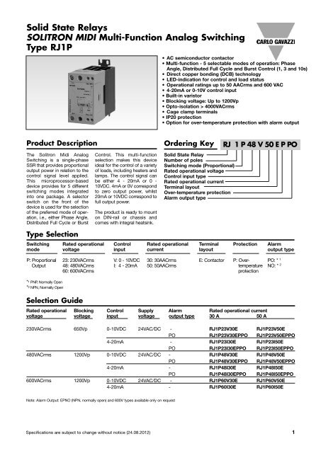
Solid State Relays<br />
SOLITRON MIDI Multi-Function Analog Switching<br />
Type RJ1P<br />
Product Description Ordering Key<br />
The Solitron Midi Analog<br />
Switching is a single-phase<br />
SSR that provides proportional<br />
output power in relation <strong>to</strong> the<br />
control signal level applied.<br />
This microprocessor-based<br />
device provides for 5 different<br />
switching modes integrated<br />
in<strong>to</strong> one package. A selec<strong>to</strong>r<br />
switch on the front of the<br />
device is used for the selection<br />
of the preferred mode of operation,<br />
i.e., either Phase Angle,<br />
Distributed Full Cycle or Burst<br />
Type Selection<br />
Control. This multi-function<br />
selection makes this device<br />
ideal for the control of a variety<br />
of loads, including heaters and<br />
lamps. The control signal can<br />
be either 4 - 20mA or 0 -<br />
10VDC. 4mA or 0V correspond<br />
<strong>to</strong> zero output power, whilst<br />
20mA or 10VDC correspond <strong>to</strong><br />
full output power.<br />
The product is ready <strong>to</strong> mount<br />
on DIN-rail or chassis and<br />
comes <strong>with</strong> integral heatsink.<br />
Rated operational Blocking Control Supply Alarm Rated operational current<br />
voltage voltage <strong>input</strong> voltage output type 30 A <strong>50</strong> A<br />
230VACrms 6<strong>50</strong>Vp 0-10VDC 24VAC/DC - RJ1P23V30E RJ1P23V<strong>50</strong>E<br />
PO RJ1P23V30EPPO RJ1P23V<strong>50</strong>EPPO<br />
4-20mA - RJ1P23I30E RJ1P23I<strong>50</strong>E<br />
PO RJ1P23I30EPPO RJ1P23I<strong>50</strong>EPPO<br />
480VACrms 1200Vp 0-10VDC 24VAC/DC - RJ1P48V30E RJ1P48V<strong>50</strong>E<br />
PO RJ1P48V30EPPO RJ1P48V<strong>50</strong>EPPO<br />
4-20mA - RJ1P48I30E RJ1P48I<strong>50</strong>E<br />
PO RJ1P48I30EPPO RJ1P48I<strong>50</strong>EPPO<br />
600VACrms 1200Vp 0-10VDC 24VAC/DC - RJ1P60V30E RJ1P60V<strong>50</strong>E<br />
4-20mA - RJ1P60I30E RJ1P60I<strong>50</strong>E<br />
Note: Alarm Output: EPNO (NPN, normally open) and 600V types available only on request<br />
• AC semiconduc<strong>to</strong>r contac<strong>to</strong>r<br />
• Multi-function - 5 selectable modes of operation: Phase<br />
Angle, Distributed Full Cycle and Burst Control (1, 3 and 10s)<br />
• Direct copper bonding (DCB) technology<br />
• LED-indication for control and load status<br />
• Operational ratings up <strong>to</strong> <strong>50</strong> AACrms and 600 VAC<br />
• 4-20mA or 0-10V control <strong>input</strong><br />
• Built-in varis<strong>to</strong>r<br />
• Blocking voltage: <strong>Up</strong> <strong>to</strong> 1200Vp<br />
• Op<strong>to</strong>-isolation > 4000VACrms<br />
• Cage clamp terminals<br />
• IP20 protection<br />
• Option for over-temperature protection <strong>with</strong> alarm output<br />
Solid State Relay<br />
Number of poles<br />
Switching mode (Proportional)<br />
Rated operational voltage<br />
Control <strong>input</strong> type<br />
Rated operational current<br />
Terminal layout<br />
Over-temperature protection<br />
Alarm output type<br />
Switching Rated operational Control Rated operational Terminal Protection Alarm<br />
mode voltage <strong>input</strong> current layout output type<br />
P: Proportional 23: 230VACrms V: 0 - 10VDC 30: 30AACrms E: Contac<strong>to</strong>r P: Over- PO: * 1<br />
Output 48: 480VACrms I: 4 - 20mA <strong>50</strong>: <strong>50</strong>AACrms temperature NO: * 2<br />
60: 600VACrms protection<br />
*1 PNP, Normally Open<br />
*2 NPN, Normally Open<br />
Selection Guide<br />
RJ 1 P 48 V <strong>50</strong> E P PO<br />
Specifications are subject <strong>to</strong> change <strong>with</strong>out notice (24.08.2012) 1
RJ1P<br />
General Specifications<br />
RJ1P23... RJ1P48... RJ1P60...<br />
Operational voltage range 90 <strong>to</strong> 265VAC 200 <strong>to</strong> 5<strong>50</strong>VAC 410 <strong>to</strong> 660VAC<br />
Blocking voltage 6<strong>50</strong>Vp 1200Vp 1200Vp<br />
Operational frequency range 45 <strong>to</strong> 65Hz 45 <strong>to</strong> 65Hz 45 <strong>to</strong> 65Hz<br />
Output power 0 <strong>to</strong> 99% 0 <strong>to</strong> 99% 0 <strong>to</strong> 99%<br />
Power fac<strong>to</strong>r ≥ 0.9 @ 230VACrms ≥ 0.9 @ 480VACrms ≥ 0.9 @ 600VACrms<br />
Load status indication Red LED Red LED Red LED<br />
Output power resolution<br />
MODE 1 Phase Angle 1/300 @ <strong>50</strong>Hz, 1/300 @ 60Hz<br />
MODE 2 Full Cycle 1/64 @ <strong>50</strong>Hz, 1/64 @ 60Hz<br />
MODE 3 Burst <strong>with</strong> 1s period 1/<strong>50</strong> @ <strong>50</strong>Hz, 1/60 @ 60Hz<br />
MODE 4 Burst <strong>with</strong> 3s period 1/1<strong>50</strong> @ <strong>50</strong>Hz, 1/180 @ 60Hz<br />
MODE 5 Burst <strong>with</strong> 10s period 1/<strong>50</strong>0 @ <strong>50</strong>Hz, 1/600 @ 60Hz<br />
Approvals UL, cUL*<br />
CE-marking Yes<br />
* Approvals pending for RJ1P...P.O models<br />
Input Specifications<br />
RJ1P..I...<br />
Current controlled <strong>input</strong><br />
Control current range 4 - 20mA<br />
Max. allowable <strong>input</strong> current <strong>50</strong>mA<br />
Pick up current 4.2mA<br />
Drop out current 3.9mA<br />
Control status indication Green LED<br />
Reverse polarity protected Yes<br />
Voltage drop 10VDC @ 20mA<br />
Note: the use of twisted pair cable for the control <strong>input</strong> is recommended<br />
Output Specifications<br />
RJ1P..V...<br />
Voltage controlled <strong>input</strong><br />
Supply voltage range, Vss 20 - 28VAC/DC<br />
Supply current 18mA @ 24VDC<br />
23mA @ 24VAC<br />
Control voltage range, Vcc 0 - 10VDC<br />
Control <strong>input</strong> current 0.1mA @ 10VDC<br />
Reverse polarity protected Yes<br />
Pick up voltage 0.5VDC<br />
Drop out voltage 0.05VDC<br />
Control status indication Green LED<br />
RJ1P...30 RJ1P...<strong>50</strong><br />
Rated operational current<br />
AC51 @Ta=25ºC 30AACrms <strong>50</strong>AACrms<br />
Min. operational current<br />
Rep. overload current t=1 s<br />
1<strong>50</strong>mAACrms <strong>50</strong>0mAACrms<br />
(Tj init.=25°C)<br />
Non-rep. surge current t=10 ms<br />
< 55AACrms < 200AACrms<br />
(Tj init.=25°C)<br />
Off-state leakage current,<br />
325Ap 1900Ap<br />
@ rated voltage and frequency < 3 mArms < 3 mArms<br />
I2t for fusing t=10 ms 525A2s 18000A2s On-state voltage drop @ rated current 1.6Vrms 1.6Vrms<br />
Critical dV/dt off-state 1000V/µs 1000V/µs<br />
Isolation<br />
Rated isolation voltage<br />
Input <strong>to</strong> output ≥ 4000 VACrms<br />
Output <strong>to</strong> case ≥ 4000 VACrms<br />
Thermal Specifications<br />
Operating temperature -20 <strong>to</strong> +70ºC (-4 <strong>to</strong> +158 ˚F)<br />
S<strong>to</strong>rage temperature -40 <strong>to</strong> +100ºC (-40 <strong>to</strong> +212 ˚F)<br />
2 Specifications are subject <strong>to</strong> change <strong>with</strong>out notice (24.08.2012)
RJ1P<br />
Connection Examples<br />
~<br />
~<br />
~<br />
~<br />
LOAD<br />
LOAD<br />
1L1 5A3 3A1<br />
2T1<br />
2T1<br />
- + 4 - 20mA<br />
6A4 4A2<br />
0V -<br />
1L1 5A3 3A1<br />
6A4 4A2<br />
+ 4 - 20 mA<br />
24VDC/AC + - Over-temperature<br />
Alarm Output<br />
~<br />
~<br />
~<br />
~<br />
LOAD<br />
LOAD<br />
1L1 5A3 3A1<br />
2T1<br />
0V -<br />
6A4 4A2<br />
+ 10VDC<br />
24VDC/AC + - 0V<br />
3A1 - 5A3: Control <strong>input</strong> current 3A1 - 5A3: Control <strong>input</strong> voltage, Vcc<br />
Example: RJ1P48I..E<br />
4A2 - 6A4: Supply <strong>input</strong> voltage, Vss<br />
Example: RJ1P48V..E<br />
1L1 5A3 3A1<br />
2T1<br />
0V -<br />
6A4 4A2<br />
+ 10 VDC<br />
24VDC/AC + - Over-temperature<br />
Alarm Output<br />
Note: For the RJ1P..V..E, it is possible <strong>to</strong> have the ground terminals of the supply and control power supplies used commoned. In the case, this common<br />
ground is connected either <strong>to</strong> terminal A2 or terminal A3. This is only applicable when a 24 VDC supply voltage is used. There should be no external<br />
direct link from Terminal A2 <strong>to</strong> Terminal A3.<br />
Alarm Specifications<br />
3A1 - 5A3 : Control Input Current Ic (4-20mA)<br />
6A4 : Supply Voltage Vss (24VDC)<br />
4A2 : Alarm output, NPN Normally Open<br />
Example: RJ1P48I..PNO<br />
Output current ≤ <strong>50</strong> mADC<br />
Output voltage<br />
NPN 1V<br />
PNP (Voltage version) Vcc - 1 - 82 io<br />
PNP (Current version) Vcc - 3 (0.<strong>50</strong> mA)<br />
No. of outputs in parallel ≤ <strong>50</strong><br />
3A1 - 5A3 : Control Input Voltage Vcc (0-10V)<br />
6A4 : Supply Voltage Vss (24VAC/ DC)<br />
4A2 : Alarm output, PNP Normally Open<br />
Example: RJ1P48I..EPPO<br />
Specifications are subject <strong>to</strong> change <strong>with</strong>out notice (24.08.2012) 3
RJ1P<br />
Operation<br />
MODE 1: The Phase Angle<br />
switching mode works in<br />
accordance <strong>with</strong> the phase<br />
angle control principle, i.e. the<br />
output switching point in the<br />
AC sine wave depends on the<br />
signal level applied at the<br />
<strong>input</strong>. The relay switches off<br />
everytime the output current<br />
crosses zero.<br />
MODE 2: The Distributed<br />
mode provides a number of<br />
full cycles, evenly distributed<br />
over a fixed period of 1.28s @<br />
<strong>50</strong>Hz (1.07s @ 60Hz), depending<br />
on the control <strong>input</strong>.<br />
Terminal Layout<br />
Transfer characteristics<br />
Dissipation Curve<br />
W<br />
<strong>50</strong><br />
40<br />
30<br />
20<br />
10<br />
0<br />
MODE 3, 4, 5: The Burst<br />
Switching mode generates a<br />
number of full cycles, depending<br />
on the control <strong>input</strong> over<br />
fixed periods of 1s, 3s or 10s<br />
for MODES 3, 4 and 5 respectively.<br />
Modes 2, 3, 4 and 5 use the<br />
zero switching principle, thus<br />
ensuring a reduced level of<br />
radiated and wire-conducted<br />
noise. The Distributed and<br />
Burst Switching modes are not<br />
recommended for light control<br />
due <strong>to</strong> light-flickering.<br />
30A<br />
<strong>50</strong>A<br />
0 10 20 30 40 <strong>50</strong> 60<br />
AACrms<br />
LED INDICATION<br />
The <strong>to</strong>p RED LED indicates<br />
the load status. It goes ON<br />
whenever the load is activated,<br />
and in the RJ1P…P..O<br />
models this led is used <strong>to</strong> indicate<br />
an over temperature<br />
alarm. The Green LED gives<br />
indication of the status of the<br />
control <strong>input</strong>.<br />
<strong>Up</strong>on application of control<br />
current (for the RJ1P..I..) <strong>to</strong> terminals<br />
A1 – A3, the Green LED<br />
will be dimly lit, <strong>with</strong> its intensity<br />
increasing <strong>with</strong> an<br />
increase in control current.<br />
Mode Selection<br />
Output power as a function of control <strong>input</strong> MODE 1 Phase Angle Switching<br />
Control Control Output MODE 2 Distributed Control<br />
Current (mA) Voltage (VDC) Power (%) MODE 3 Burst Switching (1 sec. period)<br />
4 0 0<br />
MODE 4 Burst Switching (3 sec. period)<br />
8 2.5 25<br />
MODE 5 Burst Switching (10 sec. period)<br />
12 5 <strong>50</strong><br />
16 7.5 75<br />
20 10 99<br />
For the RJ1P..V.. the Green<br />
LED will be ON (flickering)<br />
upon application of the supply<br />
voltage <strong>to</strong> terminals A3 – A4.<br />
In RJ1P..VE only, terminals A3<br />
and A2 are shorted. Once a<br />
control voltage is applied <strong>to</strong><br />
terminals A1 – A3, the Green<br />
LED will be fully ON, if greater<br />
than a threshold voltage<br />
(approx 0.5V). Note that the<br />
first time the device (voltage<br />
control version) is <strong>to</strong> be activated,<br />
the mains voltage has<br />
<strong>to</strong> be present for the Green<br />
LED <strong>to</strong> indicate the control<br />
status.<br />
4 Specifications are subject <strong>to</strong> change <strong>with</strong>out notice (24.08.2012)
RJ1P<br />
Functional Diagram<br />
Dimensions<br />
Alarm Output<br />
Supply<br />
Control <strong>input</strong><br />
MODE 1<br />
Phase Angle<br />
A2<br />
A4 (+)<br />
A3 (-)<br />
A1 (+)<br />
MODE 2<br />
Distributed Full Cycle<br />
MODE 3, 4, 5<br />
Burst 1s, 3s, 10s<br />
4, 5<br />
All dimensions in mm.<br />
Specifications are subject <strong>to</strong> change <strong>with</strong>out notice (24.08.2012) 5<br />
IC<br />
1 period = 64 cycles<br />
1 period = 1s, 3s or 10s<br />
Housing Specifications<br />
Weight Approx. 430 g<br />
Housing material PBT Flame retardant<br />
Control terminal cable size<br />
Min 1 x 0.5 mm 2 (1 x AWG20)<br />
Max 1 x 4.0 mm 2 (1 x AWG12) or<br />
2 x 2.5 mm 2 (2 x AWG14)<br />
Mounting <strong>to</strong>rque max. 0.6 Nm Posidriv 0 bit<br />
Control terminal screw M3<br />
Power terminal cable size<br />
Min 1 x 4 mm 2 (1 x AWG12)<br />
Max 1 x 25 mm 2 (1 x AWG3) or<br />
2 x 10 mm 2 (2 x AWG6)<br />
Mounting <strong>to</strong>rque max. 2.5 Nm Posidriv 2 bit<br />
Power terminal screw M5
RJ1P<br />
Derating vs. Spacing Curves<br />
Load Current (AACrms)<br />
Load Current (AACrms)<br />
55<br />
<strong>50</strong><br />
45<br />
40<br />
35<br />
30<br />
25<br />
20<br />
15<br />
10<br />
35<br />
30<br />
25<br />
20<br />
15<br />
10<br />
Note: Based on 100% output power<br />
20 25 30 35 40 45 <strong>50</strong> 55 60 65 70<br />
Surrounding temp. (˚C)<br />
20 25 30 35 40 45 <strong>50</strong> 55 60 65 70<br />
Surrounding temp. (˚C)<br />
RJ1P...30<br />
RJ1P...<strong>50</strong><br />
6 Specifications are subject <strong>to</strong> change <strong>with</strong>out notice (24.08.2012)<br />
22.5mm<br />
6.0mm<br />
0.0mm<br />
22.5mm<br />
6.0mm<br />
0.0mm
RJ1P<br />
Functional Diagram<br />
Mains Supply<br />
24V Supply<br />
Control Input<br />
Green LED<br />
Red LED<br />
Output<br />
Alarm PNP*<br />
Alarm NPN*<br />
Over Temperature Sensing *<br />
Mains Supply<br />
24V Supply *<br />
Control Input<br />
Green LED<br />
Red LED<br />
Output<br />
Alarm PNP*<br />
Alarm NPN*<br />
Over Temperature Sensing *<br />
* Applicable <strong>to</strong> RJ1P...P..O models only<br />
* Applicable <strong>to</strong> RJ1P...P..O models only<br />
RJ1P..V..E..<br />
RJ1P..I..E..<br />
Specifications are subject <strong>to</strong> change <strong>with</strong>out notice (24.08.2012) 7