ROTARY - SM18 INSTALLATION MANUAL.pdf - Atlantic Auto ...
ROTARY - SM18 INSTALLATION MANUAL.pdf - Atlantic Auto ...
ROTARY - SM18 INSTALLATION MANUAL.pdf - Atlantic Auto ...

Create successful ePaper yourself
Turn your PDF publications into a flip-book with our unique Google optimized e-Paper software.
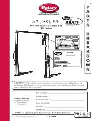
<strong>SM18</strong><br />
(000-017 Series)<br />
Capacity 18,000 lbs. (9,000 lbs. per axle)<br />
Four Post Surface Mounted Lift<br />
Maximum Wheelbases: 194" & 230"<br />
Minimum Wheelbase: 126"<br />
LP20111<br />
© September 2007 by Rotary Lift. CO6953.7 IN20195<br />
Rev. E 09/25/2007<br />
I<br />
N<br />
S<br />
T<br />
A<br />
L<br />
L<br />
A<br />
T<br />
I<br />
O<br />
N<br />
I<br />
N<br />
S<br />
T<br />
R<br />
U<br />
C<br />
T<br />
I<br />
O<br />
N<br />
S
4'-6" Min. To<br />
Nearest<br />
Obstruction<br />
APPROACH<br />
Fig. 1<br />
REAR<br />
Left Runway<br />
Right Runway<br />
Read and understand these instructions<br />
completely before proceeding with lift installation.<br />
1. Lift Location: Use architects plan when available to locate lift.<br />
Fig. 1 shows dimensions of a typical bay layout. For power unit<br />
at right front, rotate lift 180°, leaving ramp/chocks and wheel<br />
stops in original position. Lift floor area should be level.<br />
WARNING DO NOT install on asphalt or other similar<br />
unstable surface. Columns are supported only by anchors in<br />
floor<br />
2. Ceiling or overhead clearance must be 80” plus height of tallest<br />
vehicle.<br />
Fig. 2<br />
transit<br />
target<br />
COLUMN SHIM ESTIMATES<br />
Installation Instruction<br />
C<br />
LIFT CLEARANCE<br />
2<br />
2’–0” Min. To<br />
Nearest<br />
Obstruction<br />
6'-6" Min.<br />
To<br />
Nearest Obstruction<br />
6'-6" Min.<br />
To<br />
Nearest Obstruction<br />
FRONT<br />
3. Estimating Column Shim requirements:<br />
In the following section, the terms “highest” and “lowest”<br />
refer to elevation of floor.<br />
A. Mark locations where lift columns will be<br />
positioned in bay.<br />
B. Place target at column positions and record<br />
readings, Fig. 2.<br />
C. Find the highest of the four locations. Find the<br />
difference between the reading at each of the<br />
remaining three columns and the highest reading.<br />
D. The difference is the estimated amount of shim<br />
thickness needed at each column.<br />
Dimension at highest position minus other position<br />
= shim thickness required
Fig. 3<br />
Left Rear<br />
Cable (#3)<br />
Right Front<br />
Cable (#2)<br />
FRONT<br />
Yoke End<br />
Right Rear<br />
Cable (#4)<br />
Left Front<br />
Cable (#1)<br />
Note: Maximum shim thickness is 1/2" per column using<br />
shims and anchors provided with lift. Shim<br />
thickness of 2" is possible by using optional shim<br />
kit #FC5393. Contact your authorized Rotary<br />
Parts Distributor for ordering information.<br />
4. Runway and Yoke Tube Assembly:<br />
A. Determine direction of approach in bay.<br />
B. Position left runway in bay with hydraulic<br />
cylinder hose connection to rear of bay. Cables and<br />
sheaves are pre-assembled in runway. Runway<br />
needs to be up off floor so shipping restraints can be<br />
removed from cable ends, air and hydraulic lines, and<br />
cylinder rod. Pull cable ends, air, and hydraulic lines out<br />
for assembly. Make sure cables are in proper sheave<br />
grooves, Fig. 3.<br />
CABLES IN PROPER SHEAVE GROOVES<br />
Cable<br />
Runway<br />
Sheave<br />
Front Wheel Chock<br />
FEED CABLE ENDS THROUGH YOKE OPENINGS<br />
3<br />
Runway Bolt<br />
Left Rear<br />
Cable (#3)<br />
Cable<br />
Right Runway<br />
Yoke End<br />
REAR<br />
Front Wheel Chock<br />
Runway Bolt - 1 / 2 " X 1 5 / 8 " HHCS<br />
Left Runway<br />
Right Rear<br />
Cable (#4)<br />
C. Position front and rear yokes at respective ends of<br />
runway, Fig. 1. The opening in the side of the<br />
yokes should be lined up with the cable sheaves in<br />
the runway ends. Feed cable ends through yoke<br />
openings, Fig. 4 and 9. Do not assemble sheaves<br />
in yoke ends at this time.<br />
IMPORTANT Be sure cables are not crossed inside<br />
yoke.<br />
Fig. 4
5. Attaching Runways:<br />
With the openings in the front and rear yoke tube sides lined<br />
up with the left runway ends, align the two (2) holes in the top<br />
of the front yoke tubes with the slots in the runway end plates<br />
and the holes in the front wheel stops. Bolt wheel stops and<br />
runway to the yoke using two 1/2” x 15/8” hex flange bolts,<br />
Fig. 5a<br />
LATCH BAR IN COLUMN<br />
Fig. 4. Repeat for the rear end. Align the slots of the right<br />
runway end plates with the holes in the yoke tube. Bolt front<br />
wheel stop and runway into place.<br />
Latch Bar<br />
Fig. 6<br />
Adjustment Nut<br />
Jam Nut<br />
Latch Bar<br />
Threaded Stud<br />
LATCH BAR<br />
CROSS SECTION<br />
LATCH BAR OFFSET<br />
This side<br />
faces out<br />
6. Column and Yoke Assembly:<br />
A. Place the power unit column at the left rear<br />
corner of the lift. The hydraulic cylinder<br />
connection in the left runway should be visible<br />
from this corner. Position remaining three<br />
columns.<br />
B. Thread the jam nut down the threaded stud as far<br />
as possible. Stick rubber bumper to bottom of latch<br />
bar, see Fig. 7. Place the latch bar in the back of the<br />
column, Fig. 5a. The latch bar is offset from the center<br />
line of the threaded stud (inset Fig. 6). The latch bar should<br />
be oriented toward the back of the column from center line<br />
of the threaded stud.<br />
C. Place FRL Bracket on top of power unit column.<br />
Guide the threaded stud through the hole in the<br />
column top plate and bracket, Fig. 5b. Then thread<br />
the adjustment nut down the threaded stud until<br />
the nut and top plate are flush, Fig. 5b. Repeat for<br />
other columns.<br />
4<br />
#8-32NC x 1-3/4"<br />
Hex SHCS<br />
Latch Bar<br />
Rubber<br />
Bumper<br />
Column<br />
Slider<br />
FRL<br />
Threaded Stud<br />
Adjustment Nut<br />
Jam Nut<br />
Latch Bar<br />
Yoke<br />
ATTACH FRL<br />
Pull Latch Bar up<br />
above sliders.<br />
ATTACH SLIDERS<br />
Jam Nut<br />
Nut<br />
Washer<br />
5/16”–18NC<br />
BHS x 1/2” lg.<br />
D. Start yoke end into the column, allowing slider<br />
bolt holes to stay exposed, Fig. 7. Apply thread<br />
locking compound to screw threads then bolt<br />
sliders onto each side of the yoke end with 5/16"-<br />
18NC screws provided. When both sliders are<br />
attached, push column toward yoke end until<br />
sliders touch latch bar.<br />
E. Raise latch bar above sliders and move column<br />
toward yoke until the sliders contact the back of<br />
the column. Lower the latch bar into the sliders.<br />
Tighten latch bar jam nut against column top<br />
plate. Run latch bar adjustment nut down and<br />
tighten. The latch bar should engage the sliders<br />
for at least 1" when the lift is completely lowered.<br />
Repeat this procedure for each yoke end and<br />
column.<br />
F. Install yoke end sheaves and plastic spacers,<br />
Fig. 8. A plastic spacer is placed on each side of the<br />
sheave, inset Fig. 8.<br />
FRL Bracket<br />
#8-32NC Nylon<br />
Lock Nut<br />
Threaded Cable<br />
Power Unit<br />
Column<br />
Fig. 5b<br />
Fig. 7
Fig. 8<br />
5 /16 ” Hex Hd.<br />
Bolt<br />
Sheave Pin<br />
Left Front<br />
1 /4 ”–20 x 1 / 2 ” lg. Type “T”<br />
Hex. Hd. Tapping Screw<br />
1 /4 ” Plain Washer<br />
Plastic Spacers<br />
Sheave<br />
Rubber<br />
Guard<br />
Left Rear<br />
Jam Nut<br />
Washer<br />
CABLE ROPING<br />
5<br />
Yoke<br />
End<br />
SHEAVE <strong>INSTALLATION</strong><br />
Nut<br />
Right Front<br />
Latch Bar Adjustment<br />
Stud<br />
Plastic<br />
Spacers<br />
Sheave<br />
Yoke Side<br />
Plate<br />
Column<br />
TOP VIEW (top removed)<br />
Do Not Cross Cables<br />
at Either End<br />
Right Rear<br />
Fig. 9
Note: Failure to install plastic spacer will result in<br />
premature failure and void warranty.<br />
G. Retain with sheave pin and 5/16” button head<br />
machine screw. Attach each cable to column top<br />
plate with nut, jam nut, and washer, Fig. 8. Install<br />
rubber sheave guard on each yoke end, Fig. 8.<br />
Roping diagram shows a view of completed roping,<br />
Fig. 9. IMPORTANT Be sure cable is located in the<br />
sheave groove.<br />
Fig. 10<br />
Column<br />
7. Column Anchoring:<br />
A. Concrete shall have a compression strength of at least<br />
3,000 PSI and a typical slab thickness of 5-1/2” to 6” and<br />
should sustain 2000# anchor load.<br />
B. Keep columns square to center line of lift. Check lift loca-<br />
tion in the bay, Fig. 1. Check dimensions side-to-side,<br />
front-to-rear, and diagonally. Diagonals must be equal to<br />
within 1/4", Fig. 11.<br />
C. Move column towards yoke until the sliders contact the<br />
back of column, center yoke in column, Fig. 10.<br />
D. Place shims (estimated in Step 3) under each<br />
column. Drill four 5/8” diameter holes through<br />
concrete floor using base holes as guide, Fig. 13.<br />
Width and length<br />
measurements are made<br />
from column sides,<br />
NOT column base plate.<br />
Diagonals are measured<br />
from out side corner of<br />
runways.<br />
APPROACH<br />
Latch Bar<br />
Slider<br />
Yoke<br />
COLUMN CROSS SECTION<br />
Left Runway<br />
(000/006/010/016) - 211-15/16” Ref.<br />
(001/007/011/017) - 247-15/16” Ref.<br />
Diagonals<br />
within 1 / 4 "<br />
Drill holes using 5 / 8 "<br />
carbide tipped masonry<br />
drill bit per ANSI standard<br />
B94.12.1977<br />
Remove washer. Run nut down, just<br />
below impact section of stud. Drive<br />
anchor into hole until nut contacts base.<br />
Right Runway<br />
Fig. 11<br />
6 CHECK DIAGONALS<br />
ANCHOR HOLES<br />
Replace washer.<br />
Tighten nut to<br />
35-45 ft./lbs.<br />
Fig. 12<br />
122 3 / 16 ” Ref.
Fig. 13<br />
Fig. 14<br />
Nut<br />
Anchor<br />
Washer<br />
INSERT ANCHORS<br />
Shim ( 1 / 2 ” Max.)<br />
Repeat for other columns.<br />
E. Insert base anchors, Fig.'s 12 and 13.<br />
F. Tighten nuts, Fig. 12. Check columns for plumb<br />
and level. Re-shim if necessary. Torque anchor<br />
bolts to 35-45 ft. lbs., Fig. 12.<br />
G. If anchor bolts do not hold when torqued to re-<br />
quired amount, concrete must be replaced. Saw<br />
cut and remove 24” x 24” square area under each<br />
column base. Repour with reinforced 3000#<br />
minimum concrete to depth of 6", keying new<br />
concrete under existing floor.<br />
B<br />
RUNWAY LEVELING<br />
A<br />
7<br />
8. Runway Leveling:<br />
A. Use an engineer’s automatic level (transit).<br />
Locate the Level at a convenient location in the<br />
shop that allows an unobstructed view of all four<br />
corners of the lift’s runways. Follow the Level<br />
manufacturer’s instructions for proper setup. Be<br />
sure it is adjusted level in all directions. Readjust if tripod<br />
or Level is bumped or disturbed.<br />
B. Make sure yoke tubes rest on column base plate.<br />
Target Scale<br />
TARGET SCALE<br />
C. First place the Level target at the highest corner<br />
of the lift. Place it on the runway center line<br />
within 6” of yoke tube, whichever one is located<br />
over highest point. This will be referred to as<br />
target “A” position. Beginning with target “A”<br />
position, Fig. 14, sight the Level to the target and<br />
mark the number or the graduation on the inch<br />
scale of the target that aligns to the crosshairs of<br />
the Level, Fig. 15.<br />
Note: Use a pencil, marking pen or attach a paper clip<br />
onto the target scale at the crosshair reference.<br />
C<br />
23 24 25 11 12 13<br />
D<br />
Fig. 15
D. Next, move the target and place it on the runway at point “B”,<br />
Fig. 14. Rotate the Level and focus on the target scale. Adjust<br />
the column at “B” using shims under base plate, Fig. 13, until the<br />
crosshairs of Level align to reference mark on the target<br />
scale. Repeat for points C and D.<br />
Runways Should Be Level. Maximum Tolerance Side To SideAnd<br />
Front To Rear 1/8”<br />
9. Cable Adjustment:<br />
Adjust cable with lift fully lowered. Loosen jam nut<br />
and tighten nut on cable stud on top of column until yoke end<br />
raises 1/4". Back off nut one turn. Retighten jam nut. Repeat<br />
for all four cables. Refer to Fig. 8.<br />
IMPORTANT Cables must fit in slack cable arm rollers, Fig.16.<br />
Fig. 16<br />
Push nuts hold<br />
bolts to brackets<br />
Use (4)5/16"-18NC<br />
x 1-1/2" lg. HHCS<br />
Use (4)5/16"-18NC<br />
Nuts and 5/16" Star<br />
Washers<br />
Cable<br />
Air Valve Bracket<br />
Slack Cable<br />
Arm Roller<br />
CABLE IN SLACK CABLE ARM<br />
Raise Switch<br />
CAPACITY<br />
18,000 LBS.<br />
Lowering<br />
Valve<br />
Fill Breather Cap<br />
FRONT VIEW<br />
AIR BRACKET<br />
Fig. 17 MOUNTING AIR VALVE BRACKET<br />
Sheave<br />
PUSH TO<br />
RELEASE<br />
LATCHES<br />
NP280<br />
8<br />
10. Power Unit:<br />
A. Align Latch Release Air Valve Bracket with holes<br />
in right side of Column Bracket. Put four 5/16" x<br />
1 1/2" hex bolts through holes in Air Valve Bracket<br />
and Column Bracket, using push nuts to hold in<br />
place, Fig. 17.<br />
B. Mount power unit, with motor up, to column<br />
bracket and install lock washers and nuts. Run<br />
hydraulic hose from runway through grommet in side<br />
of runway to power unit output port, Fig. 19. DO<br />
NOT use Teflon tape on hydraulic hose connec-<br />
tions. Install and hand tighten elbow to pump<br />
until O-ring is seated and elbow should be ori-<br />
ented downward. Tighten locknut to 35-40 ft. lbs.<br />
Install enclosed Capacity label on power unit.<br />
11. Electrical: Have a certified electrician run appropriate power<br />
supply to motor, Fig. 21 & 22. Size wire for 20 amp circuit. See<br />
Motor Operating Data Table.<br />
CAUTION Never operate the motor on line voltage less than<br />
208V. Motor damage may occur.<br />
IMPORTANT: Use separate circuit for each power unit. Protect<br />
each circuit with time delay fuse or circuit breaker. For single<br />
phase 208-230V, use 20 amp fuse. Three phase 208-240V, use<br />
15 amp fuse. For three phase 400V and above, use 10 amp<br />
fuse. For wiring see Fig. 20, & Fig. 21. All wiring must comply<br />
with NEC and all local electrical codes.<br />
Elbow<br />
Crimped Hose<br />
Sleeve (Typical)<br />
Fig. 18
Fig. 19<br />
Cable Ties<br />
Air Line<br />
Hydraulic<br />
Hose<br />
Note: 60Hz. single phase motor CAN NOT be run on 50Hz. line<br />
without a physical change in the motor.<br />
WARNING Risk of explosion. This equipment has internal<br />
arcing or sparking parts which should not be exposed to flammable<br />
vapors. It should not be located in a recessed area or<br />
below floor level.<br />
12. Hydraulic Fluid Filling:<br />
System capacity is thirteen (13) quarts. Use Dexron III ATF.<br />
Remove fill/breather, Fig. 19. Pour in hydraulic fluid until it<br />
reaches the Fill Line. Replace fill/breather. Start motor and<br />
raise lift to full rise. Lower onto latches.<br />
Note: If fill/breather, Fig. 19, is lost or broken, order<br />
replacement.<br />
9<br />
Column<br />
Fill/Breather Cap<br />
Fill Line<br />
Power Unit
208-230V 60Hz<br />
Single Phase<br />
Black White<br />
Green<br />
Attach ground wire here.<br />
Attach ground wire to<br />
screws provided.<br />
Fig. 20<br />
Attach black wire<br />
to one motor wire.<br />
Attach white<br />
wire to one<br />
motor wire.<br />
10<br />
230V 60Hz<br />
Single Ph<br />
Black<br />
Green<br />
White<br />
Single Phase Power Unit<br />
MOTOR OPERATING DATA TABLE - SINGLE PHASE<br />
LINE VOLTAGE RUNNING MOTOR VOLTAGE RANGE<br />
208-230V 50Hz. 197-253V<br />
208-230V 60Hz. 197-253V<br />
Note: 60Hz. Single phase motor CAN NOT be run on 50Hz. line<br />
without a physical change in the motor.<br />
Up<br />
Switch<br />
Black Black<br />
White<br />
M
NOTE: Two Different Drum Switches were used<br />
please select one of the two options below.<br />
NOTES:<br />
1. Unit not suitable for use in unusual conditions. Contact<br />
Rotary for moisture and dust environment duty unit.<br />
2. Control Box must be field mounted to power unit.<br />
3. Motor rotation is counter clockwise from top of motor.<br />
Fig. 21<br />
3 Phase<br />
Supply<br />
3 Phase<br />
Supply<br />
L1<br />
L2<br />
L3<br />
PE<br />
L1<br />
L2<br />
L3<br />
PE<br />
1<br />
5<br />
7<br />
1<br />
3<br />
5<br />
Three Phase Power Unit<br />
2<br />
6<br />
8<br />
DRUM<br />
SWITCH<br />
2<br />
4<br />
6<br />
DRUM<br />
SWITCH<br />
MOTOR OPERATING DATA TABLE - THREE PHASE<br />
LINE VOLTAGE RUNNING MOTOR VOLTAGE RANGE<br />
208-240V 50/60Hz. 197-253V<br />
400V 50Hz. 360-440V<br />
440-480V 50/60Hz. 396V-528V<br />
575V 60Hz. 518V-632V<br />
MOTOR<br />
(4) M5 x 45 PHMS, Plated<br />
MOTOR<br />
L3<br />
L2<br />
L1<br />
Steel Spacer<br />
Drum Switch<br />
And Cover<br />
T3<br />
T2<br />
T1<br />
Gasket<br />
11<br />
T9<br />
T8<br />
T7<br />
208-240V<br />
50/60Hz. 3Ø<br />
(4) M5 x 10 PHMS, Plated<br />
Capacitor Box To Power Unit<br />
T6<br />
T5<br />
T4<br />
FOR 3 Ø POWER<br />
UNITS: Attach Box using<br />
M5 x 10 PHMS, Plated<br />
Capacitor Box Attachment<br />
Option One<br />
L3<br />
L2<br />
L1<br />
Re-seal Between<br />
Box And Spacer<br />
With Silicone<br />
Sealer<br />
Capacitor Box Attachment<br />
Option Two<br />
T3<br />
T2<br />
T1<br />
T9 T6<br />
T8 T5<br />
T7 T4<br />
440-480V 50/60 Hz. 3Ø<br />
380-400V 50 Hz. 3Ø<br />
Capacitor<br />
Box<br />
V2<br />
U2<br />
W2<br />
W1<br />
V1<br />
U1<br />
575V 60 Hz. 3Ø<br />
T3<br />
T2<br />
T1
13. Air Line Connections:<br />
Note: Locking latches require 90 psi. min. to 120 psi. max. air pressure.<br />
IMPORTANT A filter/regulator/lubricator must be installed on<br />
air supply at lift. Failure to do so will void the warranty.<br />
A. Lift should be at full height and lowered on latches.<br />
B. Connect air valve to Reducing Tee, Fig. 22. Cut provided 1/4”<br />
air line tubing with sharp blade to length as required. Tubing must<br />
be cut square with no burrs.<br />
Note: To assemble air line tubing into fitting, use firm, manual<br />
pressure to push tubing into fitting until it bottoms, Fig. 23. If<br />
removal of the air line tubing from the fitting is ever required, hold<br />
Push Sleeve in (against fitting) and, at the same time, pull out on<br />
tubing.<br />
C. Use button collar to secure the air valve to the air valve<br />
bracket, Fig. 22.<br />
D. Attach enclosed NP280 decal (ACTUATE TO RELEASE LATCH-<br />
ES) below button on air valve bracket, Fig. 17. Run 1/4” air line<br />
from air valve to the slot in the fixed runway. Cut airline and attach<br />
a Tee, Fig. 25.<br />
To Main Air<br />
Supply<br />
FRL<br />
1/4" Air Line<br />
From FRL<br />
to Reducing Tee<br />
3/8" Air Line<br />
PAY ATTENTION TO<br />
NUMBERING SEQUENCE<br />
ON AIR VALVE<br />
12<br />
E. Run 1/4” air line from the Tee of the runway grommet through<br />
the guide tubes on the inside wall of the runway to the Tee in the<br />
front yoke, Fig. 25.<br />
F. Run 1/4” air line from the Tee at the runway grommet to the Tee<br />
in the rear yoke.<br />
G. Run 3/8" air line from existing facility main air supply to the FRL.<br />
Run 3/8" air line from FRL to reducing tee, Fig. 22.<br />
H. Check for air leaks by depressing air valve. Repair as required.<br />
I. Use provided cable ties to tie air line to hydraulic hose between<br />
power unit and lift.<br />
J. Actuate air valve and check latch operation on all four corners.<br />
The locking latches should pull in beyond yoke ends to clear the<br />
latch bars located in all four columns, Fig. 24.<br />
Reducing<br />
Tee<br />
To Slot in runway<br />
for Air Locks<br />
3<br />
1<br />
2<br />
Push<br />
Sleeve<br />
Lifts without internal<br />
air line get plug<br />
3/8" Air Line<br />
Air Valve<br />
AIR LINE INTO FITTING<br />
To Runway for<br />
Rolling Jacks (Only<br />
for use on runways<br />
with internal air<br />
Air Valve Bracket<br />
Air Line<br />
Tubing<br />
Fig. 22<br />
Fig. 23
K. Use cable ties provided to tie 3/8” air supply to electrical supply<br />
conduit at approximately 2’0” intervals.<br />
14. Bleeding:<br />
Lift must be fully lowered before changing or adding fluid. Raise<br />
and lower lift six times. The cylinder is self-bleeding. After bleeding<br />
system, fluid level in power unit reservoir may be down. Add<br />
more ATF, if necessary, following instructions in Step 12.<br />
To pressure test, run lift to full rise and run motor for approximately<br />
5 seconds. Stop and check all fittings and hose connections.<br />
Tighten or reseal if required. Lower lift. If fill/breather, Fig. 19, is<br />
lost or broken, order replacement.<br />
Note: Some test fluid may be spilled from the cylinder breather<br />
vent during bleeding of the system.<br />
15. Assemble ramp/chocks to rear of runways using hinge pins<br />
and cotter pins, Fig. 26<br />
16. Final Adjustments:<br />
A. Load vehicle such as an RV onto lift.<br />
B. Raise lift to full height. You will hear the locking latch click<br />
through all 12 latch slots.<br />
C. Lower lift onto topmost latch position.<br />
D. Check latch clearance.<br />
1. Starting with the right front column: use a<br />
straight edge to mark the yoke height on the<br />
column, Fig. 27.<br />
2. Raise lift to full height again. Mark second<br />
position. If gap between two marks is<br />
less than 2", adjust locking latch bar to reach<br />
clearance of 2".<br />
a. Adjust locking latch bar adjusting nut so<br />
that the bottom of the topmost latch bar<br />
slot is at least 2" below locking latch,<br />
Fig. 28. After adjustment, tighten jam nut<br />
underneath column top plate, Fig. 28.<br />
b. If entire 2" clearance cannot be attained by<br />
adjusting the locking latch bar, adjust the<br />
cable stud. Loosen cable jam nut, Fig. 27,<br />
and turn adjusting nut to raise the locking<br />
latch 2" above bottom of latch bar slot.<br />
Tighten cable jam nut.<br />
3. Lower lift and remove vehicle.<br />
E. Raise the lift to full height. Listen and watchs the locking<br />
latches click in place. Synchronize the other three columns<br />
with the right front column by adjusting their cables so all four<br />
latches click at same time. Tighten jam nuts.<br />
13<br />
Fig. 24<br />
Yoke<br />
Cylinder<br />
Locking<br />
Latch Bar<br />
Locking Latch<br />
LATCHES SHOULD CLEAR LATCH BARS
Fig. 25<br />
Tee<br />
1 /4 ” Air Line To Lift<br />
Tee<br />
CAUTION When making changes to adjustment nuts on<br />
cable end or latch bar stud always leave at least two threads<br />
showing between nut and end.<br />
Note: Latches may not click in at the same time when vehicle is<br />
being raised. They should be close. Be sure all four corners<br />
have passed the locking latch bar slot before lowering lift on<br />
locking latches.<br />
Note: All bolts and nuts mentioned in this booklet are grade 5<br />
unless otherwise stated.<br />
IMPORTANT Cotter pins are usually good for one time use<br />
only. Replace any cotter pin, if removed, with a new cotter pin.<br />
Fig. 26<br />
Cotter Pin Should Be On<br />
Outside Of Runway<br />
Ramp/ Chock<br />
RAMP CHOCK ATTACHMENT<br />
Runway<br />
1 /4 ” Air Line in Runway<br />
RUNWAY AIR LINE<br />
14<br />
Left Runway<br />
Cylinder<br />
Assembly<br />
17. Rubber Stop: Install (2) rubber stops in 1/2" holes 83" from<br />
front of runways. Attach using 1/4" Bolt, and Flanged Nut, Fig.<br />
29. Attach (2) additional rubber stops 133" from front of runway<br />
on 000/006/010/016 Series lifts. Attach 167-1/2" from front<br />
of runway for 001/007/011/017 Series lifts.<br />
Cable Jam Nut<br />
and Adjusting Nut<br />
Washer<br />
Mark position of<br />
yoke at topmost<br />
latch position<br />
Tee<br />
Locking Latch Bar Adjustment<br />
Stud<br />
MARK THE YOKE HEIGHT<br />
Locking Latch Bar Adjustment<br />
Nut<br />
Mark position of<br />
yoke at full rise<br />
Straight edge<br />
ruler<br />
2" clearance<br />
Fig. 27
18. Rolling Jack:<br />
A. Adjust rolling jack telescopic ends until roller rests on runway<br />
track rail. Make sure wheels are on tracks and center<br />
rolling jack between runway on end sections.<br />
B. Place jack on runway track at front and rear with air pump<br />
facing ends of runway, Fig. 28.<br />
C. Recommended operating pressure 100-120 psi.<br />
D. Attach rubber stop see Fig. 28.<br />
19. Internal Air Line: (if installed)<br />
This lift is equipped with an internal airline that provides air to<br />
both rolling jacks and extra access point for air driven tools<br />
(Quick Disconnect Coupler), Fig. 29. All internal air lines are<br />
factory assembled.<br />
APPROACH<br />
Runway<br />
43"<br />
Air Inlet<br />
Rear Rolling<br />
Jack Tubing<br />
Assembly<br />
Male Fitting<br />
Air Pump<br />
Rear Rolling<br />
Jack<br />
15<br />
Hose Bracket<br />
Fig. 28<br />
Recoil Hose<br />
Front Rolling Jack<br />
Hose<br />
Bracket<br />
Flange Nut<br />
Rubber Stop<br />
Track<br />
Bolt Holding<br />
Rubber Stop<br />
Attach rubber bridge stops to 5/16"<br />
holes 14" off center of runways.<br />
Insert 1/4" bolt up through runway<br />
and stop. Attach 1/4" flange nut to<br />
top of stop.<br />
Quick<br />
Disconnect Coupler<br />
Front Rolling Jack<br />
Tubing Assembly<br />
Fig. 29
20. Rear Recoil Hose Installation:<br />
A. Attach retainer brackets for the rear recoil hose with 3/8"-<br />
16NC x 3/4" Lg. hex cap screw, flat washer, lock washer and<br />
nut, Fig. 30.<br />
B. Insert retainer cable through coils of recoil hose, Fig. 30. Run<br />
a 1/4"-20NC hex nut down onto each end of retainer cable.<br />
Insert each end of cable into retainer brackets. Secure each<br />
cable end with another 1/4"-20NC hex nut. Tighten jam nuts,<br />
Fig. 30.<br />
C. Connect one end of provided rear recoil hose to bulkhead<br />
T-fitting at midpoint of runway. Connect other end of recoil<br />
hose to coupling welded on rolling jack, Fig. 31 and 33.<br />
D. Connect elbow end of rolling jack tubing assembly to air<br />
pump and male end to the coupling, Fig. 31 and 33.<br />
21. Front Recoil Hose Installation:<br />
A. Insert retainer cable through coils of recoil hose, Fig. 30.<br />
Connect one end of recoil hose to coupling welded on rolling<br />
jack, Fig. 33 and 34.<br />
B. Connect other end of front recoil hose to bulkhead T-fitting in<br />
center of runway.<br />
C. Connect elbow end of rolling jack tubing assembly to air<br />
pump, and male end to the coupling, Fig. 33 and 34.<br />
Note: Cut air line tubing with sharp blade to length as required.<br />
Tubing must be cut square with no burrs. To assemble air line<br />
tubing into fitting, use firm, manual pressure to push tubing into<br />
fitting until it bottoms, (see below). If removal of the air line tubing<br />
from the fitting is ever required, hold Push Sleeve in (against<br />
fitting) and, at the same time, pull out on tubing.<br />
1/4" x 20NC Hex Nut<br />
3/8" Nut<br />
3/8" Lockwasher<br />
16<br />
Retainer Bracket<br />
Airline Retainer Cable/Rod<br />
Recoil Hose<br />
3/8"-16NC x 3/4" Lg.<br />
Hex Cap Screw & Flat Washer<br />
Fig. 30
To<br />
Runway<br />
Bulkhead<br />
Fitting<br />
Fig. 31<br />
Rear Rolling Jack<br />
Tubing Assembly<br />
Rear Recoil Hose<br />
Coupling Rear Rolling Jack<br />
Male End<br />
Elbow End<br />
REAR ROLLING JACK TO RECOIL AIR HOSE<br />
To<br />
Runway<br />
Bulkhead<br />
Fitting<br />
Male End<br />
Front Recoil Hose<br />
Air Tubing<br />
Front Rolling Jack<br />
Tubing Assembly<br />
Male End<br />
Coupling<br />
17<br />
Coupling<br />
Spring<br />
Push<br />
Sleeve<br />
Recoil Hose<br />
Fitting<br />
COUPLING ON ROLLING JACK<br />
Front<br />
Rolling Jack<br />
Fig. 33<br />
Elbow<br />
End<br />
FRONT ROLLING JACK TO RECOIL AIR HOSE<br />
Fig. 34<br />
Air Line<br />
Tubing<br />
Fig. 32
This page intentionally left blank
This page intentionally left blank
Installer: Please return this booklet to<br />
literature package, and give to<br />
lift owner/operator.<br />
Thank You<br />
Trained Operators and Regular Maintenance Ensures Satisfactory<br />
Performance of Your Rotary Lift.<br />
Contact Your Nearest Authorized Rotary Parts Distributor for Genuine Rotary Replacement Parts.<br />
See Literature Package for Parts Breakdown.<br />
DATE REV. CHANGE MADE<br />
07/30/02 -- New Instructions.<br />
01/28/05 A Add FRL and Cable Guide.<br />
12/16/05 B Updated powerunit graphics to show new square tank.<br />
08/18/06 C Added minimum wheelbase requrirements.<br />
01/18/07 D Updated amp verbiage.<br />
09/25/07 E Updated drum switch wiring.<br />
Rotary World Headquarters<br />
2700 Lanier Drive<br />
Madison, IN 47250, USA<br />
www.rotarylift.com<br />
North America Contact Information<br />
Tech. Support: p 800.445.5438<br />
f 800.578.5438<br />
e userlink@rotarylift.com<br />
Sales: p 800.640.5438<br />
f 800.578.5438<br />
e userlink@rotarylift.com<br />
© Rotary ® , Printed in U.S.A., All Rights<br />
Reserved. Unless otherwise indicated,<br />
<strong>ROTARY</strong>, DOVER and all other trademarks are property of Dover Corporation and its affiliates.<br />
World Wide Contact Information<br />
World Headquarters/USA: 1.812.273.1622<br />
Canada: 1.905.812.9920<br />
European Headquarters/Germany: +49.771.9233.0<br />
United Kingdom: +44.178.747.7711<br />
Australasia: +60.3.7660.0285<br />
Latin America / Caribbean: +54.3488.431.608<br />
Middle East / Northern Africa: +49.771.9233.0