ROTARY - SM18 INSTALLATION MANUAL.pdf - Atlantic Auto ...
ROTARY - SM18 INSTALLATION MANUAL.pdf - Atlantic Auto ...
ROTARY - SM18 INSTALLATION MANUAL.pdf - Atlantic Auto ...

You also want an ePaper? Increase the reach of your titles
YUMPU automatically turns print PDFs into web optimized ePapers that Google loves.
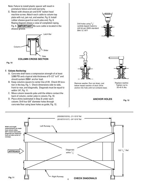
Note: Failure to install plastic spacer will result in<br />
premature failure and void warranty.<br />
G. Retain with sheave pin and 5/16” button head<br />
machine screw. Attach each cable to column top<br />
plate with nut, jam nut, and washer, Fig. 8. Install<br />
rubber sheave guard on each yoke end, Fig. 8.<br />
Roping diagram shows a view of completed roping,<br />
Fig. 9. IMPORTANT Be sure cable is located in the<br />
sheave groove.<br />
Fig. 10<br />
Column<br />
7. Column Anchoring:<br />
A. Concrete shall have a compression strength of at least<br />
3,000 PSI and a typical slab thickness of 5-1/2” to 6” and<br />
should sustain 2000# anchor load.<br />
B. Keep columns square to center line of lift. Check lift loca-<br />
tion in the bay, Fig. 1. Check dimensions side-to-side,<br />
front-to-rear, and diagonally. Diagonals must be equal to<br />
within 1/4", Fig. 11.<br />
C. Move column towards yoke until the sliders contact the<br />
back of column, center yoke in column, Fig. 10.<br />
D. Place shims (estimated in Step 3) under each<br />
column. Drill four 5/8” diameter holes through<br />
concrete floor using base holes as guide, Fig. 13.<br />
Width and length<br />
measurements are made<br />
from column sides,<br />
NOT column base plate.<br />
Diagonals are measured<br />
from out side corner of<br />
runways.<br />
APPROACH<br />
Latch Bar<br />
Slider<br />
Yoke<br />
COLUMN CROSS SECTION<br />
Left Runway<br />
(000/006/010/016) - 211-15/16” Ref.<br />
(001/007/011/017) - 247-15/16” Ref.<br />
Diagonals<br />
within 1 / 4 "<br />
Drill holes using 5 / 8 "<br />
carbide tipped masonry<br />
drill bit per ANSI standard<br />
B94.12.1977<br />
Remove washer. Run nut down, just<br />
below impact section of stud. Drive<br />
anchor into hole until nut contacts base.<br />
Right Runway<br />
Fig. 11<br />
6 CHECK DIAGONALS<br />
ANCHOR HOLES<br />
Replace washer.<br />
Tighten nut to<br />
35-45 ft./lbs.<br />
Fig. 12<br />
122 3 / 16 ” Ref.