ROTARY - SM18 INSTALLATION MANUAL.pdf - Atlantic Auto ...
ROTARY - SM18 INSTALLATION MANUAL.pdf - Atlantic Auto ...
ROTARY - SM18 INSTALLATION MANUAL.pdf - Atlantic Auto ...

You also want an ePaper? Increase the reach of your titles
YUMPU automatically turns print PDFs into web optimized ePapers that Google loves.
K. Use cable ties provided to tie 3/8” air supply to electrical supply<br />
conduit at approximately 2’0” intervals.<br />
14. Bleeding:<br />
Lift must be fully lowered before changing or adding fluid. Raise<br />
and lower lift six times. The cylinder is self-bleeding. After bleeding<br />
system, fluid level in power unit reservoir may be down. Add<br />
more ATF, if necessary, following instructions in Step 12.<br />
To pressure test, run lift to full rise and run motor for approximately<br />
5 seconds. Stop and check all fittings and hose connections.<br />
Tighten or reseal if required. Lower lift. If fill/breather, Fig. 19, is<br />
lost or broken, order replacement.<br />
Note: Some test fluid may be spilled from the cylinder breather<br />
vent during bleeding of the system.<br />
15. Assemble ramp/chocks to rear of runways using hinge pins<br />
and cotter pins, Fig. 26<br />
16. Final Adjustments:<br />
A. Load vehicle such as an RV onto lift.<br />
B. Raise lift to full height. You will hear the locking latch click<br />
through all 12 latch slots.<br />
C. Lower lift onto topmost latch position.<br />
D. Check latch clearance.<br />
1. Starting with the right front column: use a<br />
straight edge to mark the yoke height on the<br />
column, Fig. 27.<br />
2. Raise lift to full height again. Mark second<br />
position. If gap between two marks is<br />
less than 2", adjust locking latch bar to reach<br />
clearance of 2".<br />
a. Adjust locking latch bar adjusting nut so<br />
that the bottom of the topmost latch bar<br />
slot is at least 2" below locking latch,<br />
Fig. 28. After adjustment, tighten jam nut<br />
underneath column top plate, Fig. 28.<br />
b. If entire 2" clearance cannot be attained by<br />
adjusting the locking latch bar, adjust the<br />
cable stud. Loosen cable jam nut, Fig. 27,<br />
and turn adjusting nut to raise the locking<br />
latch 2" above bottom of latch bar slot.<br />
Tighten cable jam nut.<br />
3. Lower lift and remove vehicle.<br />
E. Raise the lift to full height. Listen and watchs the locking<br />
latches click in place. Synchronize the other three columns<br />
with the right front column by adjusting their cables so all four<br />
latches click at same time. Tighten jam nuts.<br />
13<br />
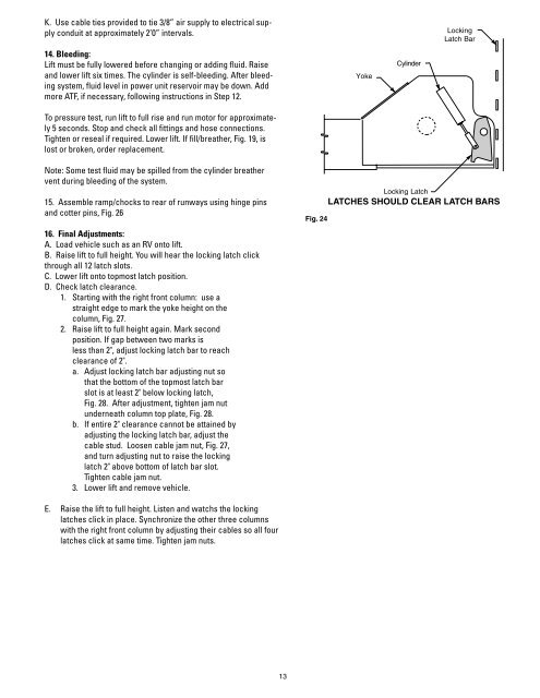
Fig. 24<br />
Yoke<br />
Cylinder<br />
Locking<br />
Latch Bar<br />
Locking Latch<br />
LATCHES SHOULD CLEAR LATCH BARS