AAR-400 Highlights 2002 - Fire Safety Branch - FAA
AAR-400 Highlights 2002 - Fire Safety Branch - FAA
AAR-400 Highlights 2002 - Fire Safety Branch - FAA

You also want an ePaper? Increase the reach of your titles
YUMPU automatically turns print PDFs into web optimized ePapers that Google loves.
Initial<br />
strike<br />
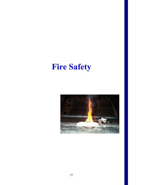
<strong>Fire</strong> <strong>Safety</strong><br />
57
Minimum Performance Standard<br />
for<br />
Halon Replacement Agents for<br />
Aircraft<br />
Cargo Compartment <strong>Fire</strong>s<br />
The<br />
<strong>Fire</strong> <strong>Safety</strong> <strong>Branch</strong>, <strong>AAR</strong>-440, of the<br />
<strong>FAA</strong><br />
William J. Hughes Technical Center<br />
published a technical note titled “Minimum<br />
Performance Standard for Aircraft Cargo<br />
Compartment Halon Replacement <strong>Fire</strong><br />
Suppression<br />
Systems,” DOT/<strong>FAA</strong>/AR-<br />
TN03/6,<br />
Reinhardt, J., April 2003. This<br />
technical<br />
note establishes the minimum<br />
performance standard (MPS) that<br />
a Halon<br />
1301 replacement aircraft cargo<br />
compartment fire suppression system<br />
must<br />
meet.<br />
It describes the tests that shall be<br />
performed<br />
to demonstrate that the<br />
performance<br />
of the replacement agent and<br />
system<br />
provides the same level of safety as<br />
the<br />
currently used Halon 1301 system. This<br />
MPS<br />
was developed in conjunction with the<br />
International<br />
Aircraft Systems <strong>Fire</strong><br />
Protection Working Group, formerly known<br />
as the International Halon Replacement<br />
Working Group. In the past, the aircraft<br />
industry selected Halon 1301 total flood fire<br />
suppression systems as the most effective<br />
means for complying with the <strong>FAA</strong><br />
regulations. Because of the ban on the<br />
production of Halon 1301 due to its harmful<br />
effects to the ozone layer (effective January<br />
1994, as mandated by the Montreal<br />
Protocol), new fire suppression systems will<br />
need to be certified when Halon 1301 is no<br />
longer available.<br />
The<br />
tests described in this standard are one<br />
part<br />
of the total <strong>FAA</strong> and Joint Aviation<br />
Authority<br />
certification process for cargo<br />
compartment fire suppression systems.<br />
Compliance with other applicable<br />
regulations is also required. Supplemental<br />
Type Certificate applicants attempting to<br />
certify replacement systems are encouraged<br />
to discuss the required process with<br />
regulatory agencies prior to conducting tests.<br />
58<br />
The results of these tests will be used to<br />
determine the required concentration levels<br />
to adequately protect an aircraft cargo<br />
compartment against fire and hydrocarbon<br />
explosions. Currently, the <strong>FAA</strong> Transport<br />
Airplane Directorate is developing a policy<br />
letter to address the certification of aircraft<br />
cargo compartment fire suppression systems<br />
employing halon replacement agents and<br />
recommend the use of this standard as part<br />
of the means of compliance.<br />
different MPS fire test<br />
new cargo compartment fire<br />
stems must meet: (1) bulks<br />
A and C fire),<br />
) containerized fire (Class A and C fire),<br />
) flammable liquid fire (Class B fire), and<br />
) an aerosol can explosion (figure 1). The<br />
bulk- and containerized-load fires, which are<br />
deep-seated fire scenarios, use shredded<br />
paper loosely packed in cardboard boxes to<br />
simulate the combustible fire load. The<br />
difference between these two tests is that in<br />
the containerized fire load the boxes are<br />
stacked inside an LD-3 container, while in<br />
the bulk-load fire scenario the boxes are<br />
loaded directly into the cargo compartment.<br />
The flammable liquid test uses 0.5 U.S<br />
gallon (1.89 liters) of Jet A as fuel. The<br />
aerosol explosion tests are executed by using<br />
an aerosol can simulator containing a<br />
flammable and explosive mixture of<br />
propane, alcohol, and water. This mixture<br />
ignites and causes an explosion within an<br />
enclosure when it is exposed to an arc from<br />
sparking electrodes. At least five tests per<br />
MPS scenario must be conducted. These<br />
tests are performed in a 2000 ft 3 There are four<br />
scenarios that<br />
suppression sy<br />
load fire (Clas<br />
(2<br />
(3<br />
(4<br />
simulated<br />
aircraft cargo compartment.<br />
The suppression performance of a new<br />
agent, once the data is collected and<br />
analyzed, is then compared with the<br />
standard acceptance criteria to determine if<br />
acceptance criteria values are based on the it
Figure 1. Example of an MPS Test<br />
Scenario—Aerosol Can Explosion Test<br />
passes or fails the fire tests. The<br />
performance of Halon 1301. It is required<br />
that none of the peak temperatures and areas<br />
Development of an Onboard Inert<br />
Gas Generation System to Prevent<br />
Fuel Tank Explosions<br />
During FY03, significant progress was<br />
made<br />
in the development of a practical and costeffective<br />
inerting system to prevent fuel tank<br />
explosions. An inerting system reduces the<br />
concentration of oxygen in a flammable fuel<br />
mixture to a level that will not support<br />
combustion. Engine bleed air is passed<br />
through an air separation module (ASM),<br />
a<br />
device that separates air into two<br />
streams⎯nitrogen-enriched air (NEA) and<br />
oxygen-enriched air (OEA). A system<br />
developed by the <strong>FAA</strong> inerts the fuel tank<br />
with the NEA generated by the ASM and<br />
discharges the OEA overboard.<br />
The <strong>FAA</strong> was challenged by industry to<br />
develop a practical and reliable system that<br />
could be installed on commercial airliners<br />
within the next several years. Previous<br />
onboard designs, developed and used<br />
by the<br />
military, were relatively heavy and<br />
experienced poor dispatch reliability,<br />
something that could not be tolerated by the<br />
airlines. Ground-based inerting was an<br />
improvement, but required an airport<br />
59<br />
under the time-temperature curves exceed<br />
the values specified in the acceptance<br />
criteria table.<br />
The MPS discussed above replaces the<br />
standard reported in the technical report<br />
titled “Development of a Minimum<br />
Performance Standard for Aircraft Cargo<br />
Compartment Gaseous <strong>Fire</strong> Suppression<br />
Systems,” DOT/<strong>FAA</strong>/AR-00/28, Reinhardt,<br />
J., September 2000. In addition<br />
to gaseous<br />
replacement<br />
agents, the more recent MPS<br />
can be applied to nongaseous agents such<br />
as<br />
water or dry powder.<br />
John Reinhardt, <strong>AAR</strong>-440, (609)<br />
485-5034<br />
infrastructure to supply nitrogen at each gate<br />
and a dedicated technician to transfer the<br />
nitrogen into the fuel tank, all at great<br />
expense. A simple concept was designed by<br />
<strong>FAA</strong> personnel. <strong>Fire</strong> <strong>Safety</strong> <strong>Branch</strong><br />
personnel built a system from that design<br />
and ground tested it at the William J.<br />
Hughes Technical Center. The design<br />
incorporated a clever and relatively simple<br />
dual-flow design for generating NEA in<br />
flight. By using high-purity and low-flow<br />
NEA during ascent and cruise and lower-<br />
purity and high-flow NEA during descent,<br />
analytical modeling showed that most<br />
aircraft and flight regimes would render<br />
the<br />
fuel tank inert upon landing. Moreover,<br />
earlier experiments showed that the fuel tank<br />
would continue to remain inert while the<br />
aircraft was on the ground, negating the<br />
need for labor-intensive and costly ground<br />
operations. Industry was impressed by the<br />
relative simplicity of the design and the<br />
positive modeling results.<br />
The <strong>Fire</strong> <strong>Safety</strong> <strong>Branch</strong> tested a small-scale<br />
fuel tank in a pressure vessel that could<br />
simulate the low pressures corresponding<br />
to<br />
various flight altitudes. The testing showed<br />
that the concentration of oxygen required to<br />
inert against a fuel tank explosion was
higher than previously thought, reducing the<br />
amount of NEA needed to protect the tank,<br />
significantly reducing the size and weight of<br />
the inerting system. In addition, simulated<br />
flight tests in an altitude chamber, initially<br />
on the ASM and later with a 1/4-scale model<br />
of a B747 center wing tank, provided<br />
favorable data that were consistent with the<br />
analytical model predictions. The 1/4-scale<br />
modeling<br />
tests mapped the distribution of<br />
nitrogen (actually measured reduced oxygen<br />
level),<br />
with time, throughout the 6-bay<br />
center<br />
wing tank over entire flight regimes.<br />
The combination of analytical model<br />
predictions, the <strong>Fire</strong> <strong>Safety</strong> <strong>Branch</strong>’s testing<br />
in the altitude chamber, and ground<br />
demonstration tests of the inerting system on<br />
the B747SP was enough to convince Boeing<br />
to pursue onboard inerting as a viable means<br />
of preventing fuel tank explosions.<br />
On December 12, <strong>2002</strong>, a major<br />
press<br />
conference<br />
was held for the national news<br />
and TV media at the <strong>FAA</strong> William J.<br />
Hughes Technical Center to highlight the<br />
recent significant progress in fuel tank<br />
inerting. The press was briefed by Nick<br />
Sabatini, AVR-1, and John Hickey, AIR-1,<br />
on the full scope of the <strong>FAA</strong>’s program to<br />
protect fuel tanks. This was followed by a<br />
number of demonstrations. After viewing<br />
the installation of the inerting system<br />
in the<br />
pack bay area of the B747SP ground test<br />
aircraft, the media witnessed its operation<br />
from an instrumentation room containing a<br />
series of oxygen concentration analyzers<br />
that measure the state of the six center<br />
wing<br />
tank<br />
bays. Also, a small-scale fuel tank<br />
explosion was shown to the press in the<br />
pressure vessel facility, followed by an<br />
inerting test that prevented the explosion.<br />
Lastly, the altitude chamber tests with the<br />
1/4-scale model of the B747 center wing<br />
tank were explained. The newspaper<br />
articles and TV coverage were generally<br />
positive, and Administrator Marion Blakey<br />
characterized the inerting system as a “major<br />
breakthrough.”<br />
60<br />
In July 2003, Boeing began a flight test<br />
program to certify an onboard inert gas<br />
generating system<br />
(OBIGGS), which is<br />
based<br />
on the <strong>FAA</strong> design, on a B747<br />
aircraft. The Boeing flight test program is<br />
being supported with instrumentation (as<br />
described in “A Description and Analysis<br />
of<br />
the <strong>FAA</strong> Onboard Oxygen Analysis<br />
System,” DOT/<strong>FAA</strong>/AR-TN03/52, Mike<br />
Burns and William M. Cavage, July 2003)<br />
and personnel from the <strong>Fire</strong> <strong>Safety</strong> <strong>Branch</strong>.<br />
Boeing publicly announced their intent to<br />
begin installing OBIGGSs on B747 aircraft<br />
in FY05. The <strong>Fire</strong> <strong>Safety</strong> <strong>Branch</strong> also<br />
performed a joint flight<br />
test program with<br />
Airbus. Tests were conducted using a<br />
modified version of the <strong>FAA</strong>’s B747SP<br />
system installed in the cargo bay of an A320<br />
aircraft (figure 1). <strong>Fire</strong> <strong>Safety</strong> <strong>Branch</strong><br />
personnel collected data using the specially<br />
designed instrumentation shown in figure 2.<br />
That data should lead to a greater<br />
understanding of OBIGGS and<br />
improvements in design.<br />
Figure 1. OBIGGS A320 Flight Test<br />
System<br />
Figure 2. <strong>FAA</strong> Fuel Tank Oxygen<br />
Monitoring System for the A320<br />
William M. Cavage, <strong>AAR</strong>-440, (609) 485-<br />
4993
A Model for the Transport of Heat,<br />
Smoke, and Gases During a Cargo<br />
Compartment <strong>Fire</strong><br />
Current regulations require that aircraft<br />
cargo compartment smoke detectors alarm<br />
within 1 minute of the start of a fire and at a<br />
time before the fire has substantially<br />
decreased the structural integrity of the<br />
airplane. Presently, in-flight and ground<br />
tests, which can be costly and time<br />
consuming, are required to demonstrate<br />
compliance with the regulations. A physics<br />
based computational fluid dynamics (CFD)<br />
tool, which couples heat, mass, and<br />
momentum transfer, has been developed to<br />
decrease the time and cost of the<br />
certification process by reducing the total<br />
number<br />
of in-flight and ground experiments.<br />
The model was developed by Sandia<br />
National Laboratories (SNL) with funding<br />
provided by NASA from their Aviation<br />
<strong>Safety</strong> Program. The tool would provide<br />
information on smoke transport in cargo<br />
compartments under various conditions,<br />
therefore allowing optimal certification tests<br />
to be designed.<br />
The CFD-based smoke transport model will<br />
enhance the certification process by<br />
determining worst-case locations for fires,<br />
optimum placement of fire detector sensors<br />
within the cargo compartment, and sensor<br />
alarm levels needed to achieve detection<br />
within the required certification time. The<br />
model is fast-running to allow for simulation<br />
of numerous fire scenarios in a short period<br />
of time. In addition, the model is userfriendly<br />
since it will potentially be used by<br />
airframers and airlines that are not expected<br />
to be experts in CFD. The physics of the<br />
code have been verified by SNL and<br />
validation experiments are ongoing. The<br />
validation experiments are performed at the<br />
<strong>FAA</strong> William J. Hughes Technical Center in<br />
actual aircraft cargo<br />
compartments that are<br />
61<br />
extensively instrumented to record smoke,<br />
temperature, heat flux, and gas species<br />
levels during the tests.<br />
The fire source for the validation tests is a<br />
flaming block of a variety of plastic resin<br />
pellets that are heated and compressed. A<br />
length of nichrome wire is embedded with<br />
the resin block and is used to precisely<br />
control that rate of heat release from the<br />
burning resins. This flaming resin block is<br />
proposed as the standard fire for cargo<br />
compartment fire detection systems and has<br />
been submitted for a patent. Testing has<br />
shown the flaming resin block to be a very<br />
consistent and repeatable fire source. Initial<br />
validation tests show reasonably good<br />
agreement with the code predictions. The<br />
code has been slightly modified to account<br />
for heat transfer to the walls and ceiling of<br />
the cargo compartment, and more validation<br />
experiments are planned. Two technical<br />
reports documenting the results<br />
will be<br />
published next year. One report documents<br />
the properties of the smoke produced by the<br />
flaming resin block compared to the<br />
properties of artificial smoke previously<br />
used in certification tests. The second report<br />
describes the computational approach used<br />
in the code, the graphical user interface that<br />
was developed, and the initial validation test<br />
results.<br />
Figure 1 shows a flaming resin<br />
block, and figure 2 shows the inside of the<br />
B707 cargo compartment used<br />
for a<br />
validation<br />
experiment.<br />
Figure 1. A Flaming<br />
Resin Block
<strong>Fire</strong> and Flammability<br />
Figure 2. The Inside<br />
of a B707<br />
Cargo Compartment<br />
The two stages of fire development are<br />
ignition and growth. If a fire ignites and<br />
grows quickly in an aircraft cabin, there may<br />
not be enough time for passengers to escape.<br />
The <strong>FAA</strong> and other government agencies<br />
have determined that the heat release rate of<br />
burning plastics is the best indicator of how<br />
fast the fire grows in compartments such as<br />
aircraft cabins, trains,<br />
and rooms. However,<br />
none<br />
of the tens of<br />
billions of pounds of<br />
flame-retardant plastic sold worldwide each<br />
year is tested for heat release rate. Instead,<br />
plastics are only tested for ignition<br />
resistance (flammability) by measuring the<br />
time it takes for material to self-extinguish<br />
after removal from a Bunsen burner flame.<br />
Consequently, nothing is known about<br />
whether, or how fast, a fire involving these<br />
plastics will grow to dangerous proportions.<br />
The <strong>Fire</strong> <strong>Safety</strong> <strong>Branch</strong>, <strong>AAR</strong>-440, is<br />
studying the relationship between flame test<br />
performance and fire growth to better<br />
understand the fire hazard of plastics. In<br />
flame tests (figure 1), plastics are not forced<br />
to burn but may continue to do so after<br />
removal of the Bunsen burner if the<br />
sample’s flame returns enough heat to the<br />
62<br />
David Blake, <strong>AAR</strong>-440, (609) 485-4525<br />
plastic surface to sustain the burning<br />
process. In contrast, plastics in fires or fire<br />
calorimeters (figure 2) are exposed to<br />
radiant heat that forces them to burn at a rate<br />
that increases with external heat flux.<br />
Figure 1. Bunsen Burner Test of<br />
Ignition Resistance<br />
Figure 2. <strong>Fire</strong> Calorimetry Test of<br />
Heat Release Rate
<strong>FAA</strong> researchers hypothesized that⎯in the<br />
absence of external heating⎯a plastic will<br />
cease to burn if the rate at which heat is<br />
released by the flame at the tip of the sample<br />
is insufficient to continue the burning<br />
process. To test this hypothesis, the heat<br />
release rate of burning plastics needed to be<br />
measured without any external heating (i.e.,<br />
the unforced heat release rate, HRR0) and<br />
compared to the results of Bunsen burner<br />
tests of ignition resistance. The <strong>FAA</strong> used<br />
two strategies to measure<br />
the unforced heat<br />
release rate of plastics: direct measurement<br />
of HRR0 in an isolated flame test and<br />
obtaining HRR0 as the zero heat flux<br />
intercept in a plot of heat<br />
release rate versus<br />
external heat flux measured, as<br />
shown in<br />
figure<br />
3.<br />
Heat Release Rate, kW/m 2<br />
800<br />
600<br />
<strong>400</strong><br />
200<br />
0<br />
-200<br />
-<strong>400</strong><br />
Plastic A<br />
Plastic B<br />
External Heat Flux, kW/m2<br />
Plastic C<br />
slopes ∝ fire growth<br />
intercepts ∝ ignitability<br />
0 20 40 60 80 100<br />
Figure 3. Typical Plot of Heat Release Rate<br />
Versus External Heat Flux Measured<br />
Typical results for HRR0 obtained by the<br />
extrapolation<br />
method are shown<br />
schematically in figure 3 for three different<br />
plastics. Both the direct and indirect<br />
(intercept) methods gave comparable results<br />
for HRR0. Separate tests were conducted to<br />
measure the ignition resistance of plastics in<br />
a flame test (figure 1) using standard<br />
procedures. Data from dozens of<br />
63<br />
commercial plastics and research materials<br />
were collected and analyzed.<br />
The <strong>FAA</strong> found that plastics will selfextinguish<br />
when removed from a Bunsen<br />
burner flame if their release heat release rate<br />
in unforced flaming combustion HRR0 is<br />
below a critical value of about 100 kW/m<br />
0<br />
clear from figure 4 that<br />
2 .<br />
Figure 4 shows data for flammability rating<br />
in the Underwriters Laboratories Test for<br />
Flammability of lastics (UL 94) versus<br />
HRR for over 40 different plastics. It is<br />
self-extinguishing<br />
0<br />
than about 100 kW/m 2 P<br />
behavior (UL 94 V0 rating) is observed<br />
exclusively for plastics having HRR less<br />
. Thus, both stages of<br />
fire development, ignition and growth,<br />
depend on the heat release rate, a quantity<br />
that is easily measured in a fire calorimeter<br />
(kilogram samples) or in the <strong>FAA</strong>’s<br />
microscale combustion calorimeter<br />
( milligram samples). This result allows fire<br />
protection engineers and <strong>FAA</strong> regulators to<br />
better estimate the fire hazard of a plastic in<br />
a particular environment from a few heat<br />
release rate tests.<br />
UL 94 Rating<br />
HB<br />
V2<br />
V1<br />
V0<br />
Self<br />
Extinguishing<br />
Self<br />
Propagating<br />
-<strong>400</strong> -200 0 200 <strong>400</strong> 600<br />
Unforced Heat Release Rate HRR0, kW/m2<br />
Figure 4. Ignition Resistance Measured in a<br />
Bunsen Burner Flame Test versus Heat<br />
Release Rate Intercept for 40 Plastics<br />
Richard E. Lyon, <strong>AAR</strong>-440, (609) 485-6076
Ground Tests of Aircraft Flight<br />
Deck Smoke Penetration Resistance<br />
A technical note was published titled<br />
“Ground Tests of Aircraft Flight Deck<br />
Smoke Penetration Resistance,”<br />
DOT/<strong>FAA</strong>/AR-TN03/36, Blake, D., in April<br />
2003. The report describes recent testing<br />
performed in support of an Aviation<br />
Rulemaking Advisory Committee<br />
harmonization working group using the <strong>Fire</strong><br />
<strong>Safety</strong> <strong>Branch</strong>’s B747SP and B727 aircraft.<br />
The group was tasked with developing draft<br />
regulations and advisory material to<br />
implement an International Civil Aviation<br />
Organization (IACO) agreement to include<br />
security considerations into the type<br />
certification<br />
of new aircraft.<br />
One of the new requirements of the IACO<br />
agreement was to include specific design<br />
features to prevent smoke and gases from<br />
entering the flight deck following the<br />
activation of an explosive or incendiary<br />
device anywhere in the aircraft except the<br />
flight deck itself. The threat from this<br />
scenario would be the smoke and gases from<br />
the ensuing fire. Ground tests were<br />
conducted in both aircraft to either measure<br />
or demonstrate the positive pressure<br />
differential between the flight deck and<br />
surrounding areas needed to prevent smoke<br />
penetration<br />
into the flight deck. Bleed air<br />
from the aircraft’s auxiliary power unit was<br />
used to run the air-conditioner packs, and<br />
every<br />
possible combination of each<br />
aircraft’s ventilation system settings was<br />
tested. An actual pressure differential<br />
was<br />
not directly measurable using a differential<br />
pressure gauge (figure 1) with a resolution<br />
of 0.005 inch of water (0.00018 psi) at any<br />
ventilation system configuration in either<br />
aircraft.<br />
64<br />
Figure 1. Differential Pressure Gauge<br />
To test the positive and negative pressure<br />
differential, a thin sheet of plastic covering<br />
was installed over the flight deck door<br />
opening (figure 2). Enough plastic was used<br />
to allow the plastic sheet to deflect either<br />
forward or aft based on the airflow direction.<br />
When airflow into the flight deck of the<br />
B727 was maximized and the cabin airflow<br />
was minimized, the plastic sheet clearly<br />
deflected into the cabin area, indicating a<br />
positive flight deck pressure differential.<br />
Figure 2. Plastic Sheet Installed Over the<br />
Flight Deck Door Opening
A theatrical smoke generator was then used<br />
to determine if this positive flight deck<br />
pressure<br />
differential was sufficient to<br />
prevent smoke penetration. The smoke<br />
generator was placed in the cabin of the<br />
B727 with the output nozzle pointing at the<br />
closed flight deck door approximately<br />
8 feet<br />
away. The generator was turned on at its<br />
maximum output, completely filling the<br />
forward cabin section of the B727 with<br />
smoke. No smoke penetrated into the flight<br />
deck for this ventilation condition. These<br />
tests were repeated at every other ventilation<br />
system setting that did not cause the plastic<br />
sheet to deflect into the cabin area, and<br />
smoke penetrated into the flight deck in<br />
every case. Similar tests were conducted in<br />
the B747SP aircraft. None of the ventilation<br />
settings caused a deflection of the plastic<br />
<strong>FAA</strong> Adopts Final Rule Requiring<br />
Improved <strong>Fire</strong> Tests for Thermal<br />
Acoustic Insulation<br />
The <strong>FAA</strong> adopted improved and new<br />
flammability test standards for thermal<br />
acoustic insulation used in transport<br />
airplanes (see Federal Register, July 31,<br />
2003, pp. 45046 to 45084). The standards<br />
include new flammability tests for in-flight<br />
fire ignition resistance and postcrash fire<br />
burnthrough resistance. Both test methods<br />
were developed by the <strong>Fire</strong> <strong>Safety</strong> <strong>Branch</strong>,<br />
<strong>AAR</strong>-440. Earlier fire tests and aircraft<br />
service experience had shown that the<br />
current standards did not adequately address<br />
situations in which current insulation<br />
materials contributed to the propagation of a<br />
fire. The new rule will improve aircraft<br />
safety “by reducing the incidence and<br />
severity of cabin fires, particularly those in<br />
inaccessible areas where thermal acoustic<br />
insulation is installed, and providing<br />
additional<br />
time for evacuation by delaying<br />
the entry of postcrash fires into the cabin”<br />
(Federal Register, July 31, 2003, p. 45046).<br />
65<br />
sheet into the cabin area in this aircraft, and<br />
smoke penetrated into the flight deck in<br />
every test regardless of the ventilation<br />
system settings.<br />
The technique of using a plastic sheet to<br />
demonstrate the existence of a positive<br />
pressure differential and theatrical smoke<br />
generators to demonstrate the effectiveness<br />
of that pressure differential will be described<br />
in a new advisory circular as an acceptable<br />
method<br />
for complying with new regulations.<br />
The availability of functional test aircraft<br />
greatly enhances the <strong>Fire</strong> <strong>Safety</strong> <strong>Branch</strong>’s<br />
ability to provide timely and realistic test<br />
results for <strong>FAA</strong> regulatory support.<br />
Dave Blake, <strong>AAR</strong>-440, (609) 485-4525<br />
The new test method for in-flight fire<br />
resistance is called the radiant panel test<br />
since<br />
it subjects a material heated by a<br />
radiant<br />
panel to a pilot flame (see figure 1).<br />
It gave a good correlation with large-scale<br />
fire test data. The pass/fail criteria require<br />
that any flaming not extend beyond a 2-inch<br />
length from the point of flame application or<br />
continue flaming after removal of the pilot<br />
flame. Most insulation cover materials that<br />
are currently in use, which are thin films,<br />
will not meet the new fire test criteria. For<br />
example, based on past tests, most Mylar<br />
films, particularly the metallized types, fail<br />
the test, as do many of the Tedlars. Kapton<br />
films are good performers, as was one<br />
metallized Tedlar, and would be compliant<br />
with the new criteria. However, other<br />
factors affect the flammability of the<br />
insulation film materials, including weight<br />
or<br />
thickness, scrim (reinforcing lattice) type<br />
and<br />
pitch, scrim adhesive, and use of flame<br />
retardants. Thus, it is expected that new<br />
film<br />
formulations will be developed now<br />
that the rule has been adopted.
Figure 1. Schematic of Radiant Panel Test<br />
Apparatus<br />
The test method for postcrash fire<br />
burnthrough resistance is a new test<br />
requirement since fuselage burnthrough<br />
resistance was not explicitly addressed in<br />
previous <strong>FAA</strong> regulations. It is comprised<br />
of two main components: a large burner that<br />
simulates a jet fuel fire and a sample holder<br />
representative of the fuselage structural<br />
framing (see figure 2).<br />
Figure 2. Proposed Burnthrough Test<br />
Apparatus<br />
The burner flame conditions were set so that<br />
the melting time of aluminum sheeting<br />
would coincide with full-scale test results.<br />
66<br />
By analyzing past accidents, the required<br />
pass/fail criteria for the insulation specimen<br />
were set at 4 minutes because there would<br />
be very limited benefit<br />
beyond this period<br />
(i.e.,<br />
approximately 5 minutes, factoring in<br />
the skin melting time). The burnthrough<br />
time is based on visual observation and<br />
measured heat flux through the specimen<br />
back face. The <strong>FAA</strong> has tested numerous<br />
samples submitted by industry, and many<br />
have passed the required criteria. Compliant<br />
specimens fall into three broad categories:<br />
advanced fibrous material (fiberglass<br />
replacement), fire barrier with existing<br />
fiberglass, and hardened film material.<br />
Work<br />
is near completion for a planned<br />
advisory circular to support implementation<br />
of the new flammability requirements for<br />
thermal<br />
acoustic insulation. A standardized<br />
radiant panel test methodology is being<br />
finalized for the evaluation of tape and hook<br />
and loop (Velcro). Both are used<br />
extensively in the installation of insulation<br />
blankets, and torn blankets are repaired with<br />
tape. It has been found that both<br />
components can contribute significantly to<br />
insulation blanket flammability. In addition,<br />
the method of installing the blanket onto the<br />
fuselage framing has a critical effect on the<br />
degree of burnthrough resistance. Insulation<br />
blanket overlapping and using proper<br />
fasteners are required to gain full potential<br />
burnthrough protection. Factors affecting<br />
the effectiveness of fasteners (fixing<br />
methods) include composition (metal or<br />
plastic), through-insulation pins versus<br />
clamps, the pitch or spacing of the fasteners,<br />
and the proper attachment to a stringer or<br />
former.<br />
Gus Sarkos, <strong>AAR</strong>-440, (609) 485-5620