Application Note #5425 - Galil
Application Note #5425 - Galil
Application Note #5425 - Galil

Create successful ePaper yourself
Turn your PDF publications into a flip-book with our unique Google optimized e-Paper software.
<strong>Application</strong> <strong>Note</strong> <strong>#5425</strong><br />
Connecting a Gemini GV Amplifier to a <strong>Galil</strong> Controller<br />
This application note describes the procedure for properly connecting and tuning a<br />
Compumotor (a division of Parker Automation) Gemini GV amplifier using a <strong>Galil</strong><br />
DMC-1800 controller and an ICM-1900 interconnect module. While this document is<br />
specific to the DMC-1800, the approach taken can be used as a reference for any<br />
OPTIMA series controller.<br />
Components referred to in this document include:<br />
• <strong>Galil</strong> DMC-1800 controller<br />
• <strong>Galil</strong> ICM-1900 interconnect module<br />
• <strong>Galil</strong> WSDK servo tuning software<br />
• Compumotor Gemini GV-U6E amplifier<br />
• Compumotor brushless servo motor – model N0342FE<br />
• Compumotor “Motion Planner” software – version 2.9<br />
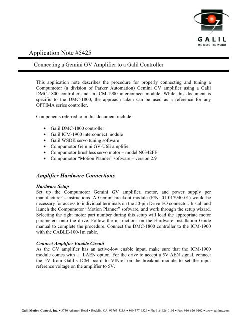
Amplifier Hardware Connections<br />
Hardware Setup<br />
Set up the Compumotor Gemini GV amplifier, motor, and power supply per<br />
manufacturer’s instructions. A Gemini breakout module (P/N: 01-017940-01) would be<br />
necessary for access to individual terminals on the 50-pin Drive I/O connector. Install and<br />
launch the Compumotor “Motion Planner” software, and work through the setup wizard.<br />
Selecting the right motor part number during this setup will load the appropriate motor<br />
parameters onto the drive. Follow the instructions on the Hardware Installation Guide<br />
manual to complete the procedure. Connect the DMC-1800 controller to the ICM-1900<br />
with the CABLE-100-1m cable.<br />
Connect Amplifier Enable Circuit<br />
As the GV amplifier has an active-low enable input, make sure that the ICM-1900<br />
module comes with a –LAEN option. For the drive to accept a 5V AEN signal, connect<br />
the 5V from <strong>Galil</strong>’s ICM board to VINref on the breakout module to set the input<br />
reference voltage on the amplifier to 5V.<br />
<strong>Galil</strong> Motion Control, Inc. • 3750 Atherton Road • Rocklin, CA 95765 USA • 800-377-6329 • Ph: 916-626-0101 • Fax: 916-626-0102 • www.galilmc.com
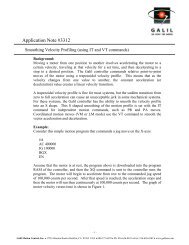
Connect Encoder Signal<br />
The quadrature encoder signals are connected to the ICM-1900 from the corresponding<br />
pins (14-19) on the Gemini breakout module. The following diagram (see Fig. 1)<br />
describes the proper connections for an x-axis system.<br />
<strong>Note</strong>: Encoder signal connection is optional when operating in position mode.<br />
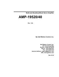
Connect Analog Motor Command Signal<br />
Connect MOCMD(x) ±10v analog motor command signal to Cmd+ on the Compumotor<br />
amplifier for operations in the torque or velocity modes. Connection to the Cmd- would<br />
not be necessary, since our command signal is single-ended. For ground reference,<br />
connect GND on the ICM to the Analog Ground on the Compumotor amplifier. For<br />
connections in the position mode, go through the steps described in the <strong>Galil</strong> user manual<br />
for connecting stepper motors (see chapter 2). Connections for position mode can be seen<br />
in figure 2.<br />
Compumotor<br />
GV Amplifier<br />
Drive I/O Motor Feedback<br />
Analog Ground (pin 25)<br />
+/- 10V Cmd- (no connect)<br />
+/- 10V Cmd+ (pin 23)<br />
Enable (pin 1)<br />
EN. OUT A+ (pin 14)<br />
EN. OUT A- (pin 15)<br />
EN. OUT B+ (pin 16)<br />
EN. OUT B- (pin 17)<br />
EN. OUT Z+ (pin 18)<br />
EN. OUT Z- (pin 19)<br />
GND (pin 17)<br />
MOCMDX (pin 32)<br />
AMPENX (pin 40)<br />
<strong>Galil</strong><br />
ICM-1900 - LAEN<br />
VINref (pin 26) +5V (pin 36)<br />
To N0342FE<br />
Brushless<br />
Servo Motor<br />
+MAX (pin 83)<br />
-MAX (pin 84)<br />
+MBX (pin 85)<br />
-MBX (pin 86)<br />
+INX (pin 87)<br />
-INX (pin 88)<br />
Figure 1: Basic hardware connections for torque / velocity modes<br />
<strong>Galil</strong> Motion Control, Inc. • 3750 Atherton Road • Rocklin, CA 95765 USA • 800-377-6329 • Ph: 916-626-0101 • Fax: 916-626-0102 • www.galilmc.com
Compumotor<br />
GV Amplifier<br />
Drive I/O Motor Feedback<br />
Digital Ground (pin 6 or 7)<br />
Dir+ (pin 10)<br />
Step+ (pin 8)<br />
Enable (pin 1)<br />
EN. OUT A+ (pin 14)<br />
EN. OUT A- (pin 15)<br />
EN. OUT B+ (pin 16)<br />
EN. OUT B- (pin 17)<br />
EN. OUT Z+ (pin 18)<br />
EN. OUT Z- (pin 19)<br />
GND (pin 17)<br />
PWMX (pin 34)<br />
AMPENX (pin 40)<br />
<strong>Galil</strong><br />
ICM-1900 - LAEN<br />
VINref (pin 26) +5V (pin 36)<br />
To N0342FE<br />
Brushless<br />
Servo Motor<br />
SIGNX (pin 33)<br />
optional<br />
Figure 2: Basic hardware connections for position mode<br />
Performance <strong>Note</strong>s<br />
+MAX (pin 83)<br />
-MAX (pin 84)<br />
+MBX (pin 85)<br />
-MBX (pin 86)<br />
+INX (pin 87)<br />
-INX (pin 88)<br />
The following notes are written to explain the tuning procedures when the Gemini<br />
amplifier is in the torque and velocity modes. The DMODE command sets the operational<br />
mode in the Motion Planner software. Since the position mode is operated under an open<br />
loop condition, no tuning of the controller is required in this mode.<br />
<strong>Note</strong>: The planetary gear-head on the N0342FE motor was removed during this tuning<br />
analysis in order to achieve a more conclusive characterization of the motor.<br />
Torque Mode<br />
When set to torque mode (DMODE2), the Gemini GV has no internal control loop, thus<br />
tuning is only done through the <strong>Galil</strong> controller using our WSDK software. However,<br />
advanced adjustments to the Gemini GV drive in this mode can be made; a section called<br />
‘Torque Mode Tuning Procedure’ can be found on the Gemini’s hardware installation<br />
guide. Best tuning results seem to come from the Auto Crossover Frequency test, but due<br />
to the high torque-density packaging of the motor, system response may be unrepeatable.<br />
<strong>Galil</strong> Motion Control, Inc. • 3750 Atherton Road • Rocklin, CA 95765 USA • 800-377-6329 • Ph: 916-626-0101 • Fax: 916-626-0102 • www.galilmc.com
To further improve on the step response attained during the Auto Crossover test, switch<br />
to the Manual Tuning method and begin fine-tuning by changing the KD and KP values<br />
to achieve a minimal overshoot and quick settling time for the step response. Then, adjust<br />
KI for positional accuracy. Decreasing the controller’s update time (500μsec minimum)<br />
causes the Auto Crossover test to yield higher PID values. If instability starts occurring<br />
due to the higher control filter (seen as high frequency oscillations in the step response),<br />
proceed to the manual tuning method and decrease the PID values until the step response<br />
becomes more stable.<br />
Velocity Mode<br />
When set to velocity mode (DMODE4), the Gemini amplifier has three basic tuning<br />
parameters that can be adjusted. They are DVBW, SGVRAT and SGINTE (refer to your<br />
Gemini command reference set). However, each motor model has its own set of default<br />
parameters, which can be loaded onto the amplifier if the correct motor model number is<br />
selected in the setup wizard. Therefore, extensive tuning to adjust these three parameters<br />
is not necessary. During a test where the controller’s PID is set to zero, an open-loop<br />
voltage step input is fed to the amplifier, and the actual velocity plotted – setting DVBW<br />
value to 70 (default is 50) seems to improve the motor’s response considerably.<br />
SGVRAT1 and SGINTE1 default values remain. Once again, due to the high torquedensity<br />
packaging of the motor, the Auto Crossover Frequency test, which involves pulse<br />
inputs to the drive, does not work well in the velocity mode. This holds true even when<br />
the pulse magnitude in the Edit/Crossover Tuning Parameters is set to 0.5V. The digital<br />
‘smart’ drive expects the motor to be at a certain velocity with each given pulse input<br />
instantly, but high friction in the motor makes it impossible. To close up on this velocity,<br />
the drive would falsely put in an increased voltage, which results in extreme instability on<br />
the motor. The best tuning method for this mode is the Point-to-Point test, which gives a<br />
settling time of 4ms and a maximum overshoot of 25 counts during a 1000-count move.<br />
<strong>Note</strong>: In the event that a tuning method dose not work properly, go to the Edit menu and<br />
try changing the tuning parameters to more closely resemble the actual environment in<br />
which the motor is going to be operating. Contact an application engineer at <strong>Galil</strong> for<br />
assistance in tuning the <strong>Galil</strong> filter.<br />
<strong>Galil</strong> Motion Control, Inc. • 3750 Atherton Road • Rocklin, CA 95765 USA • 800-377-6329 • Ph: 916-626-0101 • Fax: 916-626-0102 • www.galilmc.com