Owner's manual - Tehnoturg
Owner's manual - Tehnoturg
Owner's manual - Tehnoturg

You also want an ePaper? Increase the reach of your titles
YUMPU automatically turns print PDFs into web optimized ePapers that Google loves.
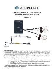
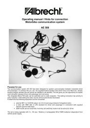
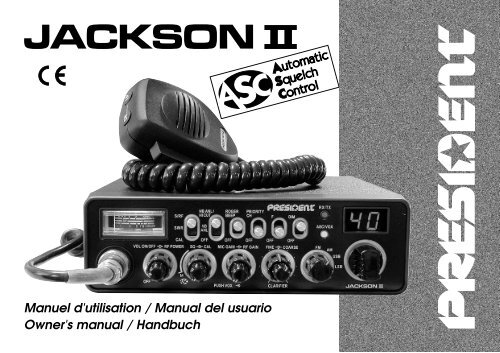
Manuel d'utilisation / Manual del usuario<br />
<strong>Owner's</strong> <strong>manual</strong> / Handbuch
Votre PRESIDENT JACKSON II ASC en un coup d'œil Un vistazo a vuestro PRESIDENT JACKSON II ASC<br />
Your PRESIDENT JACKSON II ASC at a glance<br />
Ihr PRESIDENT JACKSON II ASC auf einen Blick
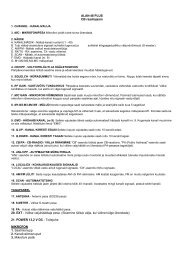
SOMMAIRE<br />
INSTALLATION 5<br />
UTILISATION 7<br />
CARACTÉRISTIQUES TECHNIQUES 10<br />
GUIDE DE DÉPANNAGE 11<br />
COMMENT ÉMETTRE/RECEVOIR UN MESSAGE 11<br />
GLOSSAIRE 11<br />
DÉCLARATION DE CONFORMITÉ 13<br />
GARANTIE 14<br />
TABLEAUX DES FRÉQUENCES 47~ 49<br />
TABLEAU DES NORMES EUROPÉENNES 50<br />
SUMMARY<br />
INSTALLATION 29<br />
HOW TO USE YOUR CB 31<br />
TECHNICAL CHARACTERISTICS 34<br />
TROUBLE SHOOTING 35<br />
HOW TO TRANSMIT OR RECEIVE A MESSAGE 35<br />
GLOSSARY 35<br />
CERTIFICATE OF CONFORMITY 37<br />
FREQUENCY TABLES 47~ 49<br />
EUROPEAN NORMS 50<br />
Français<br />
English<br />
3<br />
SUMARIO<br />
INSTALACIÓN 17<br />
UTILIZACIÓN 19<br />
CARACTERÍSTICAS TÉCNICAS 22<br />
GUÍA DE PROBLEMAS 23<br />
COMO EMITIR O RECIBIR UN MENSAJE 23<br />
LÉXICO 23<br />
DECLARACIÓN CE DE CONFORMIDAD 25<br />
GARANTÍA 26<br />
TABLAS DE FRECUENCIAS 47~ 49<br />
NORMAS EUROPEAS 50<br />
INHALTSANGABE<br />
Español<br />
Deutsch<br />
INSTALLATION 39<br />
BEDIENUNG 41<br />
TECHNISCHE DATEN 44<br />
BEI PROBLEMEN 45<br />
TIPS FÜR DEN FUNKVERKEHR 45<br />
BEURTEILUNG DER EMPFANGSQUALITÄT 45<br />
KONFORMITÄTSERKLÄRUNG 37<br />
CB-KANÄLE UND IHRE FREQUENZEN 47 ~ 49<br />
EUROPÄISCH NORMEN 50
Welcome to the world of the new generation of CB<br />
radios. The new PRESIDENT range gives you access to<br />
top performance CB equipment. With the use of up-todate<br />
technology, which guarantees unprecedented<br />
quality, your PRESIDENT JACKSON II ASC is a new step in<br />
personal communication and is the surest choice for the<br />
most demanding of professional CB radio users. To ensure<br />
that you make the most of all its capacities, we<br />
advise you to read carefully this <strong>manual</strong> before installing<br />
and using your PRESIDENT JACKSON II ASC.<br />
A) INSTALLATION<br />
1) WHERE AND HOW TO MOUNT YOUR MOBILE CB RADIO<br />
a) You should choose the most appropriate setting from a simple and practical<br />
point of view.<br />
b) Your CB radio should not interfere with the driver or the passengers.<br />
MOUNTING DIAGRAM<br />
29<br />
c) Remember to provide for the passing and protection of different wires (e.g.<br />
power, antenna, accessory cabling) so that they do not in any way interfere<br />
with the driving of the vehicle.<br />
d) To install your equipment, use the cradle (1) and the self-tapping screws [2]<br />
provided (drilling diameter 3.2 mm). Take care not to damage the vehicle’s<br />
electrical system while drilling the dash board.<br />
e) Do not forget to insert the rubber joints [3] between the CB and its support as<br />
these have a shock-absorbing effect which permits gentle orientation and<br />
tightening of the set.<br />
f) Choose where to place the microphone support and remember that the<br />
microphone cord must stretch to the driver without interfering with the controls<br />
of the vehicle.<br />
- N.B. : As the transceiver has a frontal microphone socket, it can be set into the<br />
dash board. In this case, you will need to add an external loud speaker to<br />
improve the sound quality of communications (connector EXT.SP situated on<br />
the back panel: C). Ask your dealer for advice on mounting your CB radio.<br />
English
English<br />
2) ANTENNA INSTALLATION<br />
a) Choosing your antenna:<br />
- For CB radios, the longer the antenna, the better its results. Your<br />
be able to help you with your choice of antenna.<br />
dealer will<br />
b) Mobile antenna:<br />
- Must be fixed to the vehicle where there is a maximum of metallic surface<br />
(ground plane), away from windscreen mountings.<br />
- If you already have a radio-telephone antenna installed, the CB antenna<br />
should be higher than this.<br />
- There are two types of antenna: pre-regulated which should be used on a<br />
good ground plane (e.g. car roof or lid of the boot), and adjustable which<br />
offer a much larger range and can be used on a smaller ground plane (see<br />
p. 31 § 5, Adjustment of SWR).<br />
- For an antenna which must be fixed by drilling, you will need a good contact<br />
between the antenna and the ground plane. To obtain this, you should lightly<br />
scratch the surface where the screw and tightening star are to be placed.<br />
- Be careful not to pinch or flatten the coaxial cable (as this runs the risk of break<br />
down and/or short circuiting).<br />
- Connect the antenna (B).<br />
c) Fixed antenna:<br />
- A fixed antenna should be installed in a clear a space as possible. If it is fixed<br />
to a mast, it will perhaps be necessary to stay it, according to the laws in force<br />
(you should seek professional advice). All PRESIDENT antennas and accessories<br />
are designed to give maximum efficiency to each CB radio within the<br />
range.<br />
OUTPUT RADIUS PATTERNS<br />
30<br />
3) POWER CONNECTION<br />
Your PRESIDENT JACKSON II ASC is protected against an inversion of polarities.<br />
However, before switching it on, you are advised to check all the connections.<br />
Your equipment must be supplied with a continued current of 12 volts<br />
(A). Today, most cars and lorries are negative earth. You can check this by<br />
making sure that the negative terminal of the battery is connected either to<br />
the engine block or to the chassis. If this is not the case, you should consult your<br />
dealer.<br />
WARNING: Lorries generally have two batteries and an electrical installation<br />
of 24 volts, in which case it will be necessary to insert a 24/12 volt converter<br />
(type CV 24/12 PRESIDENT) into the electrical circuit. The following connection<br />
steps should be carried out with the power cable disconnected from the set.<br />
a) Check that the battery is of 12 volts.<br />
b) Locate the positive and negative terminals of the battery (+ is red and - is<br />
black). Should it be necessary to lengthen the power cable, you should use<br />
the same or a superior type of cable.<br />
c) It is necessary to connect your CB to a permanent (+) and (-). We advise you<br />
to connect the power cable directly to the battery (as the connection of the<br />
CB cable to the wiring of the car-radio or other parts of the electrical circuit<br />
may, in somecases, increase the likelihood of interference).<br />
d) Connect the red wire (+) to the positive terminal of the battery and the black<br />
(-) wire to the negative terminal of the battery.<br />
e) Connect the power cable to your CB radio.<br />
WARNING: Never replace the original fuse (6 A) by one of a different value.<br />
Zum<br />
starter<br />
Towards<br />
starter<br />
Zum<br />
chassis<br />
Connected<br />
to chassis
4) BASIC OPERATIONS TO BE CARRIED OUT BEFORE USING<br />
YOUR SET FOR THE FIRST TIME (without transmitting and<br />
without using the «push-to-talk» switch on the microphone)<br />
a) Connect the microphone<br />
b) Check the antenna connections<br />
c) Turn the set on by turning the volume knob (1) clockwise.<br />
d) Turn the squelch knob (2) to minimum (M position).<br />
e) Adjust the volume to a comfortable level.<br />
f) Go to Channel 20 using either the «UP» «DN» key on the microphone or the<br />
rotary knob.<br />
5) ADJUSTMENT OF SWR (Standing wave ratio)<br />
WARNING: This must be carried out when you use your CB radio for the first time<br />
(and whenever you re-position your antenna). The adjustment must be<br />
carried out in an obstacle-free area.<br />
* Adjustment with a built-in SWR meter or external SWR meter (e.g. TOS-1 or<br />
TOS-2 President)<br />
a) To connect the SWR meter :<br />
- Connect the SWR meter between the CB radio and the antenna as close as<br />
possible to the CB (use a maximum of 40 cm cable, type President CA 2C).<br />
b) To adjust the SWR meter:<br />
- Set the CB to channel 20 in FM.<br />
- Put the switch on the SWR meter to position CAL or FWD.<br />
- Press the «push-to-talk» switch on the microphone to transmit.<br />
- Bring the index needle to by using the calibration key.<br />
- Change the switch to position SWR (reading of the SWR level). The reading on<br />
the Meter should be as near as possible to 1. If this is not the case, re-adjust your<br />
antenna to obtain a reading as close as possible to 1. (An SWR reading<br />
between 1 and 1.8 is acceptable).<br />
- It will be necessary to re-calibrate the SWR meter after each adjustment of the<br />
antenna.<br />
WARNING: In order to avoid any losses and attenuations in cables used for<br />
connection between the radio and its accessories, PRESIDENT recommends<br />
to use a cable with a length inferior to 3m.<br />
Your CB is now ready for use.<br />
31<br />
B) HOW TO USE YOUR CB<br />
1) ON/OFF - VOLUME ~ RF POWER<br />
ON/OFF - VOLUME<br />
a) To turn the set on, turn the knob (1) clockwise.<br />
b) To increase the sound level, turn the same knob further clockwise.<br />
RF POWER<br />
Adjustment of the output power in AM and FM mode only. Allows reducing the<br />
power in case of a nearby communication with a person who has no RF GAIN.<br />
The normal position of this function is set to maximum, fully clockwise.<br />
2) ASC (Automatic Squelch Control) SQUELCH ~ CAL<br />
SQUELCH<br />
Suppresses undesirable background noises when there is no communication.<br />
Squelch does not affect neither sound nor transmission power, but allows a<br />
considerable improvement in listening comfort.<br />
a) ASC: Automatic Squelch Control<br />
Worldwide patent, a PRESIDENT exclusivity.<br />
Turn the squelch knob (2) anti-clockwise into ASC position. The «ASC/VOX» led<br />
lights up into green.<br />
Note: If the VOX function is also active, the led lights up into orange.<br />
No repetitive <strong>manual</strong> adjustment and a permanent improvement in listening<br />
comfort when ASC is active. This function can be disconnected by turning the<br />
switch clockwise. In this case the <strong>manual</strong> squelch control becomes active<br />
again. The «ASC/VOX» led turns off.<br />
b) MANUAL SQUELCH<br />
Turn the squelch knob clockwise to the exact point where all background<br />
noise disappears. This adjustment should be done with precision as, if set to<br />
maximum (fully clockwise) only the strongest signals will be received.<br />
CAL<br />
Allows the calibration of the SWR meter (see § 5 ADJUSTMENT OF SWR).<br />
English
English<br />
3) MIC GAIN ~ RF GAIN ~ VOX<br />
MIC GAIN<br />
Adjustment of the sensitivity level of the microphone.<br />
The normal position of this function is set to maximum clockwise.<br />
RF GAIN<br />
This knob is for adjusting sensitivity during reception. For long distance communications<br />
RF GAIN should be set to maximum. RF GAIN can be reduced to<br />
avoid distortion, when your correspondent is close by and when he does not<br />
have RF POWER.<br />
The normal setting of this function is on maximum (fully clockwise).<br />
VOX<br />
The VOX function allows transmitting by speaking into the original microphone<br />
(or in the optional vox microphone) without pressing the PTT switch. In case of<br />
the use of an optional vox mike connected to the rear panel of the radio (VOX<br />
MIC jack), the original microphone doesn’t work.<br />
a) VOX Mode<br />
Press shortly the «VOX» key in order to activate the VOX function. The red<br />
«ASC/VOX» led lights up. A new pressure on the «VOX» key switches the<br />
function off. The «ASC/VOX» led turns off.<br />
Note: If the ASC function is also active, the led turns up into orange.<br />
b) VOX adjustment<br />
Press during 1 second the «VOX» key in order to activate the function.<br />
Vox adjustment. Three adjustments are possible: Sensitivity, Anti-Vox level/Vox<br />
delay time. The preset adjustment is the Sensitivity adjustment. Press shortly the<br />
«VOX» key in order to go to the following adjustment. The display shows the<br />
type of adjustment by its first digit and its level by the second digit.<br />
- Sensitivity «L5»: allows the adjustment of the microphone (original one or<br />
optional vox) for an optimum transmission quality. Adjustable level from 1<br />
(high level) to 9 (low level) by rotating the channel knob or with the UP/DN keys<br />
of the original microphone. L corresponds to the Sensitivity (Level).<br />
- Anti-Vox «A0»: allows disabling the transmission generated by the surrounding<br />
noise. The level is adjustable from 0 (Off) to 9 (low level) by rotating the channel<br />
knob or with the UP/DN keys of the original microphone. A corresponds to Anti-<br />
Vox.<br />
- Delay Time « 5»: allows avoiding the sudden cut of the transmission by adding<br />
a delay at the end of speaking. The level is adjustable from 1 (short delay) to<br />
9 (long delay) by rotating the channel selector or with the UP/DN keys of the<br />
32<br />
original microphone. corresponds to delay time.<br />
Once the adjustments are done, press during 1 second the «VOX» key in order<br />
to quit the Vox Adjustment Mode.<br />
4) CLARIFIER<br />
FINE: This function allows a frequency deviation during LSB/USB reception in<br />
order to improve the clearness of your correspondent’s voice.<br />
COARSE: This function allows a frequency deviation in reception.<br />
The normal setting of this function is on the central position.<br />
5) FM / AM / USB / LSB MODE SELECTOR<br />
This switch allows selecting the modulation mode AM, FM, LSB or USB; Your<br />
modulation mode has to correspond to the one of your correspondent.<br />
Frequency Modulation /FM: for nearby communications on a flat open field.<br />
Amplitude Modulation / AM: communication on a field with relief and obstacles<br />
at middle distance (the most used).<br />
Upper and Lower Side Band / USB-LSB: used for long distance communications<br />
(according to the propagation conditions).<br />
6) CHANNEL SELECTOR: knob and UP/DN keys of the microphone<br />
These switches allow increasing or decreasing a channel number. A «Beep»<br />
sounds each time the channel changes if the Beep function is activated (see<br />
Beep Function hereunder).<br />
BEEP FUNCTION<br />
Keys, changing the channel etc.<br />
For activating the Beep: switch on the radio by pressing the UP key of the<br />
microphone<br />
For disabling the Beep: switch on the radio by pressing the DN key of the<br />
microphone<br />
SCAN FUNCTION<br />
In order to activate the SCAN function (research of the channels) in an<br />
increasing way, press the UP key during 2,5 seconds. The scanning automatically<br />
starts 3 seconds after the end of the transmission if no key is activated.<br />
The scanning starts again in an increasing way by using the UP key of the<br />
microphone or in a decreasing way with the DN key of the mike.
7) DISPLAY<br />
The digital LED display shows the channel, its<br />
configuration and the level of some adjustments.<br />
8) ASC/VOX LED<br />
This led is green when the ASC function is active and red when the VOX<br />
function is active. It’s orange when both functions are active.<br />
9) RX/TX LED<br />
This led is red in transmission and green when a signal is received.<br />
10) DIM<br />
The DIMMER function allows adjusting the brightness of the lighting.<br />
11) F<br />
Selection of the frequency bands (configuration :E; d; EU; EC; U; PL)<br />
The frequency bands have to be chosen according with the country of use.<br />
Don’t use another configuration. Some countries need a user’s licence. See<br />
the configurations / frequency bands table at page 47~49.<br />
Proceeding: - switch off the transceiver. Put the switch on «F» position and<br />
switch on again. The letter corresponds to the blinking configuration.<br />
- In order to change the configuration, use the channel selector on the front<br />
panel or the UP/DN keys of the microphone.<br />
- When the configuration is selected, put the switch on «OFF». The letter that<br />
corresponds to the configuration are continuously displayed. At this point,<br />
confirm the selection by switching off the transceiver and then switching it on<br />
again.<br />
See table page 50.<br />
12) PRIORITARY CHANNEL<br />
This switch selects channel 9 or 19 according to the configuration.<br />
See table page 50.<br />
13) ROGER BEEP<br />
The Roger beep sounds while releasing the microphone key in order to let your<br />
correspondent speak. Historically, CB is a mode of «simplex» communication.<br />
This means that it is not possible to speak and to listen at the same time (as it<br />
33<br />
is the case with a telephone). Once someone had finished to talk, he said {<br />
"Roger" in order to prevent his correspondent that it was his turn to talk. "Roger"<br />
has been replaced by a beep. There comes «Roger beep» from.<br />
Note: the «Roger Beep» also sounds in the loudspeaker if the function is<br />
already active while switching on the transceiver. If the function is on OFF while<br />
switching on the radio, only the correspondent can hear the «Roger Beep».<br />
14) NB.ANL / HI-CUT<br />
3 positions switch: Off / NB.ANL filter activated / NB.ANL + HI-CUT activated.<br />
NB.ANL: Noise Blanker / Automatic Noise Limiter. These filters allow reducing<br />
back ground noises and some reception interferences. In FM and USB/LSB<br />
mode, only the NB filter is active.<br />
HI-CUT: Cuts out the high frequency interferences and has to be used in<br />
accordance with the reception conditions.<br />
15) S/RF ~ SWR ~ CAL<br />
3 positions switch: changing meter function.<br />
S/RF<br />
Analogue S/RF meter which shows the power in transmission and reception.<br />
SWR<br />
Shows the value of the SWR (see proceedings of the SWR adjustment at page<br />
31).<br />
CAL<br />
Calibration of the SWR meter (see proceedings of the SWR meter at page 31).<br />
16) METER<br />
Shows the level of the signal in transmission and reception, the SWR or the<br />
calibration of the SWR according to the position of the S/RF~SWR~CAL (15)<br />
switch.<br />
English
English<br />
17) 6-PIN MICROPHONE PLUG<br />
This plug is situated on the front panel of the radio making the setting of the<br />
equipment into the dashboard easier.<br />
See the cabling diagram at page 49.<br />
18) PTT<br />
Transmission key, press to speak and release to receive a message.<br />
A) POWER SUPPLY (13.2 V)<br />
B) ANTENNA CONNECTOR (SO-239)<br />
C) JACK FOR EXTERNAL LOUDSPEAKER (8 ΩΩΩΩΩ, Ø 3,5 mm)<br />
D) JACK FOR OPTIONAL VOX MIKE (Ø 2,5 mm)<br />
34<br />
C) TECHNICAL CHARACTERISTICS:<br />
1) GENERAL:<br />
- Channels : 40<br />
- Modulation modes : AM / FM / USB / LSB<br />
- Frequency ranges : from 26.965 MHz to 27.405 MHz<br />
- Antenna impedance : 50 ohms<br />
- Power supply : 13.2 V<br />
- Dimensions (in mm) : 185 (W) x 264.5 (D) x 56 (H)<br />
- Weight : 1,5 kg<br />
- Accessories supplied : microphone UP/DOWN with hanger,<br />
mounting cradle, screws and<br />
fused power cord.<br />
2) TRANSMISSION:<br />
- Frequency allowance : +/- 300 Hz<br />
- Carrier power : 1 W AM / 4 W FM / 4 W USB-LSB (PEP)<br />
- Transmission interference : inferior to 4 nW (- 54 dBm)<br />
- Audio response : 300 Hz to 3 KHz in AM/FM/USB/LSB<br />
- Emitted power in the adj. channel : inferior to 20 µW<br />
- Microphone sensitivity : 3.0 mV<br />
- Drain : 3 A (with modulation)<br />
- Modulated signal distortion : 1.8 %<br />
3) RECEPTION:<br />
- Maxi. sensitivity at 20 dB sinad : 0.7 µV -110 dBm (AM)<br />
0.35 µV -116 dBm (FM)<br />
0.28 µV -118 dBm (USB/LSB)<br />
- Frequency response : 300 Hz to 3 kHz in AM/FM<br />
- Adjacent channel selectivity : 60 dB<br />
- Maximum audio power : 3 W<br />
- Squelch sensitivity : minimum 0.2 µV - 120 dBm<br />
maximum 1 mV - 47 dBm<br />
- Frequency image rejection rate : 60 dB<br />
- Intermediate frequency rej. rate : 70 dB<br />
- Drain : 400 mA nominal / 1000 mA maximum
D) TROUBLE SHOOTING:<br />
1) YOUR CB RADIO WILL NOT TRANSMIT OR YOUR<br />
TRANSMISSION IS OF POOR QUALITY:<br />
- Check that the antenna is correctly connected and that the SWR is properly<br />
adjusted.<br />
- Check that the microphone is properly plugged in.<br />
- Check that the RF POWER switch (1) is set on maximum.<br />
- Check that the CLARIFIER, FINE/COARSE (4) switches are set on central<br />
position.<br />
2) YOUR CB RADIO WILL NOT RECEIVE OR RECEPTION IS<br />
POOR:<br />
- Check that the RFGAIN (3) is set on maximum.<br />
- Check that the squelch level is properly adjusted.<br />
- Check that the programmed configuration is the good one (see table at<br />
page 50).<br />
- Check that the volume is set to a comfortable listening level.<br />
- Check that the microphone is properly plugged in.<br />
- Check that the antenna is correctly connected and that the SWR is properly<br />
adjusted.<br />
- Check that you are using the same modulation mode as your correspondent.<br />
- Check that the CLARIFIER, FINE/COARSE (4) switches are set on central<br />
position.<br />
3) YOUR CB WILL NOT LIGHT UP:<br />
- Check the power supply.<br />
- Check the connection wiring.<br />
- Check the fuse.<br />
E) HOW TO TRANSMIT OR RECEIVE A MESSAGE:<br />
Now that you have read the <strong>manual</strong>, make sure that your CB Radio is ready<br />
for use (i.e. check that your antenna is connected).<br />
Choose your channel (19, 27).<br />
Choose your mode (AM/FM) which must be the same as that of your correspondent.<br />
35<br />
Press the «push-to-talk» switch and announce your message «Attention stations,<br />
transmission testing» which will allow you to check the clearness and the<br />
power of your signal. Release the switch and wait for a reply. You should<br />
receive a reply like, «Strong and clear».<br />
If you use a calling channel (19, 27) and you have established communication<br />
with someone, it is common practice to choose another available channel so<br />
as not to block the calling channel.<br />
F) GLOSSARY:<br />
Below you will find some of the most frequently used CB radio expressions.<br />
Remember this is meant for fun and that you are by no means obliged to use<br />
them. In an emergency, you should be as clear as possible.<br />
INTERNATIONAL PHONETIC ALPHABET:<br />
A Alpha H Hotel O Oscar V Victor<br />
B Bravo I India P Papa W Whiskey<br />
C Charlie J Juliett Q Quebec X X-ray<br />
D Delta K Kilo R Romeo Y Yankee<br />
E Echo L Lima S Sierra Z Zulu<br />
F Foxtrott M Mike T Tango<br />
G Golf N November U Uniform<br />
TECHNICAL VOCABULARY:<br />
AM : Amplitude Modulation<br />
CB : Citizen’s Band<br />
CH : Channel<br />
CW : Continuous Wave<br />
DX : Long Distance Liaison<br />
DW : Dual Watch<br />
FM : Frequency Modulation<br />
GMT : Greenwich Meantime<br />
HF : High Frequency<br />
LF : Low Frequency<br />
LSB : Lower Side Band<br />
RX : Receiver<br />
SSB : Single Side Band<br />
SWR : Standing Wave Ratio<br />
SWL : Short Wave Listening<br />
SW : Short Wave<br />
English
English<br />
TX : CB Transceiver<br />
UHF : Ultra High Frequency<br />
USB : Upper Side Band<br />
VHF : Very High Frequency<br />
CB LANGUAGE:<br />
Advertising : Flashing lights of police car<br />
Back off : Slow down<br />
Basement : Channel 1<br />
Base station : A CB set in fixed location<br />
Bear : Policeman<br />
Bear bite : Speeding fine<br />
Bear cage : Police station<br />
Big slab : Motorway<br />
Big 10-4 : Absolutely<br />
Bleeding : Signal from an adjacent channel interfering with<br />
the transmission<br />
Blocking the channel : Pressing the PTT switch without talking<br />
Blue boys : Police<br />
Break : Used to ask permission to join a conversation<br />
Breaker : A CBer wishing to join a channel<br />
Clean and green : Clear of police<br />
Cleaner channel : Channel with less interference<br />
Coming in loud and proud : Good reception<br />
Doughnut : Tyre<br />
Down and gone : Turning CB off<br />
Down one : Go to a lower channel<br />
Do you copy? : Understand?<br />
DX : Long distance<br />
Eighty eights : Love and kisses<br />
Eye ball : CBers meeting together<br />
Good buddy : Fellow CBer<br />
Hammer : Accelerator<br />
Handle : CBer’s nickname<br />
Harvey wall banger : Dangerous driver<br />
How am I hitting you? : How are you receiving me?<br />
Keying the mike : Pressing the PTT switch without talking<br />
Kojac with a kodak : Police radar<br />
Land line : Telephone<br />
Lunch box : CB set<br />
Man with a gun : Police radar<br />
Mayday : SOS<br />
Meat wagon : Ambulance<br />
36<br />
Midnight shopper : Thief<br />
Modulation : Conversation<br />
Negative copy : No reply<br />
Over your shoulder : Right behind you<br />
Part your hair : Behave yourself - police ahead<br />
Pull your hammer back : Slow down<br />
Rat race : Congested traffic<br />
Rubberbander : New CBer<br />
Sail boat fuel : Wind<br />
Smokey dozing : Parked police car<br />
Smokey with a camera : Police radar<br />
Spaghetti bowl : Interchange<br />
Stinger : Antenna<br />
Turkey : Dumb CBer<br />
Up one : Go up one channel<br />
Wall to wall : All over/everywhere<br />
What am I puttingto you? : Please give me an S-meter reading.
CERTIFICATE OF CONFORMITY<br />
We, GROUPE PRESIDENT ELECTRONICS, Route de Sète, BP 100<br />
– 34540 Balaruc – FRANCE,<br />
Declare, on our own responsibility that the CB radio-communication<br />
transceiver<br />
Brand : PRESIDENT<br />
Model : JACKSON II<br />
Manufactured in PRC<br />
is in conformity with the essential requirements of the Directive<br />
1999/5/CE (Article 3) adapted to the national law, as well as with<br />
the following European Standards:<br />
EN 300 135-1 V1.1.2 (2000-8) / EN 300 135-2 V1.1.1 (2000-8)<br />
EN 300 433-1 V1.1.3 (2000-12) / EN 300 433-2 V1.1.2 (2000-12)<br />
EN 301 489-1 V1.7.1 (2007-4) / EN 301 489-13 V1.2.1 (2002-8)<br />
EN 60215 ( 1996)<br />
Balaruc, the 2007-10-01<br />
Jean-Gilbert MULLER<br />
General Manager<br />
37<br />
KONFORMITÄTSERKLÄRUNG<br />
Wir, GROUPE PRESIDENT ELECTRONICS, Route de Sète, BP<br />
100 – 34540 Balaruc – FRANCE,<br />
Erklären, auf eigene Verantwortung daß der CB Funk Sender-<br />
Empfänger<br />
Marke : PRESIDENT<br />
Modell : JACKSON II<br />
Hergestellt in PRC<br />
in Konformität ist mit den wesentlichen Anforderungen der R &<br />
TTE Richtlinie 1999/5/CE (Artikel 3) auf die nationale Gesetzen<br />
umgestellt, wie mit den folgenden europäischen Normen:<br />
EN 300 135-1 V1.1.2 (2000-8) / EN 300 135-2 V1.1.1 (2000-8)<br />
EN 300 433-1 V1.1.3 (2000-12) / EN 300 433-2 V1.1.2 (2000-12)<br />
EN 301 489-1 V1.7.1 (2007-4) / EN 301 489-13 V1.2.1 (2002-8)<br />
EN 60215 ( 1996)<br />
Balaruc, den 01/10/2007<br />
English<br />
Jean-Gilbert MULLER<br />
Geschäftsführer Deutsch
TABLEAU DES FRÉQUENCES pour EU / E / EC / U (CEPT)<br />
TABLA DE FRECUENCIAS para EU / E / EC / U (CEPT)<br />
FREQUENCY TABLE for EU / E / EC / U (CEPT)<br />
CB-KANÄLE UND IHRE FREQUENZEN für EU / E / EC / U (CEPT)<br />
N° du canal Fréquences N° du canal Fréquences<br />
Nº Canal Frecuencia Nº Canal Frecuencia<br />
Channel Frequency Channel Frequency<br />
Kanal Frequenzens Kanal Frequenzens<br />
1 26,965 MHz 21 27,215 MHz<br />
2 26,975 MHz 22 27,225 MHz<br />
3 26,985 MHz 23 27,255 MHz<br />
4 27,005 MHz 24 27,235 MHz<br />
5 27,015 MHz 25 27,245 MHz<br />
6 27,025 MHz 26 27,265 MHz<br />
7 27,035 MHz 27 27,275 MHz<br />
8 27,055 MHz 28 27,285 MHz<br />
9 27,065 MHz 29 27,295 MHz<br />
10 27,075 MHz 30 27,305 MHz<br />
11 27,085 MHz 31 27,315 MHz<br />
12 27,105 MHz 32 27,325 MHz<br />
13 27,115 MHz 33 27,335 MHz<br />
14 27,125 MHz 34 27,345 MHz<br />
15 27,135 MHz 35 27,355 MHz<br />
16 27,155 MHz 36 27,365 MHz<br />
17 27,165 MHz 37 27,375 MHz<br />
18 27,175 MHz 38 27,385 MHz<br />
19 27,185 MHz 39 27,395 MHz<br />
20 27,205 MHz 40 27,405 MHz<br />
47<br />
TABLEAU DES FRÉQUENCES pour U (ENG)<br />
TABLA DE FRECUENCIAS para U (ENG)<br />
FREQUENCY TABLE for U (ENG)<br />
CB-KANÄLE UND IHRE FREQUENZEN für U (ENG)<br />
N° du canal Fréquences N° du canal Fréquences<br />
Nº Canal Frecuencia Nº Canal Frecuencia<br />
Channel Frequency Channel Frequency<br />
Kanal Frequenzens Kanal Frequenzens<br />
1 27,60125 21 27,80125<br />
2 27,61125 22 27,81125<br />
3 27,62125 23 27,82125<br />
4 27,63125 24 27,83125<br />
5 27,64125 25 27,84125<br />
6 27,65125 26 27,85125<br />
7 27,66125 27 27,86125<br />
8 27,67125 28 27,87125<br />
9 27,68125 29 27,88125<br />
10 27,69125 30 27,89125<br />
11 27,70125 31 27,90125<br />
12 27,71125 32 27,91125<br />
13 27,72125 33 27,92125<br />
14 27,73125 34 27,93125<br />
15 27,74125 35 27,94125<br />
16 27,75125 36 27,95125<br />
17 27,76125 37 27,96125<br />
18 27,77125 38 27,97125<br />
19 27,78125 39 27,98125<br />
20 27,79125 40 27,99125
N° du canal Fréquences N° du canal Fréquences<br />
Nº Canal Frecuencia Nº Canal Frecuencia<br />
Channel Frequency Channel Frequency<br />
Kanal Frequenzens Kanal Frequenzens<br />
1 26,965 21 27,215<br />
2 26,975 22 27,225<br />
3 26,985 23 27,255<br />
4 27,005 24 27,235<br />
5 27,015 25 27,245<br />
6 27,025 26 27,265<br />
7 27,035 27 27,275<br />
8 27,055 28 27,285<br />
9 27,065 29 27,295<br />
10 27,075 30 27,305<br />
11 27,085 31 27,315<br />
12 27,105 32 27,325<br />
13 27,115 33 27,335<br />
14 27,125 34 27,345<br />
15 27,135 35 27,355<br />
16 27,155 36 27,365<br />
17 27,165 37 27,375<br />
18 27,175 38 27,385<br />
19 27,185 39 27,395<br />
20 27,205 40 27,405<br />
TABLEAU DES FRÉQUENCES pour d<br />
TABLA DE FRECUENCIAS para d<br />
FREQUENCY TABLE for d<br />
CB-KANÄLE UND IHRE FREQUENZEN für d<br />
48<br />
N° du canal Fréquences N° du canal Fréquences<br />
Nº Canal Frecuencia Nº Canal Frecuencia<br />
Channel Frequency Channel Frequency<br />
Kanal Frequenzens Kanal Frequenzens<br />
41 26,565 61 26,765<br />
42 26,575 62 26,775<br />
43 26,585 63 26,785<br />
44 26,595 64 26,795<br />
45 26,605 65 26,805<br />
46 26,615 66 26,815<br />
47 26,625 67 26,825<br />
48 26,635 68 26,835<br />
49 26,645 69 26,845<br />
50 26,655 70 26,855<br />
51 26,665 71 26,865<br />
52 26,675 72 26,875<br />
53 26,685 73 26,885<br />
54 26,695 74 26,895<br />
55 26,705 75 26,905<br />
56 26,715 76 26,915<br />
57 26,725 77 26,925<br />
58 26,735 78 26,935<br />
59 26,745 79 26,945<br />
60 26,755 80 26,955
TABLEAU DES FRÉQUENCES pour PL<br />
TABLA DE FRECUENCIAS para PL<br />
FREQUENCY TABLE for PL<br />
CB-KANÄLE UND IHRE FREQUENZEN für PL<br />
N° du canal Fréquences N° du canal Fréquences<br />
Nº Canal Frecuencia Nº Canal Frecuencia<br />
Channel Frequency Channel Frequency<br />
Kanal Frequenzens Kanal Frequenzens<br />
1 26,960 21 27,210<br />
2 26,970 22 27,220<br />
3 26,980 23 27,250<br />
4 27,000 24 27,230<br />
5 27,010 25 27,240<br />
6 27,020 26 27,260<br />
7 27,030 27 27,270<br />
8 27,050 28 27,280<br />
9 27,060 29 27,290<br />
10 27,070 30 27,300<br />
11 27,080 31 27,310<br />
12 27,100 32 27,320<br />
13 27,110 33 27,330<br />
14 27,120 34 27,340<br />
15 27,130 35 27,350<br />
16 27,150 36 27,360<br />
17 27,160 37 27,370<br />
18 27,170 38 27,380<br />
19 27,180 39 27,390<br />
20 27,200 40 27,400<br />
49<br />
PRISE MICRO 6 BROCHES<br />
CONEXIÓN DEL MICRO 6 PINS<br />
6-PIN MICROPHONE PLUG<br />
BELEGUNG DER MIKRO-FONBUCHSE (sechspolig)<br />
1 Modulation Modulación Modulation Modulation<br />
2 RX RX RX RX<br />
3 TX - UP/DOWN TX - UP/DOWN TX - UP/DOWN TX - UP/DOWN<br />
4 _ _ _ _<br />
5 Masse Masa Ground Masse<br />
6 Alimentation Alimentación Power Supply Stromversorgung
NORMES EUROPÉENNES - NORMAS EUROPEAS - EUROPEAN NORMS - EUROPÄISCH NORMEN<br />
Remarque : Dans la configuration U : Pour sélectionner la bande de fréquences ENG, mettre le commutateur de mode (5) sur la position «FM». Pour sélectionner<br />
la bande de fréquences CEPT, mettre le commutateur de mode (5) sur la position «AM» ou «USB» ou «LSB» (voir tableau page 47).<br />
Note: In U configuration: In order to select the frequency band ENG, set the mode switch (5) on «FM» position. In order to select the CEPT frequency band, set<br />
the mode switch (5) on position «AM» or «USB» or «LSB» (see table at page 47).<br />
Observación: En la configuración U: Para seleccionar la banda de frecuencia ENG, ponga el conmutador de modo (5) en la posición «FM». Para seleccionar la<br />
banda de frecuencia CEPT, ponga el conmutador de modo (5) en la posición «AM» o «USB» o «LSB» (véase cuadro página 47).<br />
Anmerkung: In der Konfiguration U: Um das Frequenzband ENG auszuwählen, bringen Sie den Moduswahlschalter (5) in die Stellung «FM». Um das Frequenzband<br />
CEPT auszuwählen, bringen Sie den Moduswahlschalter (5) in die Stellung «AM» oder «USB» oder «LSB» (siehe Tabelle auf Seite 47).<br />
La bande de fréquence et la puissance d’émission de votre appareil doivent correspondre à la configuration autorisée dans le pays où il est utilisé.<br />
La banda de frecuencias y la potencia de emisión de su aparato deben corresponder a la configuración autorizada en el país donde él es utilizado.<br />
The frequency band and the transmission power of your transceiver must correspond with the configuration authorized in the country where it is used.<br />
Das Frequenzband und die Sendungsleistung Ihres Gerätes müssen übereinstimmen mit den Normen zugelassen im Land worin es benutzt ist.<br />
50
SIEGE SOCIAL/HEAD OFFICE - FRANCE<br />
Route de Sète - BP 100 - 34540 BALARUC<br />
Site Internet : http://www.president-electronics.com<br />
E-mail : groupe@president-electronics.com<br />
UTZZ01560ZZ(0)<br />
0862/09-07