Operating manual - Erhardt+Leimer
Operating manual - Erhardt+Leimer
Operating manual - Erhardt+Leimer

Create successful ePaper yourself
Turn your PDF publications into a flip-book with our unique Google optimized e-Paper software.
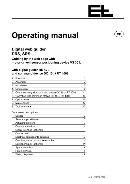
<strong>Operating</strong> <strong>manual</strong><br />
en<br />
Digital web guider<br />
DRS, SRS<br />
Guiding by the web edge with<br />
motor-driven sensor positioning device VS 351.<br />
with digital guider RK 40..<br />
and command device DO 10.. / RT 4006<br />
1. Function 3<br />
2. Assembly 7<br />
3. Installation 7<br />
4. Setup editor 9<br />
5. Commissioning with command station DO 10.. / RT 4006 11<br />
6. Operation with command station DO 10.. / RT 4006 13<br />
7. Optimization 15<br />
8. Maintenance 17<br />
9. Technical data 17<br />
Component descriptions:<br />
Sensor<br />
Sensor support beam<br />
Actuating element<br />
Command devices<br />
Digital interface (optional)<br />
Control card<br />
Electrical components (optional)<br />
CAN bus, serial bus and setup editor<br />
Service <strong>manual</strong> (optional)<br />
Spare parts lists<br />
Parameter lists<br />
Wiring diagrams<br />
B<br />
C<br />
D<br />
H<br />
I<br />
J<br />
U<br />
V<br />
W<br />
X<br />
Y<br />
Z<br />
ANL--250936-EN-01
<strong>Operating</strong> instruction notes<br />
Explanation of symbols<br />
jobs to be performed<br />
important information and instructions<br />
sections of the <strong>manual</strong> due particular attention to assure the<br />
safe operation of the web guider.<br />
<strong>Operating</strong> <strong>manual</strong> structure<br />
The E+L web guider <strong>manual</strong> consists of a general system description<br />
(A), individual component descriptions (B, C, ... W), spare parts lists<br />
(X), parameter lists (Y) and diagrams (Z).<br />
Proceed according to the operating <strong>manual</strong> instructions. All important<br />
operating procedures are explained in the <strong>manual</strong>. Where necessary,<br />
reference is made to the individual component descriptions.<br />
The block diagram includes a schematic of your system. The block<br />
diagram also includes the address settings in the case of web guiders<br />
designed by E+L.<br />
See the parameter lists for explanations of the individual setup parameters.<br />
See "Setup editor" section 4 for procedure on checking/<br />
changing parameters.<br />
Type overview<br />
The operating <strong>manual</strong> applies for web guiders with the following actuating<br />
elements:<br />
- pivoting frame DR<br />
- steering roller SR<br />
A page 2
1. Function<br />
Function<br />
1.1 Purpose The web guider positions the moving web according to the web edge.<br />
It corrects deviations from the set position and thus prevents the web<br />
wandering off to the side. Oscillating the web within the actuating element<br />
operating range and a sensor position display are possible.<br />
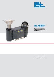
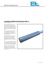
1.2 Design<br />
Actuating element<br />
Actuator AG ..<br />
Sensor<br />
Example: Web guider DRS with pivoting<br />
frame, sensor and support beam<br />
Support beam<br />
The web guider consists of the following components:<br />
- a sensor for recording the actual position<br />
- an actuating element (pivoting frame, turn rod, steering roller, reel<br />
station) with actuator and return-to-center switch<br />
- a motor-driven support beam VS 351.<br />
- a digital controller DC .. or SE .. .<br />
optional<br />
- command station DO ..<br />
- remote display DO ..<br />
- digital interface DI .. (e.g. CAN PLC, CAN ARCNET,<br />
CAN INTERBUS)<br />
1.3 <strong>Operating</strong> principle<br />
To insert the web move the actuating element to center position and<br />
drive the sensor into its outer position. Once the web is inserted,<br />
drive the sensor to the web edge. The sensor continues to follow<br />
theweb. If the web guider is in automatic mode and the guider stop<br />
contact enabled, the support beam will be blocked and the web guided.<br />
The sensor zero point corresponds to the web edge set position.<br />
The sensor scans the web edge. If the web edge deviates from its<br />
set position, the sensor passes on the magnitude and direction of the<br />
deviation to the digital controller for evaluation. The actuator corrects<br />
the web edge back to its set position via the actuating element, see<br />
control diagram.<br />
KAP--224075-EN-01 A page 3
Function<br />
1.3.1 Oscillating mode<br />
The web is offset to the left/right of its set position via the oscillating<br />
function. Use remote display DO 002. or the setup parameters to set<br />
the oscillating time and stroke. The oscillating time is specified onsite<br />
(reel station controls) for path-dependent oscillation. The web is<br />
still guided during operation.<br />
1.3.2 Position display<br />
The carriage position can be displayed in conjunction with command<br />
station DO 01.. or remote display DO 002.. The display is in mms.<br />
and may be calibrated to a specific value by the customer.<br />
A page 4
Function<br />
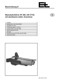
1.3.3 Control diagram<br />
mode (actuating element<br />
operating mode):<br />
a right end position limiting<br />
b center position<br />
c left end position limiting<br />
d stop<br />
e <strong>manual</strong> adjust. to right<br />
f <strong>manual</strong> adjust. to left<br />
g Automatic<br />
i<br />
k<br />
h<br />
mode (support beam operating<br />
mode):<br />
h search edge<br />
i park sensor<br />
k stop (actuating element in auto)<br />
Control diagram legend<br />
1 <strong>Operating</strong> mode (see mode)<br />
2 Actuator positioning device (e.g. pivoting frame)<br />
3 Variable max. actuating speed in <strong>manual</strong><br />
4 Speed controller<br />
5 Variable current limiting<br />
6 Power unit with current controller for actuating element<br />
7 Gearing with screw<br />
8 Righ t end position<br />
9 Center position<br />
10 Left end position<br />
11 Right offset<br />
12 Left offset<br />
13 Stored actual position (actuating element)<br />
14 Actual speed value recording<br />
15 Counter<br />
16 Incremental encoder<br />
17 Web position controller<br />
18 Variable max. actuating speed in automatic<br />
19 Stop mode<br />
20 Edge sensor<br />
21 Support beam position controller<br />
22 Support beam speed controller<br />
23 Power unit with current controller for support beam<br />
24 Sensor zero point detector<br />
25 Memory for edge position detected<br />
26 Web offset<br />
27 Park position<br />
28 Support beam position controller<br />
29 Actual speed value recording<br />
30 Counter<br />
31 Oscillation generator<br />
32 Oscillation frequency<br />
33 Oscillation amplitude<br />
34 Oscillation mode<br />
A page 5
Function<br />
A page 6
Assembly / Installation<br />
2. Assembly<br />
Please observe the locally applicable and professional safety<br />
and accident prevention regulations!<br />
2.1 Actuating element<br />
Mount actuating element according to attached description. See<br />
also dimensioned or set-up drawing.<br />
2.2 Sensors<br />
The sensors are pre-mounted on the actuating element (sensor support<br />
beam). In exceptional cases, see sensor and actuating element<br />
descriptions, application instructions section.<br />
2.3 Support beam (optional)<br />
The support beam is pre-mounted on the actuating element. In exceptional<br />
cases, see support beam description. The support beam<br />
must be mounted so that the sensors are located immediately after<br />
the actuating element, see also actuating element description, application<br />
instructions section.<br />
2.4 Digital controller<br />
The digital controller is either mounted on the actuating element or<br />
designed for mounting in a control cabinet on-site.<br />
The connection between control board and D.C. positioning drive<br />
can run in one line up to a length of 3 m. However, if the distance<br />
is between 3 m and 10 m then the motor lead and the lead of the<br />
incremental encoder MUST run seprately.<br />
2.5 Command stations<br />
(optional)<br />
The command stations should be mounted in such a way that the<br />
operator actually sees the equipment he is controlling (e.g. the<br />
support beam).<br />
3. Installation<br />
Please observe the locally applicable and professional safety<br />
and accident prevention regultions !<br />
Run electrical leads according to the attached wiring diagram.<br />
3.1 Sensor<br />
No installation work is requried for compact systems. See the sensor<br />
description for exceptions.<br />
3.2 Support beam (optional)<br />
No installation work is required for compact systems. See the description<br />
"Suppor beams" for exceptions.<br />
KAP--250504-EN-01 A page 7
Assembly / Installation<br />
A page 8
Setup editor<br />
4. Setup editor<br />
Parameters can be displayed and some even changed in setup<br />
mode. You can access setup and expanded setup mode via command<br />
station DO .... or operator panel RT .... .<br />
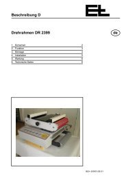
Basic operation in setup mode:<br />
Parametervalue<br />
Parameter<br />
Start setup mode: press the setup and additionally<br />
the increase value key (press the se tup key<br />
first). The green LED on the key will flash.<br />
Enter device number: press and hold down the<br />
setup key and select parameter 0 via the increase<br />
value key. Let go the setup key again and enter<br />
the device number via the increase or decrease<br />
value keys (device number is specified in block<br />
diagram)<br />
Enter group number: press and hold down the<br />
setup key and select parameter 1 via the increase<br />
value key. Let go the setup key again and enter<br />
the group number via the increase or decrease<br />
value keys (group number is specified in block<br />
diagram)<br />
Select and change parameter: press and hold<br />
down the setup key and select the parameter you<br />
require via the increase value key. Let go the setup<br />
key again and enter the parameter value you<br />
wish via the increase or decrease value keys.<br />
Start setup mode<br />
Enter device number<br />
Enter group number<br />
Select parameter<br />
Change parameter value<br />
+<br />
+<br />
or<br />
+<br />
or<br />
+<br />
or<br />
Improper parameter changes can impair<br />
the function of the entire system !<br />
parameter<br />
value can be<br />
changed<br />
yes<br />
Select expanded setup mode: select device<br />
number X.5, then press and hold down the<br />
setup key and select parameter 3 via the increase<br />
value key. Let go the setup key again and enter<br />
parameter value 42 via the increase or decrease<br />
value keys .<br />
no<br />
Expanded setup mode<br />
+<br />
or<br />
Select<br />
further parameters<br />
yes<br />
Quit setup mode: select device number X.5<br />
then press and hold down the setup key and<br />
select parameter 3 via the increase value key. Let<br />
go the setup key again and enter parameter value<br />
1 via the increase or decrease value keys. Press<br />
and hold down the setup key and press the increase<br />
value key once..Let go the setup key again.<br />
no<br />
Quit setup mode<br />
+<br />
or<br />
+<br />
X is used as a stand-in for digits<br />
KAP--250505-EN-01 A page 9
Setup editor<br />
The full device address must be entered in the setup editor before<br />
the parameters of a specific device (e.g. sensor) can be changed.<br />
The device address is made up of the device and group number.<br />
All device addresses are specified in the block diagram.<br />
Parameters are selected by pressing and holding down the setup key<br />
and then pressing the increase or decrease value key until the parameter<br />
you want appears on the display.<br />
Once you let go the setup key the parameter value will appear on the<br />
display. Use the increase or decrease value keys to change the parameter<br />
value.<br />
Values are adopted or a reaction triggered by changing parameters,<br />
i.e. by selecting the next parameter.<br />
Parameters that cannot be edited must be selected and changed in<br />
expanded setup mode.<br />
A page 10
Commissioning with command station DO 10.. / RT 4006<br />
5. Commissioning<br />
with command<br />
station DO 10.. /<br />
RT 4006<br />
No-one must be present in the danger area around the web<br />
guider during commissioning or operation. Please observe<br />
the locally applicable and professional safety regulations.<br />
Check that the connecting leads are correctly wired.<br />
Connect all web guider devices to the operating voltage.<br />
Check the CAN bus connections. The CAN bus connection LEDs<br />
on the web guider and command stations will light up green, i.e.<br />
operational. If one of the LEDs lights up red, the corresponding<br />
CAN connection has a malfunction. Check the device and CAN<br />
cabling.<br />
Position and check sensor, set if necessary (e.g. adjustment etc.)<br />
see sensor description.<br />
This terminates the commissioning for standard applications.<br />
The settings for the following functions are listed in the descripton<br />
of the control board RK 4004:<br />
Step size for web displacement by touch control<br />
Oscillation<br />
Proportional range (amplification of control loop)<br />
Positioning speed in automatic mode<br />
Positioning speed in <strong>manual</strong> mode<br />
Reduction of positioning speed in the event of a web defect<br />
Sensor emergency operation<br />
Adaptive amplification<br />
Early warning for limit of travel<br />
Programmable digital inputs<br />
Acceleration ramp <strong>manual</strong> mode<br />
Dynamic motor current elevation<br />
KAP--250506-EN-01 A page 11
Commissioning with command station DO 10.. / RT 4006<br />
A page 12
Operation with command station DO 10.. / RT 4006<br />
6. Operation with<br />
command station<br />
DO 10.. /<br />
RT 4006<br />
Only insert web when web guider and processing machine<br />
are switched off. Risk of injury!<br />
When two or more digital guiders are networked, prior to operation<br />
each individual control loop for which the following operating<br />
sequence is to apply must be selected by multifunction command-<br />
DO 0022.<br />
Enable web guider operating voltage<br />
<strong>Operating</strong> voltage display goes on.<br />
Select center mode (web guider switched off)<br />
Before inserting a new web always set the actuating element to<br />
"center" mode first.<br />
Set web offset to "0"<br />
Set web offset on command station DO 10.. to "0" (press the web<br />
offset/<strong>manual</strong> adjustment keys at the same time).<br />
Turn the web offset on command station RE 17.. (if featured) until<br />
the digital display indicates 0.0.<br />
Store set position as follows (if necessary):<br />
- Set the web to desired position.<br />
- Press "Setup" key together with the "Automatic" key. The support<br />
positions the sensor to the web edge. This position is then stored<br />
as set position.<br />
This set position remains stored until a new set position is stored.<br />
Set operating mode<br />
- Center mode: the actuating element is moved to the stored center<br />
position.<br />
- Manual mode: the actuating element can be moved to the desired<br />
location via the "web offset/<strong>manual</strong> adjustment" keys.<br />
- Automatic mode: if the guider stop contact is not connected, the<br />
web guider will go into automatic immediately.<br />
In automatic mode, the web can be offset via command station<br />
RE 17.. or the "web offset/<strong>manual</strong> adjustment" keys.<br />
KAP--250935-EN-01 A page 13
Operation with command station DO 10.. / RT 4006<br />
Start processing machine<br />
If the guider stop contact is connected the web guider will not go<br />
into automatic until enabled by the guider stop contact.<br />
Set web offset<br />
Use the web offset/<strong>manual</strong> adjustment keys to offset the web<br />
within the sensor measuring range. If a command station RE 17..<br />
is available, it alone can be used to offset the web, the "web offset/<strong>manual</strong><br />
adjustment" keys on DO 10../RT 4006 have no function.<br />
A page 14
Optimisation<br />
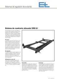
7. Optimization Amplification is correctly set if, after brief overshooting the error is<br />
7.1 Optimization premises<br />
Amplification too high<br />
Amplification right<br />
Amplification too low<br />
corrected. If the position controller is set with too great a degree<br />
of sensitivity, the guider will overshoot as well. In the case of too<br />
little amplification the control loop will be too slow. Optimum amplification<br />
may be determined with a characteristic curve tracer. In<br />
practice, amplification may also be determined by trial and error:<br />
While the web is controlled in the automatic mode it is necessary<br />
to shortly cover up the sensor measuring range (with a piece<br />
of cardboard for ex.) . A change of the web position will change<br />
the web path. The level-out behavior of the web guider provides<br />
further data on the amplification.<br />
The smaller the set proportional range at a constant maximum positioning<br />
velocity (Parameter ".1.6. velocity auto") is, the greater the<br />
amplification of the web guider will be.<br />
A negative proportional range causes negative amplification, the<br />
effective direction is thus inverted in automatic mode.<br />
established correction<br />
positioning velocity depending<br />
on proportional<br />
range<br />
Velocity correction<br />
15 mm/s<br />
8 mm/s<br />
Proportional range<br />
.1.3. prop range ±<br />
2,0 3,5<br />
Regelabweichung<br />
Positioning velocity<br />
.1.6. velocity auto<br />
20 mm/s<br />
Set position<br />
(sensor measuring range<br />
center )<br />
Control deviation of<br />
1.5 mm<br />
By reducing the proportional range the characteristic curve (see fig.)<br />
will become steeper. The steeper the characteristic curve the greater<br />
the positioning velocity will be in the case of a control deviation<br />
and the system thus more sensitive. The positioning velocity of the<br />
actuator may be determined on the basis of the characteristic curve<br />
regardless of the control deviation.<br />
KAP--250501-EN-01 A page 15
Optimisation<br />
In this example a proportional range of 2 mm or 3.5 mm has been<br />
assumed at a maximum motion speed of 20 mm/s.<br />
If the control deviation is 1,5 mm the following positioning velocity will<br />
result:<br />
15 mm/s for a proportional range of 2 mm<br />
8,0 mm/s for a proportional range of 3,5 mm<br />
The values may also be calculated arithmetically:<br />
Amplification (G) = parameter .1.6. / Parameter .1.3.<br />
Correction velocity (VK) = control deviation * amplification (G)<br />
Example 1: Example 2:<br />
G = 20/2 = 10 1 / s<br />
VK = 1,5 mm * 10 1 / s<br />
VK = 15 mm/s<br />
G = 20/3,5 = 5,71 1 / s<br />
VK = 1,5 mm * 5,71 1 / s<br />
VK = 8,6 mm/s<br />
7.2 Optimizing the proportional<br />
range<br />
Reduce the proportional range by small steps only. Following each<br />
change of the parameter value a web deviation should be produced<br />
<strong>manual</strong>ly in automatic mode so that oscillation may be detected immediately.<br />
Reduce the proportional range until the guider starts to oscillate. The<br />
increase the proportional range again until no more oscillation may<br />
be observed.<br />
+<br />
/<br />
+<br />
+<br />
. 1. 3.<br />
. . 3.<br />
1<br />
. . 4.<br />
Select operational mode "Automatic" .<br />
Select parameter ".1.3. prop range ±" .<br />
Modify parameter value as required.<br />
Smaller value = web guider more responsive<br />
Bigger value = web guider less responsive<br />
Each time the parameter value is changed the web should be deviated<br />
so that oscillation is detected immediately.<br />
Leave the setup mode after setting the proportional range.<br />
Select parameter "..3. start service".<br />
Enter parameterwert 1.<br />
Select parameter "..4.".<br />
By entering "1" into parameter "..3." and then changing to another<br />
parameter a reset with data storage is activated.<br />
If two or several digital controllers are networked it is necessary to<br />
select the equipment address of the relevant web guider before<br />
selecting the parameter, see chapter "Setup-Editor".<br />
A page 16
Maintenance / Technical data<br />
8. Maintenance<br />
Maintenance may only be performed when the web guider<br />
and processing machine are switched off .<br />
8.1 Sensor<br />
See sensor description.<br />
8.2 Support beam (optional)<br />
See support beam description.<br />
8.3 Actuating element<br />
See actuating element description.<br />
9. Technical data<br />
The technical data depend on the devices implemented and are specified<br />
in the relevant descriptions.<br />
Technical data subject to modification without notice.<br />
KAP--250502-EN-01 A page 17
Erhardt + Leimer GmbH<br />
Postfach 10 15 40<br />
D-86136 Augsburg<br />
Telephone (0821) 24 35-0<br />
Telefax (0821) 24 35-6 66<br />
Internet http://www.erhardt-leimer.com<br />
E-mail info@erhardt-leimer.com