l® RESOL DeltaSol® C Plus *48003310* 48003310 - SEG Solar ...
l® RESOL DeltaSol® C Plus *48003310* 48003310 - SEG Solar ...
l® RESOL DeltaSol® C Plus *48003310* 48003310 - SEG Solar ...

You also want an ePaper? Increase the reach of your titles
YUMPU automatically turns print PDFs into web optimized ePapers that Google loves.
<strong>RESOL</strong> DeltaSol ® C <strong>Plus</strong><br />
<strong>*<strong>48003310</strong>*</strong><br />
<strong>48003310</strong><br />
Mounting<br />
Connection<br />
Operation<br />
Troubleshooting<br />
Examples<br />
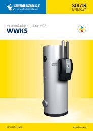
Thank you for buying this <strong>RESOL</strong> product.<br />
Please read this manual carefully, to get the best performance from this unit.<br />
DeltaSol ® C <strong>Plus</strong><br />
B<br />
Manual<br />
www.resol.de
DeltaSol ® C <strong>Plus</strong><br />
Safety advice<br />
Please pay attention to the following<br />
safety advice in order to avoid danger<br />
and damage to people and property.<br />
Instructions:<br />
Attention should be paid to<br />
- valid local regulations<br />
- the statutory provisions for prevention<br />
of industrial accidents,<br />
- the statutory provisions for environmental<br />
protection,<br />
- the Health and Safety at Work Act<br />
1974<br />
- Part P of the Building Regulations<br />
2005<br />
- BS7671 Requirements for electrical<br />
installations and relevant safety regulations<br />
of DIN, EN, DVGW, TRGI,<br />
TRF and VDE.<br />
These instructions are exclusively<br />
addressed to authorised skilled personnel.<br />
- Only qualified electricians should<br />
carry out installation and maintenance<br />
work.<br />
- Initial installation should be carried<br />
out by named qualified personnel<br />
Appropriate usage<br />
The solar controller is to be used<br />
in 1-store-, 2-store-, and east-/west<br />
collector solar thermal systems, as<br />
well as for controlling of ΔT-Kreisen<br />
unter Berücksichtigung der in dieser<br />
Anleitung angegebenen technischen<br />
Daten bestimmt.<br />
Improper use excludes all liability<br />
claims<br />
Table of contents<br />
Safety advice.......................................................................................... 2<br />
Overview of functions and technical data.................................... ......3<br />
1. Installation................................................................................ 4<br />
1.1 Mounting.......................................................................................................... 4<br />
1.2 Electrical connection..................................................................................... 4<br />
1.2.1 Data communication / bus........................................................................... 5<br />
1.2.2-9 Terminal allocation Arrangements 1-9...................................................... 6<br />
2. Operation and function......................................................... 10<br />
2.1 Buttons for adjustment...............................................................................10<br />
2.2 System-Monitoring display.........................................................................10<br />
2.2.1 Channel display.............................................................................................10<br />
2.2.2 Toolbar...........................................................................................................10<br />
2.2.3 System-Screen..............................................................................................11<br />
2.3 Flashing codes...............................................................................................11<br />
3. Commissioning....................................................................... 12<br />
4. Control parameters and and display channels.................... 13<br />
4.1 Overview of channels.................................................................................13<br />
4.1.1-7 Display channels...........................................................................................15<br />
4.1.6-22 Adjustment channels...................................................................................16<br />
5. Troubleshooting...................................................................... 21<br />
5.1 Various............................................................................................................22<br />
6. Accessory................................................................................ 24<br />
Imprint................................................................................................. 24<br />
Subject to change. Errors excepted<br />
Declaration of conformity<br />
We, <strong>RESOL</strong> Elektronische Regelungen GmbH, D-45527 Hattingen, declare<br />
under our sole responsibility that our product DeltaSol ® C complies with<br />
the following standards:<br />
EN 55 014-1<br />
EN 60 730-1<br />
According to the regulations of the above directives, the product is labelled<br />
with :<br />
89/336/EWG<br />
73/ 23/EWG<br />
Hattingen, 07.October 2007<br />
<strong>RESOL</strong> Elektronische Regelungen GmbH,<br />
ppa. Gerald Neuse<br />
© <strong>RESOL</strong> 08113 deltasol_c_plus.monen.indd<br />
| 2
DeltaSol ® C <strong>Plus</strong><br />
Functional overview<br />
!<br />
• System-Monitoring display<br />
• up to 4 temperature sensors<br />
Pt1000<br />
• 2 semiconductor relays for<br />
pump speed control<br />
• 9 basic systems to choose from<br />
• heat quantity measurement<br />
• <strong>RESOL</strong> VBus ®<br />
• function control<br />
• thermostat function<br />
<br />
<br />
• real time clock<br />
62<br />
• user-friendly operation<br />
• easy-to-mount housing and<br />
outstanding design<br />
30<br />
172<br />
Delivery scope:<br />
1 x DeltaSol ® C <strong>Plus</strong><br />
1 x accessory bag<br />
1 x spare fuse T4A<br />
2 x screws and dowels<br />
4 x strain relief and screws<br />
1 x capacitor 4,7 nF<br />
Additionally included in the full kit:<br />
2 x sensor FKP6<br />
2 x sensor FRP6<br />
111<br />
49<br />
© <strong>RESOL</strong> 08113 deltasol_c_plus.monen.indd<br />
Technical data<br />
Housing:<br />
plastic, PC-ABS and PMMA<br />
Protection type: IP 20 / DIN 40050<br />
Ambient temp.: 0 ... 40 °C<br />
Dimensions: 172 x 111 x 49 mm<br />
Mounting:<br />
wall mounting, mounting into patch<br />
panels is possible<br />
Display: system monitor for systems<br />
visualisation, 16-segment display, 7-segment<br />
display, pictograms<br />
Operation: 3 push buttons at the<br />
front of the housing<br />
Functions: Differential temperature<br />
controller with optional add-on system<br />
functions. Function control according<br />
to BAW-guidelines, operating hours<br />
counter, tube collector function, pump<br />
speed control, thermostat function and<br />
heat quantity measurement<br />
Inputs: for 4 temperature sensors<br />
Pt1000<br />
Outputs: 2 semiconductor relays<br />
Bus: <strong>RESOL</strong> VBus ®<br />
Power supply:<br />
220 ... 240 V~<br />
Total switching capacity:<br />
2 (2) A (220 ... 240) V~<br />
Switching capacity per relay:<br />
semiconductor relay:<br />
1 (1) A (220 ... 240) V~<br />
3 |
DeltaSol ® C <strong>Plus</strong><br />
1. Installation<br />
1.1 Mounting<br />
cover<br />
display<br />
push button<br />
WARNING!<br />
Always disconnect the controller<br />
from power supply before opening<br />
the housing!<br />
The unit must only be located in dry interior locations. It<br />
is not suitable for installation in hazardous locations and<br />
should not be placed close to any electromagnetic fields. The<br />
controller must additionally be supplied from a double pole<br />
switch with contact gap of at least 3 mm. Please pay attention<br />
to separate routing of sensor cables and mains cables.<br />
1. Unscrew the cross-head screw from the cover and remove<br />
it along with the cover from the housing.<br />
2. Mark the upper fastening point on the wall and drill and<br />
fasten the enclosed wall plug and screw leaving the head<br />
protruding.<br />
3. Hang the housing from the upper fastening point and<br />
mark the lower fastening point through the hole in the<br />
terminal box (centres 130 mm). Drill and insert the lower<br />
wall plug.<br />
4. Hang the housing from the upper fastening point and<br />
tighten lower fastening screw.<br />
cable conduit with<br />
strain relief<br />
130<br />
fastening<br />
base<br />
fuse<br />
fastening<br />
1.2 Electrical connection<br />
<strong>Plus</strong><br />
sensor terminals<br />
VBus<br />
9 10<br />
VBus<br />
ground terminals<br />
load terminals<br />
fuse<br />
mains terminals<br />
Electrostatic discharge can cause damage of electronic<br />
components!<br />
High-voltage components!<br />
Note:<br />
The relays are semiconductor relays for pump speed control.<br />
A minimum load of 20 W (power consumption of the<br />
load) is required for faultless function. The capacitor from<br />
th e accessory bag must be connected in parallel to the<br />
respective relay output if it feeds auxiliary relays, motor<br />
valves, etc.<br />
Attention: The minimum pump speed must be set to 100%<br />
when auxiliary relays or valves are connected.<br />
The power supply to the controller must be carried out via<br />
an external power switch (last step!) and the supply voltage<br />
must be 220 ... 240 V~ (50... 60 Hz). Flexible cables must be<br />
attached to the housing with the enclosed strain relief and<br />
the corresponding screws.<br />
The controller is equipped with 2 relays to which loads<br />
such as pumps, valves etc. can be connected:<br />
• Relay 1<br />
18 = conductor R1<br />
17 = neutral conductor N<br />
13 = ground clamp<br />
• Relay 2<br />
16 = conductor R2<br />
15 = neutral conductor N<br />
14 = ground clamp<br />
The temperature sensors (S1 to S4) have to be connected<br />
to the following terminals (either polarity):<br />
1 / 2 = sensor 1 (e. g. sensor collector 1)<br />
3 / 4 = sensor 2 (e. g. sensor store 1)<br />
5 / 6 = sensor 3 (e. g. sensor collector 2)<br />
7 / 8 = sensor 4 (e. g. sensor store TRF)<br />
The mains connection is at the terminals:<br />
19 = neutral conductor N<br />
20 = conductor L<br />
12 = ground clamp<br />
© <strong>RESOL</strong> 08113 deltasol_c_plus.monen.indd<br />
| 4
DeltaSol ® C <strong>Plus</strong><br />
1.2.1 Data communication / bus<br />
<strong>Plus</strong><br />
VBus<br />
9 10<br />
The controller is equipped with the <strong>RESOL</strong> VBus ® for<br />
data transfer with and energy supply to external modules.<br />
The connection is carried out at the two terminals 9 and<br />
10 marked “VBus ® “ (either polarity). One or more <strong>RESOL</strong><br />
VBus ® modules can be connected via this data bus:<br />
• <strong>RESOL</strong> calorimeter<br />
• <strong>RESOL</strong> large display / Smart Display<br />
• <strong>RESOL</strong> datalogger<br />
• <strong>RESOL</strong> data remote display<br />
The RS232-interface for direct connection to a PC. Measured<br />
values and parameters of the controller can be<br />
read out, adjusted, processed and visualised by means<br />
of the evaluation tool RSC (Resol Service Center Software).<br />
The software allows easier paramatrisation and<br />
RS232-connection function control of the system.<br />
The light version is free for download at www.resol.de.<br />
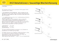
1.2.2 Terminal allocation Arr 1 Standard solar system with 1 store, 1 pump and 3<br />
sensors. Sensor S4 / TRF can optionnally be used for heat<br />
quantity measurement.<br />
ARR 1<br />
S1<br />
© <strong>RESOL</strong> 08113 deltasol_c_plus.monen.indd<br />
R1<br />
S4 / TRF<br />
S3<br />
S2<br />
Symbol Description<br />
S1 collector sensor<br />
S2 store sensor base<br />
S3 store sensor top /<br />
(optional)<br />
S4 / TRF sensor for heat quantity<br />
measurement (optional)<br />
R1<br />
solar pump<br />
5 |
DeltaSol ® C <strong>Plus</strong><br />
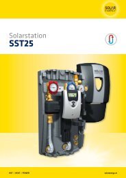
1.2.3 Terminal allocation Arr 2 <strong>Solar</strong> system and heat exchange to existant store<br />
with 2 stores, 4 sensors and 2 pumps.<br />
ARR 2<br />
S1<br />
R1<br />
S3<br />
store 1 store 2<br />
S2<br />
R2<br />
S4<br />
Symbol Description<br />
S1 collector sensor<br />
S2 store base sensor<br />
S3 store top sensor<br />
S4 store sensor 2<br />
R1<br />
solar pump<br />
R2<br />
pump for<br />
heat exchange<br />
1.2.4 Terminal allocation Arr 3 <strong>Solar</strong> system and after-heating with 1 store, 3 sensors<br />
and after-heating. Sensor S4 / TRF can optionnally be used<br />
for heat quantity measurement.<br />
ARR 3<br />
S1<br />
R1<br />
S4 / TRF<br />
S2<br />
S3<br />
R2<br />
Symbol<br />
S1<br />
S2<br />
S3<br />
S4 / TRF<br />
R1<br />
R2<br />
Description<br />
collector sensor<br />
store sensor base<br />
store sensor top<br />
Sensor for heat quantity<br />
measurement (optional)<br />
solar pump<br />
charging pump<br />
after-heating<br />
© <strong>RESOL</strong> 08113 deltasol_c_plus.monen.indd<br />
| 6
DeltaSol ® C <strong>Plus</strong><br />
1.2.5 Terminal allocation Arr 4<br />
<strong>Solar</strong> system and vertical store charging with 1 store,<br />
3 sensors, 1 solar pump and 3-port valve for vertical store<br />
charging. Sensor S4 / TRF can optionnally be used for heat<br />
quantity measurement.<br />
ARR 4<br />
S1<br />
R1<br />
S4 / TRF<br />
R2<br />
S3<br />
S2<br />
Symbol<br />
S1<br />
S2<br />
S3<br />
S4 / TRF<br />
Description<br />
collector sensor<br />
store sensor base<br />
store sensor top<br />
sensor for heat quantity<br />
measurement (optional)<br />
R1<br />
R2<br />
solar pump<br />
3-port valve<br />
1.2.6 Terminal allocation Arr 5<br />
2-store solar system with valve control with 2 stores,<br />
3 sensors, 1 solar pump and 1 3-port valve. Sensor S4 / TRF<br />
can optionnally be used for heat quantity measurement.<br />
ARR 5<br />
S1<br />
R2<br />
R1<br />
© <strong>RESOL</strong> 08113 deltasol_c_plus.monen.indd<br />
S4 / TRF<br />
store 1 store 2<br />
S2<br />
S3<br />
Symbol Description<br />
S1 collector sensor<br />
S2 store sensor 1<br />
S3 store sensor 2<br />
S4 / TRF sensor for heat quantity<br />
measurement (optional)<br />
R1<br />
R2<br />
solar pump<br />
3-port valve<br />
7 |
DeltaSol ® C <strong>Plus</strong><br />
1.2.6 Terminal allocation Arr 6 2-store solar system with pump control with 2 stores,<br />
3 sensors and 2 solar pumps.<br />
ARR 6<br />
S1<br />
S4<br />
R1<br />
R2<br />
store 1 store 2<br />
S2<br />
S3<br />
Symbol Description<br />
S1 collector sensor<br />
S2 store sensor 1<br />
S3 store sensor 2<br />
S4 sensor (optional)<br />
R1 solar pump store 1<br />
R2 solar pump store 2<br />
1.2.7 Terminal allocation Arr 7 <strong>Solar</strong> system with east-/west collectors, 1 store, 3<br />
sensors and 2 solar pumps.<br />
ARR 7<br />
S1<br />
S3<br />
R1<br />
R2<br />
S2<br />
Symbol Description<br />
S1 collector sensor 1<br />
S2<br />
store sensor<br />
S3 collector sensor 2<br />
S4 sensor (optional)<br />
R1 solar pump collector 1<br />
R2 solar pump collector 2<br />
© <strong>RESOL</strong> 08113 deltasol_c_plus.monen.indd<br />
| 8
DeltaSol ® C <strong>Plus</strong><br />
1.2.8 Terminal allocation Arr 8<br />
<strong>Solar</strong> system with after-heating with solid fuel boiler<br />
with 1 store 4 sensors, 1 solar pump and 1 pump for afterheating.<br />
ARR 8<br />
S1<br />
R1<br />
S3<br />
S4<br />
S2<br />
R2<br />
Symbol<br />
S1<br />
S2<br />
S3<br />
S4<br />
R1<br />
R2<br />
Description<br />
collector sensor<br />
store sensor base<br />
store sensor top<br />
sensor for solid fuel boiler<br />
solar pump<br />
pump for solid fuel boiler<br />
1.2.9 Terminal allocation Arr 9<br />
<strong>Solar</strong> system and heating circuit return preheating with<br />
1 store, 4 sensors, 1 solar pump and 1 3-port valve for heating<br />
circuit return preheating.<br />
ARR 9<br />
S1<br />
R1<br />
S4<br />
S3<br />
© <strong>RESOL</strong> 08113 deltasol_c_plus.monen.indd<br />
S2<br />
R2<br />
Symbol<br />
S1<br />
S2<br />
S3<br />
S4<br />
R1<br />
R2<br />
Description<br />
collector sensor<br />
store sensor base<br />
store sensor top<br />
heating circuit - return<br />
solar pump<br />
3-port valve<br />
9 |
DeltaSol ® C <strong>Plus</strong><br />
2. Operation and function<br />
2.1 Buttons for adjustment<br />
1 forwards<br />
3<br />
2<br />
SET<br />
(selection/adjustment<br />
mode)<br />
backwards<br />
Connect the controller to the mains. The controller is in<br />
an initialisation phase. After this phase, the controller is in<br />
automatic operation with factory settings.<br />
The controller is operated via the 3 push buttons below the<br />
display. The forward-button (1) is used for scrolling forward<br />
through the menu or to increase the adjustment values. The<br />
backward-button (2) is similarly used for scrolling backwards<br />
and reducing values.<br />
In order to access the adjustment mode, scroll down in the<br />
display menu and press the forward button (1) for approx.<br />
2 seconds after you have reached the last display item. If<br />
an adjustment value is shown on the display, the icon<br />
is displayed. Now, you can access the adjustment mode by<br />
using button 3.<br />
— Press buttons 1 and 2 in order to select a channel<br />
— Briefly press button 3, appears (flashing) (<br />
-mode)<br />
— adjust the requested value by pressing the buttons 1 and 2<br />
— Briefly press button 3, so that permanently appears,<br />
the adjusted value will be saved.<br />
2.2 System-Monitoring display<br />
!<br />
<br />
<br />
The system monitoring display consists of 3 ranges: The<br />
channel display, the toolbar and the system-screen<br />
(active arrangement).<br />
Monitoring-Display<br />
2.2.1 Channel display<br />
2.2.2 Toolbar<br />
channel display<br />
The channel display consists of 2 lines. The upper line is an<br />
alpha-numeric 16-segment display (text display) for displaying<br />
channel names and menu items. In the lower 7-segment<br />
display, the channel values and the adjustment parameters<br />
are displayed.<br />
Temperatures and temperature differences are indicated<br />
in or .<br />
The additional symbols in the toolbar indicate the actual<br />
system status.<br />
| 10<br />
toolbar<br />
symbol normal flashing<br />
relay 1 active<br />
relay 2 active<br />
store maximum limitation<br />
active / maximum store<br />
temperature exceeded<br />
antifreeze function active<br />
+ sensor fault<br />
+ manual mode<br />
collector cooling function active<br />
recooling function active<br />
collector minimum limitation<br />
active<br />
antifreeze function active<br />
collector emergency shutdown<br />
active or store emergency<br />
shutdown active<br />
change of adjustment channel<br />
SET-mode<br />
© <strong>RESOL</strong> 08113 deltasol_c_plus.monen.indd
DeltaSol ® C <strong>Plus</strong><br />
2.2.3 System-Screen<br />
System screen<br />
The system screen (active arrangement) shows the scheme<br />
which has been selected. The screen consists of several<br />
system component symbols, which are - depending on the<br />
current status of the system - either flashing, permanently<br />
shown or „hidden“.<br />
sensor<br />
sensor store bottom<br />
heating circuit<br />
collector<br />
valve<br />
pumps<br />
store heat exchanger<br />
store<br />
store 2 or afterheating (with<br />
additional symbol)<br />
valve<br />
sensor<br />
additional symbol<br />
operation of the<br />
burner<br />
collectors<br />
with collector sensor<br />
store 1 and 2<br />
with heat exchanger<br />
temperature sensor<br />
heating circuit<br />
pump<br />
3-port valve<br />
indicates the flow direction bzw. momentane<br />
Schaltstellung angezeigt.<br />
after-heating<br />
with burner symbol<br />
© <strong>RESOL</strong> 08113 deltasol_c_plus.monen.indd<br />
2.3 Flashing codes<br />
• Pump symbols are flashing during the initialisation phase<br />
• Sensor symbols are flashing when the corresponding sensor<br />
display channel is selected.<br />
• Sensor symbols are flashing in the case of a sensor fault<br />
• Burner symbol is flashing when the after-heating is active.<br />
11 |
DeltaSol ® C <strong>Plus</strong><br />
3. Commissioning<br />
When the controller is commissionend for the first time, the arrangement has to be<br />
selected first<br />
1. Switch on power supply. After initialisation, the controller<br />
is in the automatic mode with typical settings. The preprogrammed<br />
system scheme is Arr 1.<br />
2. Adjust the actual clock time in the TIME channel. Pressing<br />
the -key for 2 seconds will display the hours, pressing<br />
1 forwards<br />
the button again will display the minutes (flashing). Time<br />
can be adjusted using buttons 1 and 2. Save the changes<br />
SET<br />
by pressing the -key.<br />
3 (selection / 3. - Select the ARR channel<br />
adjustment mode)<br />
- Change into the -mode (see 2.1)<br />
2 backwards<br />
- Selct the system arrangement via the ARR number<br />
- Save adjustments by pressing the -key<br />
Now the controller is ready for operation with typical settings<br />
to suit that system and normally the factory settings<br />
will give close to optimum operation.<br />
ARR 1 ARR 2<br />
ARR 3 ARR 4<br />
ARR 5 ARR 6<br />
Overview of arrangements:<br />
ARR 1 : standard solar thermal system<br />
ARR 2 : solar thermal system with heat exchange<br />
ARR 3 : solar thermal system with after-heating<br />
ARR 4 : solar thermal system with vertical store charging<br />
ARR 5 : 2-store solar thermal system with valve control<br />
ARR 6 : 2-store solar thermal system with pump control<br />
ARR 7 : solar thermal system with 2 collectors and 1 store<br />
ARR 8 : solar thermal system with after-heating with solid<br />
fuel boiler<br />
ARR 9 : solar thermal system heating circuit return preheating<br />
ARR 7 ARR 8<br />
ARR 9<br />
| 12<br />
© <strong>RESOL</strong> 08113 deltasol_c_plus.monen.indd
DeltaSol ® C <strong>Plus</strong><br />
4. Regelparameter und Anzeigekanäle<br />
4.1 Kanal-Übersicht<br />
Legende:<br />
x<br />
Corresponding channel is available.<br />
x*<br />
Corresponding channel is available when the corresponding<br />
option is enabled<br />
Note:<br />
Only if temperature sensors are connected, will S3 and S4<br />
be displayed.<br />
<br />
Only if the option heat quantity measurement is activated<br />
(OHQM), will the corresponding channel be available.<br />
<br />
Only if the option heat quantity measurement is deactivated<br />
(OHQM), will the corresponding channel be available.<br />
MEDT<br />
Only if an antifreeze (MEDT) other than water or Tyfocor<br />
LS / G-LS (MEDT 0 or 3) is used, will the channel<br />
antifreeze concentration (MED%) be displayed. The adjustment<br />
of the antifreeze concentration has only to be carried<br />
out when an antifreeze is used in the solar circuit.<br />
channel<br />
ARR<br />
1 2 3 4 5 6 7 8 9<br />
descritption<br />
COL x x x x x x x x temperature collector 1 15<br />
COL 1 x temperature collector 1 15<br />
TST x x temperature store 1 15<br />
TSTU x x x x temperature store 1 base 15<br />
TST1 x x x temperature store 1 base 15<br />
TSTO x x x x x temperature store 1 top 15<br />
TST2 x x x temperature store 2 base 15<br />
TFSK x temperature solid fuel boiler 15<br />
TREC x temperature heating circuit 15<br />
COL2 x temperature collector 2 15<br />
S3 x temperature sensor 3 15<br />
TRF temperature return temperature sensor 15<br />
S4 x x temperature sensor 4 15<br />
n % x x x x speed relay 1 15<br />
n1 % x x x x x speed relay 1 15<br />
n2 % x x x x speed relay 2 15<br />
hP x x x x operating hours relay 1 16<br />
h P1 x x x x x operating hours relay 1 16<br />
h P2 x x x x x operating hours relay 2 16<br />
kWh heat quantity kWh 16<br />
page<br />
© <strong>RESOL</strong> 08113 deltasol_c_plus.monen.indd<br />
MWh heat quantity MWh 16<br />
time x time 15<br />
ARR 1-9 arrangement 12<br />
DT O x x x x x x switch-on temperature difference 17<br />
DT1O x x x switch-on temperature difference 1 17<br />
DT F x x x x x x switch-off temperature difference 1 17<br />
DT S x x x x x x set temperature difference 17<br />
RIS x x x x x x rise 17<br />
DT1F x x x switch-off temperature difference 17<br />
RIS1 x x x rise 1 17<br />
DT1S x x x set temperature difference 1 17<br />
S MX x x x x x x maximum temperature store 1 17<br />
S1 MX x x x maximum temperature store 1 17<br />
DT2O x x x switch-off temperature difference 2 17<br />
DT2F x x x switch-off temperature difference 2 17<br />
DT2S x x x set temperature difference 2 17<br />
RIS2 x x x rise 2 17<br />
S2MX x x x maximum temperature store 2 17<br />
EM x x x x x x x x emergency temperature collector 1 18<br />
EM1 x emergency temperature collector 1 18<br />
13 |
DeltaSol ® C <strong>Plus</strong><br />
channel<br />
ARR<br />
1 2 3 4 5 6 7 8 9<br />
description<br />
OCX x x x x x x x x option collector cooling collector 1 18<br />
OCX1 x option collector cooling collector 1 18<br />
CMX x* x* x* x* x* x* x* x* maximum temperature collector 1 18<br />
CMX1 x* maximum temperature collector 1 18<br />
OCN x x x x x x x x option minimum limitation collector 1 18<br />
OCN1 x option minimum limitation collector 1 18<br />
CMN x* x* x* x* x* x* x* x* minimum temperature collector 1 18<br />
CMN1 x* minimum temperature collector 1 18<br />
OKF x x x x x x x x option frost protection collector 1 18<br />
OKF1 x option frost protection collector 1 18<br />
CFR x* x* x* x* x* x* x* x* frost protection temperature collector 1 18<br />
CFR1 x* frost protection temperature collector 1 18<br />
EM2 x emergency temperature collector 2 18<br />
OCX2 x option collector cooling collector 2 18<br />
CMX2 x* maximum temperature collector 2 18<br />
OCN2 x option minimum limitation collector 2 18<br />
CMN2 x* minimum temperature collector 2 18<br />
OCF2 x option frost protection collector 2 18<br />
CFR2 x* frost protection temperature collector 2 18<br />
PRIO x x x priority 19<br />
tST x x x loading break time 19<br />
tCIRC x x x oscillating loading time 19<br />
OREC x x x x x x x x x option recooling 19<br />
O TC x x x x x x x x x option tube collector 19<br />
DT3O x x switch-on temperature difference 3 17<br />
DT3F x x switch-off temperature difference 3 17<br />
DT3S x x set temperature DT3 17<br />
RIS3 x x rise DT3 17<br />
MX3O x x switch-on threshold for maximum temp. 17<br />
MX3F x x switch-off threshold for maximum temp. 17<br />
MN3O x x switch-on threshold for minimum temp. 17<br />
MN3F x x switch-off threshold for minimum temp.. 17<br />
AH O x switch-on temperature thermostat 1 20<br />
AH F x switch-off temperature thermostat 1 20<br />
t1 O x switch-on time 1 thermostat 20<br />
t1 F x switch-off time 1 thermostat 20<br />
t2 O x switch-on time 2 thermostat 20<br />
t2 F x switch-off time 2 thermostat 20<br />
t3 O x switch-on time 3 thermostat 20<br />
t3 F x switch-off time 3 thermostat 20<br />
n2MN x x x x minimum speed relay 2 20<br />
HND1 x x x x x x x x x manual operation relay 1 20<br />
HND2 x x x x x x x x x manual operation relay 2 20<br />
LANG x x x x x x x x x Language 20<br />
PROG XX.XX program number<br />
VERS X.XX version number<br />
page<br />
© <strong>RESOL</strong> 08113 deltasol_c_plus.monen.indd<br />
| 14
DeltaSol ® C <strong>Plus</strong><br />
4.1.1 Collector temperatures<br />
COL, COL1, COL2:<br />
Collector temperatures<br />
display range: -40 ... +250 °C<br />
Displays the actual collector temperature.<br />
• COL : collector temperature (1-collector system)<br />
• COL1 : collector temperature 1<br />
• COL2 : collector temperature 2<br />
4.1.2 Store temperatures<br />
TST, TSTL, TSTU,<br />
TST1, TST2:<br />
Store temperatures<br />
Display range: -40 ... +250 °C<br />
Displays the actual store temperature.<br />
• TST : store temperature (1-store system)<br />
• TSTL : store temperature base<br />
• TSTU : store temperaturer top<br />
• TST1 : temperature store 1<br />
• TST2 : temperature store 2<br />
4.1.3 Sensors 3 and 4<br />
S3, S4:<br />
Sensor temperatures<br />
Display range: -40 ... +250 °C<br />
Display of the current temperature at the corresponding<br />
additional sensor (without control function).<br />
• S3 : temperature sensor 3<br />
• S4 : temperature sensor 4<br />
Note: Only if temperature sensors are connected, will<br />
S3 and S4 be displayed<br />
4.1.4 Other temperatures<br />
TSFB, TREC, TRF:<br />
Other measured temperatures<br />
Display range: -40 ... +250 °C<br />
Display of the current temperature at the corresponding<br />
sensor.<br />
• TSFB : temperature solid fuel boiler<br />
• TREC : temperature heating return<br />
• TRF : temperature return<br />
4.1.5 Pump speed<br />
n %, n1 %, n2 %:<br />
Actual pump speed<br />
Display range: 30 ... 100 %<br />
Display of the actual speed of the corresponding pump.<br />
• n % : actual pump speed (1-pump system)<br />
• n1 % : actual speed pump 1<br />
• n2 % : actual speed pump 2<br />
© <strong>RESOL</strong> 08113 deltasol_c_plus.monen.indd<br />
4.1.6 Time<br />
In this channel the current time is indicated.<br />
Press button for 2 seconds, the hours will then be<br />
displayed. Press the button again, the minutes will then be<br />
displayed (flashing). The time can be set using buttons 1 and<br />
2 and saved by pressing the button.<br />
15 |
DeltaSol ® C <strong>Plus</strong><br />
4.1.7 Operating hours counter<br />
h P / h P1 / h P2:<br />
Operating hours counter<br />
Display channel<br />
The operating hours counter accumulates the solar operating<br />
hours of the respective relay (h P / h P1 / h P2). Full<br />
hours are displayed.<br />
The accumulated operating hours can be set back to zero.<br />
As soon as one operating hours channel is selected, the symbol<br />
is displayed. Press the SET (3) button for approx. 2<br />
seconds in order to access the RESET-mode of the counter.<br />
The display symbol will flash and the operating hours<br />
will be set to 0. Confirm the reset with the button in<br />
order to finish the reset.<br />
In order to interrupt the RESET-process, do not press a<br />
button for about 5 seconds. The display returns to the<br />
display mode.<br />
4.1.8 Heat quantity measurement<br />
OHQM: Heat quantity<br />
measurement<br />
Adjustment range: OFF...ON-<br />
Factory setting: OFF<br />
FMAX: Flow rate in l/min<br />
Adjustment range 0...20,<br />
in 0.1 steps<br />
Factory setting: 6,0<br />
MEDT: Antifreeze type<br />
Adjustment range: 0...3<br />
Factory setting: 1<br />
MED%: Antifreeze concentration<br />
in (Vol-) %<br />
When MEDT 0 or 3 is used,<br />
the parameter MED% is<br />
‚hidden‘.<br />
Adjustment range: 20... 70<br />
Factory setting: 45<br />
Heat quantity measurement is possible in systems (ARR) 1,<br />
3, 4 and 5 if a flowmeter is used. For this purpose, the heat<br />
quantity measurement option OHQM has to be enabled.<br />
The flow rate should be read from the flowmeter (l/min)<br />
and has to be adjusted in the channel FMAX. Antifreeze<br />
type and concentration of the heat transfer medium have<br />
to be adjusted in the channels MEDT and MED%.<br />
Frostschutzart:<br />
Antifreeze type:<br />
0 : water<br />
1 : propylene glycol<br />
2 : ethylene glycol<br />
3 : Tyfocor ® LS / G-LS<br />
kWh/MWh:Heat quantity<br />
kWh / MWh<br />
Display channel<br />
| 16<br />
The flow rate as well as the reference sensors S1 (flow) and<br />
S4 (return) are used for calculating the heat quantity supplied.<br />
It is shown in kWh in the channel kWh uand in MWh<br />
in the channel MWh . The overall heat quantity results from<br />
the sum of both values.<br />
The accumulated operating hours can be set back to zero.<br />
As soon as one of the display channels of the heat quantity<br />
is selected, the symbol is displayed. Press the SET (3)<br />
button for approx. 2 seconds in order to access the RESETmode<br />
of the counter. The display symbol will flash and<br />
the heat quantity value will be set to 0. Confirm the reset<br />
with the button in order to finish the reset.<br />
In order to interrupt the RESET process, no button should<br />
be pressed for about 5 seconds. The display returns to the<br />
display mode.<br />
© <strong>RESOL</strong> 08113 deltasol_c_plus.monen.indd
DeltaSol ® C <strong>Plus</strong><br />
4.1.9 ∆T-control<br />
DT O / DT1O / DT2O /<br />
DT3O:<br />
Switch-on temperature difference<br />
Adjustment range: 1,0 ... 20,0 K<br />
Factory setting: 6.0<br />
DT F / DT1F / DT2F / DT3F:<br />
Switch-off temperature<br />
difference<br />
Adjustment range: 0,5 ... 19,5 K<br />
Factory setting: 4.0 K<br />
DT S / DT1S / DT2S /<br />
DT3S:<br />
Set temperature difference<br />
Adjustment range: 1,5 ... 30,0 K<br />
Factory setting: 10.0<br />
RIS / RIS1 / RIS2 / RIS3:<br />
Rise<br />
Adjustment range: 1 ... 20 K<br />
Factory setting: 2 K<br />
This function is a standard differential control. If the switchon<br />
differential is reached (DT O / DT1O / DT2O) the<br />
pump is operated. The pump runs at 100% speed for 10<br />
seconds. After this period, the pump runs at minimum<br />
pump speed (nMN = 30 %) gefahren. f the temperature<br />
difference reaches the adjusted set value (DT S / DT1S<br />
/ DT2S / DT3S), spump speed will increase by one step<br />
(10 %). If the difference increases by 2 K (RIS / RIS1 /<br />
RIS2 / RIS3) pump speed will increase by 10 % respectively<br />
until the maximum pump speed of 100 % is reached.<br />
The response of the controller can be adapted via the<br />
parameter „Rise“ If the temperature difference falls below<br />
the adjusted switch-off temperature difference<br />
(DT F / DT1F / DT2F) the controller switches off.<br />
DT O and DT S are blocked against each other. DT S must<br />
be at least 0,5 K higher than DT O.<br />
Please note: Switch-on temperature difference must<br />
be at least 1 K higher than the switch-off tempe rature<br />
difference.<br />
4.1.10 Maximum store temperature If the adjusted maximum temperature is exceeded, the store<br />
will no longer be loaded in order to avoid damage caused by<br />
overheating. If the maximum store temperature is exceeded,<br />
(flashing) is shown on the display.<br />
S MX / S1MX / S2MX:<br />
Maximum store temperature<br />
Adjustment range: 2 ... 95 °C<br />
Factory setting: 60 °C<br />
Note: The controller is equipped with a store emergency<br />
shutdown function, which prevents the store from being<br />
loaded when the store temperature exceeds 95 °C.<br />
4.1.11 ∆T-control (solid fuel boiler and heat exchange)<br />
© <strong>RESOL</strong> 08113 deltasol_c_plus.monen.indd<br />
Maximum temperature limitation<br />
MX3O / MX3F:<br />
Maximum temperature<br />
limitation<br />
Adjustment range: 0,0 ... 95,0 °C<br />
Factory setting:<br />
MX3E 60,0 °C<br />
MX3A 58,0 °C<br />
Minimum temperature limitation<br />
MN3O / MN3F:<br />
Minimum temperature<br />
limitation<br />
Adjustment range: 0,0 ... 90,0 °C<br />
Factory setting:<br />
ARR = 2<br />
MN3O 5,0 °C<br />
MN3F 10,0 °C<br />
ARR = 8<br />
MN3O 60,0 °C<br />
MN3F 65,0 °C<br />
The controller is equipped with an independent temperature<br />
differential control function for which minimum and<br />
maximum temperature limations as well as the corresponding<br />
switch-on and -off temperatures can be separately<br />
adjusted. For ARR = 2 and 8 only (solid fuel boiler and heat<br />
exchange control).<br />
If the adjustet value MX3O is exceeded, relay 2<br />
will be switched off. If the temperature falls below<br />
the value MX3F, the relay will be energised.<br />
Reference sensors:<br />
S3 for ARR 8 (TSTU)<br />
S4 for ARR 2 (TST2).<br />
If the temperature falls below MN3O, relay<br />
2 will be switched off. If the value MN3F is<br />
exceeded, the relay will be energised.<br />
Reference sensors:<br />
S4 for ARR 8 (TSFB)<br />
S3 for ARR 2 (TSTU).<br />
The switch on- and switch off temperature differences<br />
DT3O and DT3F also apply to the maximum- and minimum<br />
temperature limitation.<br />
17 |
DeltaSol ® C <strong>Plus</strong><br />
4.1.12 Collector-limit temperature<br />
Collector emergency shutdown<br />
EM / EM1 / EM2:<br />
Collector emergeny shutdown<br />
temperature<br />
Adjustment range: 110 ... 200 °C<br />
Factory setting: 140 °C<br />
If the adjusted collector emergency shutdown temperature<br />
(NOT / NOT1 / NOT2) is exceeded, the controller will<br />
switch off the solar pump (R1 / R2) in order to protect the<br />
system against overheating (collector emergency shutdown).<br />
The factoring setting is 140 °C but it can be changed within<br />
the adjustment range of 110 ... 200 °C. If the temperature is<br />
exceeded, (flashing) is shown on the display.<br />
4.1.13 System cooling When the adjusted maximum store temperature is reached,<br />
the system stagnates. If the collector temperature increases<br />
OCX / OCX1 / OCX2:<br />
to the adjusted maximum collector temperature (CMX<br />
System cooling option<br />
/ CMX1 / CMX2) the solar pump is activated until the<br />
Adjustment range: OFF ... ON<br />
collector temperature falls below the maximum collector<br />
Factory setting: OFF<br />
temperature. The store temperature may increase (subordinate<br />
active maximum store temperature), but only up<br />
CMX / CMX1 / CMX2:<br />
to 95 °C (emergency shutdown of the store). If the store<br />
Maximum collector<br />
temperature is higher than the maximum store temperature<br />
temperature<br />
(S MX / S1MX / S2MX) and if the collector temperature<br />
Adjustment range: 100... 190 °C<br />
is at least 5 K below the store temperature, the solar system<br />
Factory setting: 120 °C<br />
remains activated until the store is cooled down below the<br />
adjusted maximum temperature (S MX / S1MX / S2MX)<br />
via the collector and the pipework (only if the OREC<br />
function is activated).<br />
If the system cooling function is enabled, (flashing) is<br />
shown on the display. Due to the cooling function, the system<br />
will have a longer operation time on hot summer days<br />
and guarantees thermal relief of the collector field and the<br />
heat transfer fluid.<br />
4.1.14 Collector minimum limitation option<br />
OCN / OCN1 / OCN2:<br />
Collector minimum limitation<br />
Adjustment range: OFF / ON<br />
Factory setting: OFF<br />
CMN / CMN1 / CMN2:<br />
Collector minimum<br />
temperature<br />
Adjustment range: 10 ... 90 °C<br />
Factory setting: 10 °C<br />
The minimum collector temperature is the minimum temperature<br />
which must be exceeded for the solar pump (R1<br />
/ R2) to switch on. The minimum temperature prevents the<br />
pump from being switched on too often at low collector<br />
temperatures. If the temperature falls below the minimum<br />
temperature, (flashing) is shown on the display.<br />
4.1.15 Frost protection function option<br />
OCF / OCF1 / OCF2:<br />
Frost protection function<br />
Adjustment range: OFF / ON<br />
Factory setting: OFF<br />
CFR / CFR1 / CFR2:<br />
Frost protection temperature<br />
Adjustment range: -10 ... 10 °C<br />
Factory setting: 4,0 °C<br />
| 18<br />
The antifreeze function activates the loading circuit between<br />
the collector and the store when the temperature falls below<br />
the adjusted antifreeze temperature. This will protect<br />
the fluid against freezing or coagulating. If the adjusted antifreeze<br />
temperature is exceeded by 1 °C, the loading circuit<br />
will be deactivated.<br />
Note:<br />
Since this function uses the limited heat quantity of the<br />
store, the antifreeze function should be used in regions with<br />
few days of temperatures around the freezing point.<br />
© <strong>RESOL</strong> 08113 deltasol_c_plus.monen.indd
DeltaSol ® C <strong>Plus</strong><br />
4.1.16 Store sequence control<br />
Corresponding adjustment values:<br />
Factory setting<br />
Adjustment range<br />
Priority [PRIO] (1 / ARR 5,6) (2 / ARR 4) 0-2<br />
Loading break time [tSP] 2 min. 1-30 min.<br />
Oscillating loading time [tUMW] 15 min. 1-30 min.<br />
The DeltaSol ® C <strong>Plus</strong> priority logic:<br />
Priority:<br />
The options and parameters mentioned above are used in<br />
multi-store systems only (system ARR = 4, 5, 6). If priority<br />
is set to 0, the stores with a temperature difference to the<br />
collector are loaded in numerical order (store 1 or 2;<br />
ARR= 4, 5). Basically, only one store can be loaded at a time.<br />
In ARR the stores can be loaded in parallel.<br />
Loading break time / store sequence control: /<br />
collector rise temperature:<br />
When the priority store cannot be loaded, the subordinate<br />
stores are checked. If a subordinate store can be loaded, it<br />
will be loaded for the “oscillating loading time“ (“t-circ.“).<br />
After this period of time, the loading process stops. The<br />
controller monitors the increase in collector temperature.<br />
If it increases by the “collector rise temperature (∆T-col 2<br />
K, software value) within the loading break time (t-st) the<br />
elapsed break time is set to 0. The break time starts again.<br />
the switch-on condition of the priority store is not fulfilled,<br />
loading of the subordinate store will be continued. If the<br />
priority store reaches its maximum temperature, oscillating<br />
loading will not be carried out.<br />
4.1.17 Recooling function If the adjusted maximum store temperature (S MX, S1MX,<br />
S2MX) is reached, the controller keeps the solar pump<br />
OREC:<br />
running in order to prevent the collector from being overheated.<br />
The store temperature may increase, but only up to<br />
Recooling option<br />
Adjustment range: OFF ... ON<br />
95 °C (emergency shutdown of the store).<br />
Factory setting: OFF<br />
The solar pump is switched on as soon as possible (depending<br />
on weather conditions). It is switched off when the store<br />
is cooled down to the adjusted maximum temperature via<br />
the collector and the pipework.<br />
© <strong>RESOL</strong> 08113 deltasol_c_plus.monen.indd<br />
4.1.18 Tube collector function If the controller detects an increase in collector temperature<br />
by 2 K compared to the previously stored collector<br />
temperature, the solar pump will be switched-on for about<br />
O TC:<br />
Tube collector function<br />
Adjustment range: OFF ... ON<br />
Factory setting: OFF<br />
30 seconds in order to detect the fluid temperature. After<br />
this, the current collector temperature will be saved as a<br />
new reference value. If the measured temperature (new<br />
reference value) is exceeded by 2 K, the solar pump will<br />
run for 30 seconds. If the switch-on difference between the<br />
collector and the store is exceeded during the runtime of<br />
the solar pump or the standstill of the system, the controller<br />
will automatically switch to solar loading.<br />
If the collector temperature deacreases by 2 K during standstill,<br />
the switch-on value for the tube collector function will<br />
be recalculated.<br />
19 |
DeltaSol ® C <strong>Plus</strong><br />
4.1.19 Thermostat function (ARR = 3)<br />
afterheating<br />
use of surplus heat<br />
The thermostat function works independently from the<br />
solar operation and can be used for using surplus energy<br />
or for after-heating.<br />
• AH O < AH F<br />
thermostat function for after-heating<br />
• AH O > AH F<br />
thermostat function for using surplus energy<br />
When the 2nd relay output is active,<br />
is displayed<br />
AH O:<br />
Thermostat switch-on tem p.<br />
Adjustment range:<br />
0,0 ... 95,0 °C<br />
Factory setting: 40,0 °C<br />
t1 O t2 O, t3 O:<br />
Thermostat switch-on time<br />
Adjustment range:<br />
00:00 ... 23:45<br />
Factory setting: 00:00<br />
AH F:<br />
Thermostat switch-off tem p.<br />
Adjustment range:<br />
0,0 ... 95,0 °C<br />
Factory setting: 45,0 °C<br />
t1 F, t2 F, t3 F:<br />
Thermostat switch-off time<br />
Adjustment range:<br />
00:00 ... 23:45<br />
Factory setting: 00:00<br />
In order to block the thermostat function for a certain<br />
period of time, there are 3 time frames t1 ... t3. If the function<br />
should be activated only between e.g. 6:00 and 9:00, set<br />
t1 O to 6:00 and t1 F to 09:00. The thermostat function is<br />
continuously activated (factory setting).<br />
If all time frames are set to 00:00, the thermostat function<br />
is continuously activated (factory setting).<br />
4.1.20 Pump speed control A relative minimum pump speed is allocated to the output<br />
R1 and R2 via the adjustment channel nMN, n1MN, and<br />
n2MN.<br />
nMN, n1MN, n2MN:<br />
Pump speed control<br />
Adjustment range: 30 ... 100<br />
Factory setting: 30<br />
ATTENTION:<br />
When loads which are not speed controlled (e.g.<br />
valves) are used, the value must be changed to 100 %<br />
in order to deactivate pump speed control.<br />
4.1.21 Operating mode<br />
HND1/HND2:<br />
Operating mode<br />
Adjustment range:<br />
OFF, AUTO, ON<br />
Factory setting: AUTO<br />
| 20<br />
For control and service work, the operating mode of the<br />
controller can be manually adjusted. For this purpose, select<br />
the adjustment value HND1, The following adjustments can<br />
be carried out:<br />
• HND1 / HND2<br />
operating mode<br />
OFF : relay off (flashing) +<br />
AUTO :<br />
relay in automatic operation<br />
ON : relay on (flashing) +<br />
4.1.22 Language (LANG) In this channel, different languages are available.<br />
LANG:<br />
• dE : German<br />
Language choice<br />
• En : English<br />
Adjustment range: dE, En, It, Fr<br />
• It : Italian<br />
Factory setting: En<br />
• Fr : French<br />
© <strong>RESOL</strong> 08113 deltasol_c_plus.monen.indd
DeltaSol ® C <strong>Plus</strong><br />
5. Troubleshooting<br />
If a malfunction occurs, a notification is given on the display<br />
of the controller:<br />
fuse T4A<br />
Warning symbol<br />
<strong>Plus</strong><br />
VBus<br />
9 10<br />
On the display appears the symbol<br />
.<br />
and the symbol<br />
Sensor defect. An error code is shown<br />
on the relevant sensor indication channel<br />
instead of a temperature.<br />
888.8<br />
- 88.8<br />
Line break. Check<br />
the line.<br />
Short-circuit.<br />
Check the line.<br />
Pt1000-temperature sen sors pinched<br />
off can be checked with an ohmmeter.<br />
In the following the resistance values<br />
corresponding to different temperatures<br />
are listed.<br />
© <strong>RESOL</strong> 08113 deltasol_c_plus.monen.indd<br />
Resistance values of<br />
the Pt1000-sensors<br />
21 |
DeltaSol ® C <strong>Plus</strong><br />
5.1Various<br />
Pump is overheated, but no heat transfer from collector<br />
to the store, feed flow and return flow are equally warm,<br />
perhaps also bubble in the lines.<br />
Pump starts for a short moment, switches-off, switches-on<br />
again, etc. („controller hunting“)<br />
Air in the system?<br />
no<br />
yes<br />
Is the collector circuit<br />
plugged at the dirt trap?<br />
Exhaust the system; increase<br />
system pressure<br />
to at least static primary<br />
pressure plus 0,5 bar; if<br />
necessary continue to<br />
increase, switch the pump<br />
for a short time off and<br />
on.<br />
Is the temperature difference<br />
at the controller<br />
too small?<br />
no<br />
yes<br />
Wrong placing of the<br />
collector sensor?<br />
Change ∆Ton and ∆Toff<br />
accordingly.<br />
no<br />
o.k.<br />
yes<br />
Clean the dirt trap<br />
no<br />
yes<br />
Plausibility control of the<br />
option tube collector special<br />
function?<br />
Mount the collector sensor<br />
at solar feed flow<br />
(warmest collector output);<br />
use the immersion<br />
sleeve of the respective<br />
collector.<br />
Pump starts up very late and soon stops working soon.<br />
The temperature difference between store and collector<br />
increases enormously during operation; the collector circuit<br />
cannot dissipate the heat.<br />
Switch-on-temperature<br />
difference ∆Ton too<br />
large?<br />
Collector circuit pump<br />
defect ?<br />
no<br />
yes<br />
Change ∆Ton and ∆Toff<br />
accordingly.<br />
no<br />
yes<br />
Control / replace<br />
Collector sensor un favourable<br />
placed (e.g. contact<br />
sensor instead of immersion<br />
sleeve sensor?<br />
Heat exchanger calcified?<br />
no<br />
yes<br />
Decalification<br />
yes<br />
If necessary activate tube<br />
collector function.<br />
Heat exchanger plugged?<br />
o.k.<br />
no<br />
yes<br />
Cleaning<br />
Heat exchanger too<br />
small?<br />
yes<br />
Replace with correctly<br />
sized one.<br />
© <strong>RESOL</strong> 08113 deltasol_c_plus.monen.indd<br />
| 22
DeltaSol ® C <strong>Plus</strong><br />
Stores are cooled during the night.<br />
a<br />
Control the return flow<br />
preventer in warm water<br />
circulation- o.k.<br />
b<br />
Please also check further<br />
pumps which are connected<br />
to the solar store.<br />
Does collector circuit<br />
pump run during the<br />
night?<br />
no<br />
yes<br />
Collector temperature is<br />
at night higher than ambient<br />
temperature.<br />
no<br />
yes<br />
Is store insulation sufficient?<br />
Check the controller<br />
functions<br />
Check the return flow<br />
preventer in feed flow and<br />
return flow with regard to<br />
the functional efficiency.<br />
yes<br />
no<br />
The gravitation circu lation<br />
in the circulation line is<br />
too strong; insert a stronger<br />
return flow pre venter<br />
or an electrical 2-way valve<br />
behind the circulation<br />
pump; the 2-way valve is<br />
open in pump operation,<br />
other wise it is closed,<br />
conect pump and 2-way<br />
Cleaning or replacement.<br />
valve in parallel; activate<br />
the circulation again!<br />
yes<br />
no<br />
Intensify the insulation.<br />
The solar circuit pump does not work although the collector<br />
is obviously warmer than the store.<br />
Is store insulation close<br />
enough to the store?<br />
yes<br />
no<br />
Are the store connections<br />
insulated?<br />
Replace or intensify the<br />
insulation.<br />
Does the pump start up<br />
in manual operation?<br />
no<br />
yes<br />
The adjusted tempe rature<br />
difference for starting the<br />
pump is too high; choose<br />
an matching setting<br />
yes no Insulate connections.<br />
Warm water outflow<br />
upwards?<br />
no<br />
yes<br />
Change connection and<br />
let the water flow sidewards<br />
or through a siphon<br />
(bow downwards); less<br />
store losses now?<br />
no<br />
yes<br />
Is the current of the<br />
pump released by the<br />
controller?<br />
no<br />
yes<br />
Is the pump stuck?<br />
yes<br />
Turn the pump shaft using<br />
a screwdriver; is it passable<br />
now ?<br />
Does warm water circulation<br />
run for a very long<br />
time?<br />
no<br />
yes<br />
o.k.<br />
Use the circulation pump<br />
with timer and switch-off<br />
thermostat (energy efficient<br />
circulation)<br />
Are the fuses of the<br />
controller o.k.?<br />
no<br />
Is the pump defective -<br />
replace it.<br />
© <strong>RESOL</strong> 08113 deltasol_c_plus.monen.indd<br />
Switch-off the circulation<br />
pump and the blocking<br />
valve for 1 night; less store<br />
losses?<br />
yes<br />
a<br />
no<br />
Check the pumps of the<br />
after-heating circuit according<br />
to nightly run and defect<br />
return flow preventer;<br />
problem solved?<br />
no<br />
b<br />
no<br />
Replace the fuses.<br />
yes<br />
Controller might be defective<br />
- replace it.<br />
23 |
DeltaSol ® C <strong>Plus</strong><br />
6. Accessory<br />
Sensors<br />
Our product range includes high-precision platin temperature<br />
sensors, flatscrew sensors, ambient temperature sensors,<br />
indoor temperature sensors, cylindrical clip-on sensors<br />
and irradiation sensors, also to be used as full sensors with<br />
sensor pocket.<br />
Overvoltage protection<br />
We highly recommend to install the <strong>RESOL</strong> overvoltage<br />
protection in order to avoid overvoltage damages at the<br />
collector (e.g. by lightening).<br />
Flowmeter<br />
If you are interested in realising a heat quantity balancing,<br />
you need a flowmeter for measuring the volume flow in<br />
your system.<br />
RS-COM Adapter<br />
The controller can be connected to a PC using the RS-COM<br />
adapter.<br />
<strong>RESOL</strong> Service Center Software<br />
The controller values can be read out and visualised comfortably<br />
with the PC using the <strong>RESOL</strong> Service Center light<br />
software. It is free for download at www.resol.de.<br />
With the full version, the controller parameters can be<br />
configuered with the PC.<br />
Distributed by:<br />
<strong>RESOL</strong> - Elektronische Regelungen GmbH<br />
Heiskampstraße 10<br />
45527 Hattingen / Germany<br />
Tel.: +49 (0) 23 24 / 96 48 - 0<br />
Fax: +49 (0) 23 24 / 96 48 - 755<br />
www.resol.de<br />
info@resol.de<br />
Important notice:<br />
We took a lot of care with the texts and drawings of this<br />
manual and to the best of our knowledge and consent. As<br />
faults can never be excluded, please note: Your own calculations<br />
and plans, under consideration of the current standards<br />
and DIN-directions should only be basis for your<br />
projects. We don´t offer a guarantee for the completeness<br />
of the drawings and texts of this manual - they only represent<br />
some examples. They can only be used at your own<br />
risk. No liability is assumed for incorrect, incomplete or<br />
false information and / or the resulting damages.<br />
Please note:<br />
The design and the specifications are to be changed without notice.<br />
The illustrations may differ from the original product.<br />
Reprinting / copying<br />
This mounting- and operation manual including all parts is<br />
copyrighted. Another use outside the copyright requires<br />
the approval of <strong>RESOL</strong> - Elektronische Regelungen GmbH.<br />
This especially applies for copies, translations, micro films<br />
and the storage into electronic systems.<br />
Editor: <strong>RESOL</strong> - Elektronische Regelungen GmbH<br />
© <strong>RESOL</strong> 08113 deltasol_c_plus.monen.indd<br />
| 24