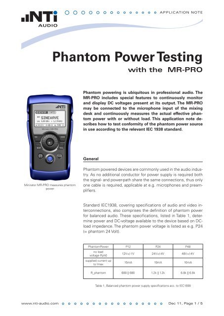
Phantom Power Testing
Phantom Power Testing
Phantom Power Testing

You also want an ePaper? Increase the reach of your titles
YUMPU automatically turns print PDFs into web optimized ePapers that Google loves.
Minirator MR-PRO measures phantom<br />
power<br />
www.nti-audio.com<br />
ApplicAtion note<br />
<strong>Phantom</strong> <strong>Power</strong> <strong>Testing</strong><br />
with the MR-PRO<br />
<strong>Phantom</strong> powering is ubiquitous in professional audio. The<br />
MR-PRO includes special features to continuously monitor<br />
and display DC voltages present at its output. The MR-PRO<br />
may be connected to the microphone input of the mixing<br />
desk and continuously measures the actual effective phantom<br />
power with or without load. This application note describes<br />
how to test conformity of the phantom power source<br />
in use according to the relevant IEC 1938 standard.<br />
General<br />
<strong>Phantom</strong> powered devices are commonly used in the audio industry.<br />
As no additional conductor for power supply is required both<br />
the signal- and power-path share the same connections, thus only<br />
one cable is required, applicable at e.g. microphones and preamplifiers.<br />
Standard IEC1938, covering specifications of audio and video interconnections,<br />
also comprises the definition of phantom power<br />
for balanced audio. These specifications, listed in Table 1, determine<br />
power and DC-voltage available to the device based on DCload<br />
impedance. The phantom power voltage is listed as e.g. P24<br />
(= phantom 24 Volt).<br />
<strong>Phantom</strong><strong>Power</strong> P12 P24 P48<br />
no load<br />
voltage Pph0<br />
supplied current up<br />
to Imax<br />
12V+/-1V 24V+/-4V 48V+/-4V<br />
15mA 10mA 10mA<br />
R_phantom 680 || 680 1.2k || 1.2k 6.8k || 6.8k<br />
Table 1, Balanced phantom power supply specifications acc. to IEC1938<br />
Dec 11, page 1 / 5
www.nti-audio.com<br />
ApplicAtion note<br />
Surprisingly often audio phantom power sources can be found not<br />
conforming to the standard. This can severely affect performance<br />
of connected devices. Giving some examples:<br />
• maximum sound pressure level available in the operating range<br />
of analog microphones may be lowered, if available output voltage<br />
is lower then to be expected from the standard<br />
• sensitivity of analog microphones may be changed, if phantom<br />
power impedance is incorrect<br />
• frequency response of analog microphones may break down at<br />
low frequencies if the microphones includes capacitive output<br />
coupling and phantom power impedance is lower then given in<br />
the standard<br />
• power hungry devices (as some digital microphones) might not<br />
even start to work<br />
• connecting of a P12 or P24 device to a non-standard impedance<br />
P48 may damage the device<br />
<strong>Phantom</strong><strong>Power</strong> P12 P24 P48<br />
Umin @ Imax 5.9V 14V 10V<br />
p_load @ Imax 88mW 140mW 100mW<br />
p_max @ Uph0<br />
nominal<br />
106mW 240mW 169mW<br />
I @ p_max 17.6mA 20mA 7mA<br />
Table 2, Characteristic phantom power supply parameters for R&D<br />
Besides others Table 2 lists the minimum voltage Umin @ Imax,<br />
which is available to the remote powered device. It can be measured<br />
at pin2 (or pin3) relative to pin1 if the maximum allowed current<br />
Imax is drawn and if voltage Uph0 (no load phantom voltage)<br />
is at its minimum specified value. In case the DC-impedances are<br />
matched between phantom power source and connected device,<br />
the maximum power will be available, thus DC-voltage at pin2 and<br />
pin3 will be just half the no load voltage Uph0.<br />
The available power is maximized for P24 and so recommended<br />
by the IEC for new designs. But still P48 is the most widespread<br />
phantom power voltage. This is due to the fact that using P48<br />
with analog microphones circuits allows for maximum available<br />
sound pressure level by less expensive circuits.<br />
page 2 / 5
<strong>Phantom</strong> power measurement with Minirator MR-PRO<br />
<strong>Phantom</strong> power screen<br />
Minirator MR-PRO<br />
How to qualify the phantom power source?<br />
www.nti-audio.com<br />
ApplicAtion note<br />
The MR-PRO displays the “DC” field continuously including the<br />
average voltage value of Pin 2 and Pin 3 of the connection. By<br />
moving the main cursor over the “DC” field, a popup panel appears<br />
showing the two individual phantom power voltages on pin<br />
2 and pin 3.<br />
MR-PRO Mixing desk<br />
V2<br />
V3<br />
2<br />
1<br />
3<br />
XLR<br />
+48V<br />
2 x 6.8kΩ<br />
Figure1, Schematics of a typical 48VDC phantom power supply<br />
<strong>Testing</strong> the phantom power source consists of two steps:<br />
• Measure phantom power voltage at “no load” condition<br />
• Measure phantom power voltage at Imax<br />
1. Measure phantom power voltage at “no load” condition<br />
Connect the MR-PRO to the audio input with a balanced XLR cable<br />
and switch the phantom power on.<br />
The displayed DC value will slightly differ from the no load voltage.<br />
This is due to the impedance of the MR-PRO which is necessary<br />
to discharge the output AC-coupling capacitor. Table 3 shows the<br />
range of displayed DC values (including measurement tolerances)<br />
for which Uph0 conforms to the standard.<br />
<strong>Phantom</strong><strong>Power</strong> P12 P24 P48<br />
max. Uph0 13.4V 28.6V 51.4V<br />
min. Uph0 10.4V 19.2V 40.9V<br />
Table 3, <strong>Phantom</strong> power voltage range meeting specifications at no load conditions<br />
measured by MR-PRO<br />
R2<br />
R3<br />
page 3 / 5
www.nti-audio.com<br />
2. Measure phantom power at Imax<br />
ApplicAtion note<br />
A defined load has to be connected to the phantom power source,<br />
thus drawing the maximum current Imax. For this purpose a test<br />
adapter may be applied. The test adapter shall be connected between<br />
the MR-PRO output and the phantom power output, as<br />
shown in the drawing below. With an additional Y-cable the MR-<br />
PRO monitors the phantom power supply during an actual microphone<br />
connected.<br />
6k8<br />
5mA<br />
6k8<br />
+48V ±4V<br />
10mA<br />
5mA<br />
DUT with P48<br />
3<br />
2<br />
1<br />
R3 R2<br />
Test Adapter<br />
Test Adapter simulating maximum load conditions<br />
MR-PRO<br />
The resistor values R2 and R3 for the defined NTI AGload<br />
are listed in<br />
Table 4. With these resistance values the DC-current will be Imax<br />
if Uph0 is at specified minimum.<br />
Date Name<br />
Designed: 19.02.08<br />
Drawn: 19.02.08<br />
Version 0000: 19.02.08<br />
Ben<br />
M. Lutz<br />
M. Lutz Project: MR-PRO<br />
Im alten Riet 102, FL-9494 Schaan, Liechtenstein<br />
Phone: 00423 239 60 60, www.nti-audio.com<br />
Version 0001:<br />
Version 0002:<br />
Version 0003:<br />
07.11.08 M. Lutz Title: App Note <strong>Phantom</strong> <strong>Power</strong><br />
PCB: --<br />
Part No:<br />
Sheet No: 1/1 Revision: 0001<br />
<strong>Phantom</strong><strong>Power</strong> P12 P24 P48<br />
R2 || R3 787 || 787 2.8k || 2.8k 2k || 2k<br />
Table 4, Test resistor values (R2, R3 see schematics)<br />
3<br />
2<br />
1<br />
page 4 / 5
www.nti-audio.com<br />
ApplicAtion note<br />
The following Table 5 shows the range of displayed DC values at<br />
loads according to Table 4 for which the phantom power source<br />
conforms to the standard. The table includes DC-measurement<br />
tolerances.<br />
<strong>Phantom</strong><strong>Power</strong> P12 P24 P48<br />
max. Uph0 7.2V 20.2V 12.2V<br />
min. Uph0 5.4V 13.5V 9.5V<br />
Table 5, <strong>Phantom</strong> power voltage range meeting specifications at max load conditions<br />
measured by MR-PRO<br />
Measurement at mixing desks with multiple phantom power supplies<br />
Conformity to the standard should be assured at maximum load<br />
at each phantom power input at e.g. mixing desks. The phantom<br />
power measurement shall be carried out as follows:<br />
• Enable all phantom powered outputs and load them with devices<br />
for simulation of the worst case conditions or alternatively<br />
insert the described test adapters at each output.<br />
• Measure the phantom power at each channel with the Minirator<br />
MR-PRO<br />
•<br />
Compare the test results with the values listed above<br />
page 5 / 5