VNA Frequency Extension Products - Gigacomp
VNA Frequency Extension Products - Gigacomp
VNA Frequency Extension Products - Gigacomp

You also want an ePaper? Increase the reach of your titles
YUMPU automatically turns print PDFs into web optimized ePapers that Google loves.
<strong>VNA</strong> <strong>Frequency</strong> <strong>Extension</strong> <strong>Products</strong><br />
F E A T U R E S<br />
A P P L I C A T I O N S<br />
D E S C R I P T I O N<br />
Light & easy to carry.<br />
3 foot mounting for optimum<br />
stability.<br />
Compact Robust Design.<br />
Excellent Dynamic range.<br />
Low Noise Level.<br />
Convection Cooled.<br />
Offers full capability to<br />
measure Active & Passive<br />
components using integrated<br />
Manual Attenuator<br />
Custom options available for<br />
Antenna Testing and other<br />
High Dynamic range<br />
requirements<br />
Test Equipment.<br />
Test Instrumentation.<br />
A C C E S S O R I E S<br />
Calibration Kit.<br />
Cables.<br />
Manuals.<br />
Flight case optional.<br />
Farran Technology Ltd offers frequency extension<br />
modules and frequency extension controller for Vector<br />
Network Analysers to extend their measurement<br />
capability to 110GHz.They are designed to cover<br />
4 waveguides bands:<br />
• U band ( 40GHz - 60GHz );<br />
• V band ( 50GHz - 75GHz );<br />
• E band ( 60GHz – 90GHz );<br />
• W band ( 75GHz – 110GHz)<br />
with ongoing development on higher frequency modules.<br />
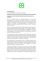
FEC-xx Controller Box<br />
FEV-xx-T/R Extender Head<br />
Calibration Kit
SPECIFICATION<br />
(F & D band are currently being developed)<br />
Waveguide<br />
designation<br />
U – band<br />
(WR-19)<br />
V – band<br />
(WR-15)<br />
E – band<br />
(WR-12)<br />
W – band<br />
(WR-10)<br />
F – band*<br />
(WR-8)<br />
D – band*<br />
(WR-6)<br />
Model Number<br />
FEV - 19<br />
FEV - 15<br />
FEV - 12<br />
FEV - 10<br />
FEV - 8<br />
FEV - 6<br />
<strong>Frequency</strong><br />
Range [GHz]<br />
40 - 60<br />
50 - 75<br />
60 - 90<br />
75 - 110<br />
90 - 140<br />
110 - 170<br />
RF <strong>Frequency</strong><br />
[GHz]<br />
10 - 15<br />
12.5 - 18.8<br />
10 - 15<br />
12.5 - 18.8<br />
11.25 - 17.5<br />
11 - 17<br />
RF Harmonic<br />
Number<br />
4<br />
LO <strong>Frequency</strong> + -<br />
IF<br />
offset<br />
10 - 15<br />
[GHz]<br />
4<br />
10 - 15<br />
6<br />
10 - 15<br />
6<br />
9.4 - 13.75<br />
8<br />
11.25 - 17.5<br />
10<br />
9.1 - 14.2<br />
LO Harmonic<br />
Number<br />
4<br />
5<br />
6<br />
8<br />
8<br />
12<br />
IF <strong>Frequency</strong><br />
[MHz]<br />
10 - 300<br />
10 - 300<br />
10 - 300<br />
10 - 300<br />
10 - 300<br />
10 - 300<br />
Dynamic Range<br />
[dB]<br />
>105<br />
>100<br />
>97<br />
>94<br />
>80<br />
70dB typ<br />
Power at DUT<br />
input [dBm] (typical)<br />
+7<br />
+5<br />
+2<br />
0<br />
-8<br />
-20<br />
SYSTEM OPERATION<br />
The Farran transmission/reflection module is driven by RF<br />
and LO signals from the compatible <strong>VNA</strong>, with mm-wave<br />
option. In the T/R module the RF signal is amplified,<br />
multiplied and applied to dual directional coupler. The<br />
through path of the coupler is connected to the test port<br />
and the signal is transmitted to DUT. A portion of the<br />
transmitted signal is coupled back to the harmonic mixer,<br />
driven by the LO. The mixing product is sent to REF IF<br />
output.<br />
The reflected signal from the DUT is coupled through the<br />
other coupled port of the coupler and used as a RF input for<br />
the second harmonic mixer, where Test IF signal is<br />
generated. The REF and TEST IF signals are compared in<br />
phase and amplitude in the <strong>VNA</strong> to produce results for S11.<br />
The transmitted signal through the DUT is received by the<br />
other module and is coupled to the harmonic mixer.<br />
This again is compared in phase and amplitude to the REF<br />
signal to produce results for S21. Similar scenario occurs in<br />
the other module of the pair, to produce results for S22 and<br />
S12, enabling quick and accurate full two port S-parameter<br />
measurement.<br />
In the configuration with T/R and T only forward transmission<br />
coefficient and input reflection coefficient can be<br />
measured simultaneously. To obtain a full two port<br />
S-parameter measurement the DUT is reversed in the next<br />
step and measurement repeated.<br />
C O N TA C T D E TA I L S :<br />
Unit 1, Airport East Business Park,<br />
Farmers Cross, Cork, Ireland.<br />
tel: (353) 21 484 9170<br />
fax: (353) 21 484 9192<br />
sales@farran.com<br />
www.farran.com