2004, 3D thermo-electric full cell and external busbar model - GeniSim
2004, 3D thermo-electric full cell and external busbar model - GeniSim
2004, 3D thermo-electric full cell and external busbar model - GeniSim

Create successful ePaper yourself
Turn your PDF publications into a flip-book with our unique Google optimized e-Paper software.
Using ANSYS <strong>and</strong> CFX to Model<br />
Aluminum Reduction Cell since1984<br />
<strong>and</strong> Beyond<br />
Dr. Marc<br />
Dupuis
1980-84, 2D potroom ventilation<br />
<strong>model</strong><br />
Physical<br />
<strong>model</strong>
1980-84, 2D potroom ventilation<br />
<strong>model</strong><br />
Experimental results<br />
Best <strong>model</strong> results<br />
The best results of my Ph.D. work: the 2D finite difference vorticity-stream<br />
function formulated <strong>model</strong> could not reproduces well the observed air flow<br />
regardless of the turbulence <strong>model</strong> used.
1984, <strong>3D</strong> <strong>thermo</strong>-<strong>electric</strong><br />
half anode <strong>model</strong><br />
That <strong>model</strong> was<br />
developed on<br />
ANSYS 4.1<br />
installed on a<br />
shaded VAX 780<br />
platform.<br />
That very first<br />
<strong>3D</strong> half anode<br />
<strong>model</strong> of around<br />
4000 Solid 69<br />
<strong>thermo</strong>-<strong>electric</strong><br />
elements took 2<br />
weeks elapse<br />
time to compute<br />
on the VAX.
1984, Instrumented Anode<br />
Setup
1986, <strong>3D</strong> <strong>thermo</strong>-<strong>electric</strong> cathode<br />
side slice <strong>and</strong> cathode corner <strong>model</strong><br />
The next step was<br />
the development<br />
of a <strong>3D</strong> cathode<br />
side slice <strong>thermo</strong><strong>electric</strong><br />
<strong>model</strong><br />
that included the<br />
calculation of the<br />
thickness of the<br />
solid electrolyte<br />
phase on the <strong>cell</strong><br />
side wall .<br />
Despite the very<br />
serious limitations<br />
on the size of the<br />
mesh, a <strong>full</strong><br />
cathode corner<br />
was built next .
Design of 2 high amperage <strong>cell</strong> cathodes<br />
1987: Apex 4 1989: A310<br />
Comparison of the predicted versus measured behavior was within 5%<br />
in both cases, demonstrating the value of the numerical tools developed.
1988, <strong>3D</strong> cathode potshell plastic<br />
deformation mechanical <strong>model</strong><br />
The new <strong>model</strong><br />
type addresses a<br />
different aspect<br />
of the physic of<br />
an aluminum<br />
reduction <strong>cell</strong>,<br />
namely the<br />
mechanical<br />
deformation of<br />
the cathode steel<br />
potshell under<br />
its thermal load<br />
<strong>and</strong> more<br />
importantly its<br />
internal<br />
pressure load .
1989, <strong>3D</strong> cathode potshell plastic deformation <strong>and</strong><br />
lining swelling mechanical <strong>model</strong><br />
First “Half Empty shell” potshell <strong>model</strong> developed in 1989<br />
<strong>and</strong> presented at a CRAY Supercomputing Symposium in<br />
1990
1992, <strong>3D</strong> <strong>thermo</strong>-<strong>electric</strong><br />
quarter cathode <strong>model</strong><br />
With the upgrade of<br />
the P-IRIS to 4D/35<br />
processor, <strong>and</strong> the<br />
option to run on a<br />
CRAY XMP<br />
supercomputer, the<br />
severe limitations on<br />
the CPU usage were<br />
finally partially<br />
lifted.<br />
This opened the door<br />
to the possibility to<br />
develop a <strong>full</strong> <strong>3D</strong><br />
<strong>thermo</strong>-<strong>electric</strong><br />
quarter cathode<br />
<strong>model</strong>.
1992, <strong>3D</strong> <strong>thermo</strong>-<strong>electric</strong> “pseudo” <strong>full</strong> <strong>cell</strong><br />
<strong>and</strong> <strong>external</strong> <strong>busbar</strong>s <strong>model</strong><br />
As a first step toward<br />
the development of a<br />
first <strong>thermo</strong>-electromagnetic<br />
<strong>model</strong>, a <strong>3D</strong><br />
<strong>thermo</strong>-<strong>electric</strong><br />
“pseudo” <strong>full</strong> <strong>cell</strong> <strong>and</strong><br />
<strong>external</strong> <strong>busbar</strong>s<br />
<strong>model</strong> was developed.<br />
That <strong>model</strong> was really<br />
at the limit of what<br />
could be built <strong>and</strong><br />
solved on the<br />
available hardware at<br />
the time both in terms<br />
of RAM memory <strong>and</strong><br />
disk space storage.
1992, <strong>3D</strong> cathode potshell plastic deformation<br />
<strong>and</strong> lining swelling mechanical <strong>model</strong><br />
The empty quarter<br />
potshell mechanical<br />
<strong>model</strong> was extended<br />
to take into account<br />
the coupled<br />
mechanical response<br />
of the swelling lining<br />
<strong>and</strong> the restraining<br />
potshell structure.<br />
That coupling was<br />
important to consider<br />
as a stiffer, more<br />
restraining potshell<br />
will face more<br />
internal pressure<br />
from the swelling<br />
lining material.
1992, <strong>3D</strong> cathode potshell plastic deformation<br />
<strong>and</strong> lining swelling mechanical <strong>model</strong><br />
Elastic mode<br />
A numerical<br />
scheme <strong>external</strong> to<br />
the ANSYS solver<br />
must be setup,<br />
starting from an<br />
assumed initial<br />
internal load. The<br />
task of that<br />
<strong>external</strong> numerical<br />
scheme is to<br />
converge toward<br />
that cathode block<br />
equilibrium<br />
condition pressure<br />
loading for each<br />
element face of the<br />
carbon block/side<br />
lining interface.
1992, <strong>3D</strong> cathode potshell plastic deformation<br />
<strong>and</strong> lining swelling mechanical <strong>model</strong>
1993, <strong>3D</strong> electro-magnetic <strong>full</strong> <strong>cell</strong> <strong>model</strong><br />
The development of<br />
a finite element<br />
based aluminum<br />
reduction <strong>cell</strong><br />
magnetic <strong>model</strong><br />
clearly represented<br />
a third front of<br />
<strong>model</strong> development.<br />
Because of the<br />
presence of the<br />
ferro-magnetic<br />
shielding structure,<br />
the solution of the<br />
magnetic problem<br />
cannot be reduced<br />
to a simple Biot-<br />
Savard integration<br />
scheme.
1993, <strong>3D</strong> electro-magnetic <strong>full</strong> <strong>cell</strong> <strong>model</strong>
1993, <strong>3D</strong> electro-magnetic <strong>full</strong> <strong>cell</strong> <strong>model</strong>
1993, <strong>3D</strong> transient <strong>thermo</strong>-<strong>electric</strong><br />
<strong>full</strong> quarter <strong>cell</strong> preheat <strong>model</strong><br />
The cathode quarter<br />
<strong>thermo</strong>-<strong>electric</strong> <strong>model</strong><br />
was extended into a<br />
<strong>full</strong> quarter <strong>cell</strong><br />
geometry in preheat<br />
configuration <strong>and</strong> ran<br />
in transient mode in<br />
order to analyze the<br />
<strong>cell</strong> preheat process .<br />
The need was urgent,<br />
but due to its huge<br />
computing resources<br />
requirements, the<br />
<strong>model</strong> was not ready in<br />
time to be used to solve<br />
the plant problem at<br />
the time.
1993’s Model Extension to Stress Analysis<br />
Equivalent stress in the cathode panel at 36 hours – st<strong>and</strong>ard coke bed
1993, 2D CFDS-Flow<strong>3D</strong><br />
potroom ventilation <strong>model</strong>
1993, 2D CFDS-Flow<strong>3D</strong><br />
potroom ventilation <strong>model</strong><br />
2D “Reynolds flux” <strong>model</strong> results vs. physical <strong>model</strong> results
1998, <strong>3D</strong> <strong>thermo</strong>-<strong>electric</strong><br />
<strong>full</strong> <strong>cell</strong> slice <strong>model</strong><br />
As described previously,<br />
the <strong>3D</strong> half anode <strong>model</strong><br />
<strong>and</strong> the <strong>3D</strong> cathode side<br />
slice <strong>model</strong> have been<br />
developed in sequence,<br />
<strong>and</strong> each separately<br />
required a fair amount of<br />
computer resources.<br />
Merging them together<br />
was clearly not an option<br />
at the time, yet it would<br />
have been a natural thing<br />
to do. Many years later,<br />
the hardware limitation<br />
no longer existed so they<br />
were finally merged.
1998, 2D+ <strong>thermo</strong>-<strong>electric</strong><br />
<strong>full</strong> <strong>cell</strong> slice <strong>model</strong><br />
2D+ version of the same<br />
<strong>full</strong> <strong>cell</strong> slice <strong>model</strong> was<br />
developed. Solving a<br />
truly three dimensional<br />
<strong>cell</strong> slice geometry using<br />
a 2D <strong>model</strong> may sound<br />
like a step in the wrong<br />
direction, but depending<br />
on the objective of the<br />
simulation, sometimes it<br />
is not so.<br />
The 2D+ <strong>model</strong> uses beam<br />
elements to represent<br />
geometric features lying<br />
in the third dimension<br />
(the + in the 2D+ <strong>model</strong>).
1999, 2D+ transient <strong>thermo</strong>-<strong>electric</strong><br />
<strong>full</strong> <strong>cell</strong> slice <strong>model</strong><br />
An interesting feature of<br />
that <strong>model</strong> is the<br />
extensive APDL coding<br />
that computes other<br />
aspects of the process<br />
related to the different<br />
mass balances like the<br />
alumina dissolution, the<br />
metal production etc.<br />
As that type of <strong>model</strong><br />
has to compute the<br />
dynamic evolution of the<br />
ledge thickness, there is<br />
a lot more involved than<br />
simply activating the<br />
ANSYS transient mode<br />
option.
2000, <strong>3D</strong> <strong>thermo</strong>-<strong>electric</strong><br />
cathode slice erosion <strong>model</strong><br />
Cathode erosion rate is<br />
proportional to the<br />
cathode surface current<br />
density <strong>and</strong> that the<br />
initial surface current<br />
density is not uniform,<br />
the erosion profile will<br />
not be uniform.<br />
Fur<strong>thermo</strong>re, that initial<br />
erosion profile will<br />
promote further local<br />
concentration of the<br />
surface current density<br />
that in turn will promote<br />
a further intensification<br />
of the non-uniformity of<br />
the erosion rate.
Base Case Model Solution<br />
Erosion profile animation of the<br />
base<br />
case <strong>model</strong> for the first 2 years
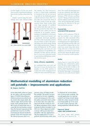
2001, <strong>3D</strong> CFX-4 potroom ventilation <strong>model</strong><br />
Streak lines
2001, <strong>3D</strong> CFX-4 potroom ventilation <strong>model</strong><br />
Temperature<br />
fringe plot,<br />
back plane
2002, <strong>3D</strong> <strong>thermo</strong>-<strong>electric</strong> half cathode<br />
<strong>and</strong> <strong>external</strong> <strong>busbar</strong> <strong>model</strong><br />
Temperature<br />
Busbars<br />
Voltage Drop
Relationship between Local Heat Transfer<br />
Coefficient of the Liquid/Ledge Interface <strong>and</strong><br />
the Velocity Field<br />
Heat Transfer<br />
Coefficients:<br />
with ± 20% modulation
2002, <strong>3D</strong> <strong>thermo</strong>-<strong>electric</strong> half cathode<br />
<strong>and</strong> <strong>external</strong> <strong>busbar</strong> <strong>model</strong><br />
Voltage Drop<br />
in Metal
2003, <strong>3D</strong> <strong>thermo</strong>-<strong>electric</strong> <strong>full</strong> cathode<br />
<strong>and</strong> <strong>external</strong> <strong>busbar</strong> <strong>model</strong><br />
A P4 3.2 GHz computer<br />
took 16.97 CPU hours to<br />
build <strong>and</strong> solve that <strong>model</strong>
2003, <strong>3D</strong> <strong>thermo</strong>-<strong>electric</strong> <strong>full</strong> cathode<br />
<strong>and</strong> <strong>external</strong> <strong>busbar</strong> <strong>model</strong><br />
Voltage drop in<br />
metal pad: 5 mV<br />
Current density in metal pad
<strong>2004</strong>, <strong>3D</strong> <strong>thermo</strong>-<strong>electric</strong> <strong>full</strong> <strong>cell</strong><br />
<strong>and</strong> <strong>external</strong> <strong>busbar</strong> <strong>model</strong><br />
Initial 585,016<br />
elements mesh<br />
Coarser 329,288<br />
elements mesh
<strong>2004</strong>, <strong>3D</strong> <strong>thermo</strong>-<strong>electric</strong> <strong>full</strong> <strong>cell</strong><br />
<strong>and</strong> <strong>external</strong> <strong>busbar</strong> <strong>model</strong><br />
A P4 3.2 GHz<br />
computer took 26.1<br />
CPU hours to build<br />
<strong>and</strong> solve that <strong>model</strong>
Thermo-Electric Design of a 740 kA Cell,<br />
Is There a Size Limit?<br />
Thermo-Electric Design of a 740 kA Cell Using a<br />
Complete Full Cell Quarter Thermo-Electric Model
<strong>2004</strong>, <strong>3D</strong> <strong>thermo</strong>-<strong>electric</strong> <strong>full</strong> <strong>cell</strong><br />
<strong>and</strong> <strong>external</strong> <strong>busbar</strong> erosion <strong>model</strong><br />
Once the geometry of<br />
the ledge is<br />
converged, a new<br />
iteration loop start,<br />
this time to simulate<br />
the erosion of the<br />
cathode block as<br />
function of the<br />
surface current<br />
density
2005 Weakly coupled <strong>3D</strong> <strong>thermo</strong>-<strong>electric</strong> <strong>full</strong><br />
<strong>cell</strong> <strong>and</strong> <strong>external</strong> <strong>busbar</strong> <strong>and</strong> MHD <strong>model</strong>
First Weakly Coupled Solution Between<br />
Thermo-Electric <strong>and</strong> MHD Models: 500 kA Cell Design<br />
Velocity fields <strong>and</strong> turbulent effective viscosity<br />
distribution in liquid aluminium for the 500 kA <strong>cell</strong> as<br />
predicted by the MHD <strong>model</strong>
First Weakly Coupled Solution Between<br />
Thermo-Electric <strong>and</strong> MHD Models: 500 kA Cell Design<br />
Setup of the local heat transfer<br />
coefficients at the liquids/ledge<br />
interface based on the velocity<br />
fields calculated by the MHD <strong>model</strong><br />
h metal/ledge (W/m2K)<br />
= 1684 + 2000 V ½ (m/s)<br />
h bath/ledge (W/m2K)<br />
= 1121 + 2000 V ½ (m/s)
First Weakly Coupled Solution Between<br />
Thermo-Electric <strong>and</strong> MHD Models: 500 kA Cell Design<br />
The obtained ledge<br />
profile geometry is<br />
transferred to the<br />
MHD <strong>model</strong> <strong>and</strong> the<br />
MHD <strong>cell</strong> stability<br />
analysis is computed<br />
again
2006 Weakly coupled <strong>3D</strong> <strong>thermo</strong>-<strong>electric</strong> <strong>full</strong><br />
<strong>cell</strong> <strong>model</strong> <strong>and</strong> mechanical quarter <strong>cell</strong> <strong>model</strong>
2006 Weakly coupled <strong>3D</strong> <strong>thermo</strong>-<strong>electric</strong> <strong>full</strong><br />
<strong>cell</strong> <strong>model</strong> <strong>and</strong> mechanical quarter <strong>cell</strong> <strong>model</strong><br />
Temperature Loading for the Fine<br />
Mesh Model
2006 Weakly coupled <strong>3D</strong> <strong>thermo</strong>-<strong>electric</strong> <strong>full</strong><br />
<strong>cell</strong> <strong>model</strong> <strong>and</strong> mechanical quarter <strong>cell</strong> <strong>model</strong><br />
Relative Vertical Displacement for the Fine<br />
Mesh Model
500 kA Cell Mechanical Model Results<br />
Base Case.<br />
With<br />
Cooling<br />
Fins.<br />
With Forced-<br />
Air Cooling.<br />
Temperature distribution for the studied 500 kA <strong>cell</strong><br />
configurations.
500 kA Cell Mechanical Model Results<br />
Comparison of the relative vertical displacement on the long axis of<br />
the 500 kA <strong>cell</strong>.
2007 Weakly coupled <strong>thermo</strong>-electromechanical<br />
<strong>model</strong> <strong>and</strong> magneto-hydrodynamic<br />
<strong>full</strong> <strong>cell</strong> <strong>and</strong> <strong>external</strong> <strong>busbar</strong> <strong>model</strong>
2009, “Half Empty Shell” Potshell Model<br />
Plastic mode:<br />
Total displacement<br />
(m)<br />
Took 103842 CPU seconds or 1.2 CPU days which is 3.8 times more than what was required to solve the “almost empty<br />
shell” potshell <strong>model</strong>.
2009, “ Improved Half Empty Shell” Potshell Model<br />
Plastic mode: potshell total<br />
displacement (m)
2010, Thermo-Electro-Mechanical<br />
Anode Stub Hole Model<br />
Voltage<br />
(V)<br />
Current<br />
Density<br />
(A/m 2 )<br />
Pressure <strong>and</strong> temperature dependent contact resistance<br />
<strong>model</strong> results
2010, Thermo-Electro-Mechanical<br />
Anode Stub Hole Model<br />
Contact<br />
pressure<br />
(MPa)<br />
Pressure <strong>and</strong> temperature dependent contact resistance<br />
<strong>model</strong> results
2010, Thermo-Electro-Mechanical<br />
Anode Stub Hole Model<br />
Voltage (V)<br />
Horizontal voltage 40 mm under the anode carbon surface<br />
Distance from stud centerline (m)<br />
Instrumented Anode:<br />
Anode Stud Voltage Drop Comparison
H<br />
y (m)<br />
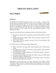
Currently, we can fit Hall-Héroult mathematical <strong>model</strong>s<br />
into three broad categories:<br />
• Stress <strong>model</strong>s which are<br />
generally associated with<br />
<strong>cell</strong> shell deformation <strong>and</strong><br />
cathode heaving issues.<br />
Future developments<br />
• Magneto-hydro-dynamic<br />
(MHD) <strong>model</strong>s which are<br />
generally associated with<br />
the problem of <strong>cell</strong> stability.<br />
• Thermal-<strong>electric</strong> <strong>model</strong>s<br />
which are generally<br />
associated with the<br />
problem of <strong>cell</strong> heat<br />
balance.<br />
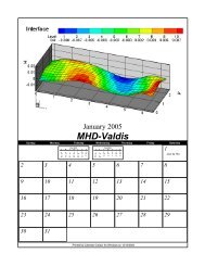
Interface<br />
0.02<br />
0.01<br />
0<br />
-0.01<br />
0<br />
Z<br />
Y<br />
X<br />
Level<br />
DH:<br />
1<br />
1<br />
-0.008<br />
2<br />
2<br />
-0.007<br />
3<br />
-0.005<br />
3<br />
4<br />
-0.003<br />
4<br />
5<br />
-0.002<br />
6<br />
-0.000<br />
5<br />
7<br />
0.002<br />
6<br />
8<br />
0.003<br />
X<br />
0<br />
9<br />
0.005<br />
1<br />
2<br />
10<br />
0.007<br />
Y<br />
2<br />
1<br />
0<br />
Velocity field in Al<br />
0.10 m/s<br />
0 1 2 3 4 5 6<br />
x (m)<br />
Cell<br />
Design
Future developments<br />
Yet, to be rigorous, a fusion of those three types of <strong>model</strong> into a <strong>full</strong>y<br />
coupled multi-physics finite element <strong>model</strong> is required because:<br />
• MHD is affected by the ledge profile, mostly dictated by the <strong>cell</strong> heat<br />
balance design.<br />
• local ledge profile is affected by the metal recirculation pattern mostly<br />
dictated by the <strong>busbar</strong>s MHD design .<br />
• shell deformation is strongly influenced by the shell thermal gradient<br />
controlled by the <strong>cell</strong> heat balance design.<br />
• steel shell structural elements like cradles <strong>and</strong> stiffeners influence the<br />
MHD design through their magnetic shielding property.<br />
• global shell deformation affects the local metal pad height, which in<br />
turn affects both the <strong>cell</strong> heat balance <strong>and</strong> <strong>cell</strong> stability
<strong>3D</strong> <strong>full</strong>y coupled <strong>thermo</strong>-electro-mechanicomagneto-hydro-dynamic<br />
<strong>full</strong> <strong>cell</strong> <strong>and</strong><br />
<strong>external</strong> <strong>busbar</strong> <strong>model</strong> weakly coupled with<br />
a <strong>3D</strong> potroom ventilation <strong>model</strong>