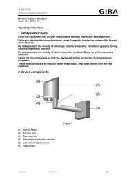
1 Safety instructions 2 Device components KNX/EIB - Gira
1 Safety instructions 2 Device components KNX/EIB - Gira
1 Safety instructions 2 Device components KNX/EIB - Gira

Create successful ePaper yourself
Turn your PDF publications into a flip-book with our unique Google optimized e-Paper software.
<strong>KNX</strong>/<strong>EIB</strong><br />
Power supply<br />
Power supply 320 mA<br />
Order-No. : 1086 00<br />
Power supply 640 mA<br />
Order-No. : 1087 00<br />
Operating <strong>instructions</strong><br />
1 <strong>Safety</strong> <strong>instructions</strong><br />
Electrical equipment may only be installed and fitted by electrically skilled persons.<br />
Failure to observe the <strong>instructions</strong> may cause damage to the device and result in fire and<br />
other hazards.<br />
These <strong>instructions</strong> are an integral part of the product, and must remain with the end<br />
customer.<br />
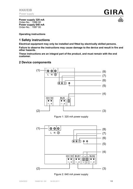
2 <strong>Device</strong> <strong>components</strong><br />
Figure 1: 320 mA power supply<br />
Figure 2: 640 mA power supply<br />
32543222 10499130 I00 04.05.2011<br />
1/5
<strong>KNX</strong>/<strong>EIB</strong><br />
Power supply<br />
(1) Connection of mains<br />
(2) Output DC 30 V<br />
(3) Outputs for bus lines<br />
(4) Reset switch for bus lines<br />
(5) LED display, red: bus reset<br />
(6) LED display, yellow: overvoltage<br />
(7) LED display, red: overload<br />
(8) LED display, green: operation<br />
3 Function<br />
System information<br />
This device is a product of the <strong>KNX</strong> system and complies with the <strong>KNX</strong> directives. Detailed<br />
technical knowledge obtained in <strong>KNX</strong> training courses is a prerequisite to proper<br />
understanding.<br />
Intended use<br />
- Supplying <strong>KNX</strong> devices with bus voltage<br />
- Mounting on DIN rail according to EN 60715 in distribution boxes<br />
Product characteristics<br />
- One or two outputs with integrated throttle for supplying bus lines<br />
- One DC 30 V output for supplying additional devices<br />
- Nominal voltage can be subdivided to outputs as desired<br />
- Reset switch for each bus line<br />
- Short-circuit proof<br />
- Overvoltage proof<br />
320 mA power supply (Figure 1):<br />
- An output with integrated throttle for supplying a bus line<br />
640 mA power supply (Figure 2):<br />
- Two outputs with integrated throttle for supplying bus lines<br />
4 Information for electrically skilled persons<br />
4.1 Fitting and electrical connection<br />
DANGER!<br />
Electrical shock when live parts are touched.<br />
Electrical shocks can be fatal.<br />
Before working on the device, disconnect the power supply and cover up live<br />
parts in the working environment.<br />
Fitting the device<br />
Observe the temperature range. Ensure sufficient cooling.<br />
o Mount the device on DIN rail. The terminals for the mains connection (1) must be at the<br />
top.<br />
Connecting the device<br />
o Connecting the mains voltage to the terminals L and N (1).<br />
o Connect the protective conductor PE to the terminal /.<br />
o Connect <strong>KNX</strong> bus line to a BUS output.<br />
i The total load of the outputs can be subdivided as desired. Do not exceed the total rated<br />
current (see chapter 5.1. Technical data).<br />
32543222 10499130 I00 04.05.2011 2/5
<strong>KNX</strong>/<strong>EIB</strong><br />
Power supply<br />
i A <strong>KNX</strong> bus line can be supplied from two power supply units. There must be at least 200 m<br />
of bus line between the infeed points.<br />
Installing the cover<br />
Figure 3<br />
Install the cover on all of the output terminals to protect the bus connection against hazardous<br />
voltages in the connection area.<br />
o Route the bus cable towards the rear.<br />
o Install cover on top of the connection terminal so that it snaps into place.<br />
Removing the cover<br />
o Press the cover to the side and pull it off.<br />
5 Appendix<br />
5.1 Technical data<br />
Rated voltage AC AC 161 ... 264 V ~<br />
Mains frequency<br />
50 / 60 Hz<br />
Rated voltage DC<br />
DC 176 ... 270 V<br />
Power loss<br />
max. 5 W (in rated operation)<br />
Output current<br />
Order-No. 1086 00<br />
320 mA (all outputs)<br />
Order-No. 1087 00<br />
640 mA (all outputs)<br />
Bus outputs<br />
Bus output voltage<br />
DC 28 ... 31 V SELV<br />
Connection type for bus<br />
Connection terminal<br />
<strong>KNX</strong> medium TP 1<br />
Output DC 30 V<br />
Output voltage<br />
DC 30 V<br />
Connection mode<br />
Connection terminal<br />
Ambient temperature -5 ... +45 °C<br />
Storage/transport temperature -25 ... +70 °C<br />
Fitting width<br />
Order-No. 1086 00<br />
Order-No. 1087 00<br />
Connection mode<br />
Single stranded<br />
finely stranded without conductor sleeve<br />
72 mm / 4 modules<br />
126 mm / 7 modules<br />
32543222 10499130 I00 04.05.2011 3/5<br />
Screw terminal<br />
0.2 ... 4 mm²<br />
0.75 ... 4 mm²
<strong>KNX</strong>/<strong>EIB</strong><br />
Power supply<br />
finely stranded with conductor sleeve<br />
5.2 Troubleshooting<br />
0.5 ... 2.5 mm²<br />
LED Überlast (7) lights up red<br />
Short-circuit on bus line.<br />
Eliminate short-circuit.<br />
The bus line is supplied by an additional power supply whose reset switch has been actuated.<br />
Eliminate reset.<br />
30 V DC output loaded too much.<br />
Reduce load, if necessary supply from another location.<br />
Too many devices connected to the bus line(s).<br />
Reduce number of devices. Check <strong>KNX</strong> topology. Connect devices to a different bus line.<br />
Found a new bus line if necessary.<br />
If possible: connect a second power supply to the bus line.<br />
i There must be at least 200 m of bus line between the infeed points.<br />
LED Überspannung (6) lights up yellow<br />
Bus voltage too high, > 32 V DC.<br />
Switch device off.<br />
Determine cause, e.g. an additional, third-party power supply is connected, and eliminated<br />
it.<br />
LED Reset (5) lights up red, no communication to bus<br />
The reset switch for the corresponding bus line has been actuated, the bus line is shortcircuited.<br />
Switch-over reset switch (4).<br />
i Use suitable screwdriver for actuation.<br />
<strong>KNX</strong> device on bus line must be reset<br />
Disconnect device from bus line.<br />
– or –<br />
Press reset switch (4) on power supply. Actuation time min. 20 seconds. Then switch-over<br />
the reset switch again.<br />
i Use suitable screwdriver for actuation. During the reset state the associated LED (5) lights<br />
up red. Other power supplies connected to this bus line indicate overload during this time.<br />
LED operation (8) doe not light up, bus voltage has failed<br />
Mains voltage has failed.<br />
Check mains voltage. Switch on mains voltage/miniature circuit-breaker.<br />
5.3 Warranty<br />
The warranty is provided in accordance with statutory requirements via the specialist trade.<br />
Please submit or send faulty devices postage paid together with an error description to your<br />
responsible salesperson (specialist trade/installation company/electrical specialist trade). They<br />
will forward the devices to the <strong>Gira</strong> Service Center.<br />
32543222 10499130 I00 04.05.2011 4/5
<strong>KNX</strong>/<strong>EIB</strong><br />
Power supply<br />
<strong>Gira</strong><br />
Giersiepen GmbH & Co. KG<br />
Elektro-Installations-<br />
Systeme<br />
Industriegebiet Mermbach<br />
Dahlienstraße<br />
42477 Radevormwald<br />
Postfach 12 20<br />
42461 Radevormwald<br />
Deutschland<br />
Tel +49(0)21 95 - 602-0<br />
Fax +49(0)21 95 - 602-399<br />
www.gira.de<br />
info@gira.de<br />
32543222 10499130 I00 04.05.2011 5/5