Measuring Device - GLÖTZL Gesellschaft für Baumesstechnik mbH
Measuring Device - GLÖTZL Gesellschaft für Baumesstechnik mbH
Measuring Device - GLÖTZL Gesellschaft für Baumesstechnik mbH

You also want an ePaper? Increase the reach of your titles
YUMPU automatically turns print PDFs into web optimized ePapers that Google loves.
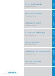
MOBILE MEASUREMENT SYSTEMS<br />
MOBILE MEASUREMENT<br />
SYSTEMS<br />
INSTALLATION MATERIAL<br />
INSTALLATION MATERIAL<br />
SPECIAL DEVICE CONSTRUCTION<br />
SPECIAL DEVICE<br />
CONSTRUCTION<br />
RECORDING SYSTEMS<br />
SOFTWARE AND SERVERS<br />
DISPLAY DEVICES<br />
GEODETIC EQUIPMENT<br />
GEODETIC EQUIPMENT DISPLAY DEVICES SOFTWARE AND SERVERS RECORDING SYSTEMS<br />
Advanced Solutions
MOBILE MEASUREMENT SYSTEMS<br />
MOBILE MEASUREMENT<br />
SYSTEMS<br />
Line, Measurement and Storage<br />
<strong>Device</strong> NMA 9 ><br />
Inclinometer NMGD ><br />
Inclinometer NMGH ><br />
Compass Probe ><br />
Dipmeter Standard ><br />
Inclinometer Interface NDI ><br />
Cable Reel NMK2 ><br />
Guide Bar ><br />
Push Equipment ><br />
Bore Hole Length <strong>Measuring</strong> Probe ><br />
<strong>Measuring</strong> Tubes for Borehole Length<br />
<strong>Measuring</strong> Probe ><br />
Borehole Modular Probe ><br />
Borehole Modular Probe - Calibre Modulus ><br />
Borehole Modular Probe - Lateral View<br />
Adapter ><br />
Borehole Modular Probe - Video Module ><br />
Hydrostatic Profi le Gauge HPG ><br />
Advanced Solutions<br />
< back to product type overview
NMA 9<br />
Line, measurement and storage device<br />
Art. No. 074.20<br />
The NMA 9 is used to log line measurement programmes, such as those used in an NMG inclinometer or an HPG hydrostatic<br />
settlement meter. With this device you can log analogue and digital sensors from <strong>GLÖTZL</strong> without the need of a connection to<br />
the power grid. The main benefits of this device are its easy handling and outstanding robustness for everyday use on the building<br />
site and the fact that it is so simple and easy to operate. The NMA 9 has a measuring point management system that clearly<br />
identifies individual measurements. When measurements have been completed, the memory is read out via our GLNP PC software<br />
and the measured values are displayed and evaluated graphically.<br />
Functions<br />
The following measuring devices can be<br />
connected:<br />
- NMG analogue probe vertical<br />
- NMGH analogue probe, horizontal<br />
- NMG D digital probe, vertical<br />
- NMGH D digital probe, horizontal with temp.<br />
- HPG (hydrostatic settlement meter)<br />
Supported measurement sequences:<br />
- 1-0 1-0<br />
- 0-1 0-1<br />
- 0-1 1-0<br />
- 1-0 0-1<br />
- 1-0<br />
- 0-1<br />
- 0-11-0 0-11-0 SNCF*<br />
Supported probe lengths:<br />
0.5 m, 1.0 m, 2.0 m, 3.0 m, 4.0 m, 5.0 m, 10.0 m<br />
Depth: 1 - maximum 999.5 m<br />
Accessories<br />
Leather bag<br />
Transfer cable NMA-PC<br />
Battery charging cable 12 V with car plug<br />
Grid charging cable<br />
*(only for inclinometer)<br />
Technical specifications:<br />
Data transfer:<br />
Language:<br />
Data memory:<br />
AD conversion:<br />
Display:<br />
Protection type:<br />
Dimensions (mm)<br />
Weight:<br />
Power supply:<br />
Power consumption at 230V/50Hz:<br />
Resolution NMG / NMGD:<br />
Resolution HPG:<br />
Temperature range:<br />
Batteries:<br />
Battery life:<br />
Charging time:<br />
Extras<br />
Battery display<br />
Display of difference error<br />
Internal clock and calendar<br />
Direct measurement for all probe/HPG types<br />
Display of remaining memory<br />
9600 or 38400 baud<br />
German, French, English<br />
for 100 measurement series<br />
16 bits<br />
2x20 characters illuminated<br />
IP65 (spray water)<br />
175x115x140 (LxWxH)<br />
2.2 kg<br />
5 x 1.2 V / 4500 mAh NiMh batteries<br />
0.1 A<br />
0.0001 (sin)<br />
either cm or mm<br />
-5 to +45°C<br />
NiMh integrated<br />
min. 9 hours in continuous operation<br />
3 hours<br />
Version 1/ Stand 31.05.2010/ P 074.20 NMA 9 en.pdf
Version: 05.04.2006 / IG / SP / P075.02.01.00.00.001R03_engl.doc<br />
<strong>GLÖTZL</strong> Baumeßtechnik<br />
DIGITAL - VERTICAL - INCLINOMETER<br />
Digital Probe - NMGD<br />
• Latest technology with micro-controlling<br />
• Approved and robust mechanics<br />
• Installed controller/AD-converter with<br />
16-Bit resolution ± 32.000<br />
• Digital data transfer without disturbances<br />
via serial interface 1 mA<br />
• Reliable measured data transfer for<br />
1.000 m<br />
• Real-value measuring data by correction<br />
and calculation of raw values in the<br />
controller<br />
• Measured values registration with each<br />
PC-Laptop, notebock a.s.o.<br />
• Simple calibration of probe, probe history<br />
stored in EEProm<br />
• Low costs for standard model<br />
• Probe secured against foreign use by<br />
pass-code, also in case of loss<br />
Type: NMGD<br />
Art. No: 75.02.01<br />
P075SB03.vsd<br />
Deviation<br />
α<br />
Guide tube<br />
Probe<br />
length<br />
l.<br />
<strong>Measuring</strong> Principle<br />
The analog measuring values of sensors<br />
are digitally converted, calculated and<br />
balanced in the probe by controller.<br />
Incorrect transfers are immediately<br />
recognized and definitely identified.<br />
With the probe, the guide tube is passed<br />
through step by step from the bottom to<br />
the top. In each measuring step the<br />
probe is recording the inclination angle<br />
between vertical and probe position in<br />
one or two measuring levels (A- resp.<br />
A+B-axes). The output at the readout unit<br />
is either done as sine of the inclination<br />
angle or as horizontal deviation<br />
(mm/step). For a higher measuring<br />
accuracy and to avoid measuring errors,<br />
an additional turnover measurement<br />
should be carried out with probe turned<br />
by 180°.<br />
Application Ranges<br />
• Stability control of skid-endangered slopes,<br />
constructions, retaining dams and<br />
embankments<br />
• Deformation measurements at excavation<br />
walls, besides tunnel tubes, in bore piles<br />
• Borehole measurements<br />
• Verticality proof of diaphragm walls<br />
• Stationary inclinometer chains
Version: 05.04.2006 / IG / SP / P075.02.01.00.00.001R03_engl.doc<br />
<strong>Measuring</strong> and Evaluation Possibilities of Digital Probe<br />
Cable reel<br />
NDI 12<br />
Laptop with GLNP<br />
Software<br />
Digital-Inclinometer<br />
VMG 14.1<br />
Messaufbau_NDI12a.vsd<br />
Digital Inclinometer Probe<br />
• Weight<br />
2.4 kgs, Ø 30 mm<br />
• Length<br />
0.5 or 1.0 m<br />
• <strong>Measuring</strong> range ± 30°, max. ± 60°<br />
• Linearity<br />
± 0.02 % f.s.<br />
• Temperature range -5 up to +60 °C<br />
• Guide tube max. Ø 75 mm, min. 35 mm<br />
• Resolution 0.02 mm up to max. 30°<br />
• Hysteresis<br />
0.001 % f.s.<br />
• Zero point deviation ± 0.005 % f.s./°C<br />
75.02.01 Probe NMGD 30/2 with 2 meas. axes<br />
75.02.00.01 NMV 0,5 elongation to 1 m meas.<br />
length, dismountable<br />
Multimeter VMG 14.1<br />
• Intelligent 4-channel readout unit<br />
• Menu guidance for selection of all common<br />
sensors<br />
• Serial measuring input for digital probe<br />
• Output interface serial V24<br />
• Installed accumulator and charger<br />
• Splash-proof, robust housing<br />
• Only one measuring instrument is required for a<br />
wide range of measuring jobs<br />
74.12.11 Standard model VMG 14.1<br />
Converter and Supply Unit NDI 12<br />
Installed battery with charger and charge control;<br />
converter for probe; battery buffering for Laptop<br />
12 V<br />
75.10.13 Converter and supply unit
<strong>Measuring</strong> Cable<br />
The measuring cable is supplied on a cable reel for<br />
max. 100 resp. 200 m cable with Kevlar core and<br />
with a watertight, corrosion-resistant plug connector<br />
with strain relief for probe connection.The measuring<br />
cable is made of PUR/PVG, Ø 10 mm, 6-core,<br />
marking each 0.5 m, weight 150 g/m.<br />
75.15.02 Cable reel NMK 2-50 with 50 m cable<br />
75.15.03 Cable reel NMK 2-100 with 100 m<br />
cable<br />
Larger lengths and special models on request.<br />
Version: 22.04.2005 / IG / SP / P075.02.01.00.00.001R03_engl.doc<br />
Inclination measurements and evaluations on<br />
client’s request are carried out at short notice by<br />
our experienced staff. For measuring applications,<br />
we are also prepared to deliver our equipment for<br />
hire.<br />
Inclinometer <strong>Measuring</strong> Tubes<br />
76.01.01 Inclinometer tube of aluminium,<br />
length 3 m, Ø 48/53 mm<br />
76.01.11 Connection piece of aluminium,<br />
length 300 mm, Ø 53/57 mm<br />
76.01.21 End cap to beat in V 48<br />
76.01.22 End cap KV 48<br />
76.01.23 End cap plug stopper SV 48<br />
76.01.24 End piece with lock SSV 53<br />
76.02.11 Inclinometer tube of ABS,<br />
length 3 m, Ø 49/55 mm<br />
76.02.13 Connection piece of ABS,<br />
length 300 mm, Ø 56/63 mm<br />
76.02.21 End cap to beat in PV 48<br />
76.02.22 End cap KV 51<br />
76.02.23 End cap plug stopper SV 48<br />
76.02.24 End piece with lock SSV 55<br />
Accessories<br />
75.20.01.51 Transport case of aluminium for 0.5 m<br />
probe, readout unit and cable reel<br />
75.20.11.01 Transport case for probe and readout<br />
unit<br />
75.03.00.51 Imitation leather bag for 0.5 m probe<br />
Imitation leather bag for 1.0 m probe<br />
Assembling Accessories<br />
76.10.11 Rivets of aluminium Ø 3 mm<br />
76.10.25 Rivet pincers for tube assembly<br />
76.10.12 Watertight sealing tape for<br />
2 connections (Denso tape)<br />
Inclinometer Dummy Probe<br />
Before the first measuring application and before<br />
each further measurement, if abnormal deformations<br />
are expected, it is recommended to make some<br />
tests with a dummy probe on the easy throughpassing<br />
of the tube to avoid blocking and loss of the<br />
valuable probe as far as possible.<br />
75.08.01 NMB 50 with 50 m steel rope<br />
75.08.02 NMB 100 with 100 m steel rope<br />
75.08.00.01.1 NMB dummy probe without steel<br />
rope<br />
PC Evalution programm GLNP<br />
- GLNP software – an universal and flexible software tool for acquisition, filing and evaluation of inclination<br />
measuring data for projects in the field of constructural measuring technique<br />
- Determination of borehole inclination with<br />
datum level height calculation, herewith binding of measured data to the geodetic levels of the upper<br />
and/or lower end of the tube. Performance of an error correction at the sum line of measured values by<br />
comparison of the geodetic level difference between one end to the other end of the tube with the<br />
measured difference and constant distribution of this final error to all measured values.<br />
- Determination of settlement course by substraction of any measuring series<br />
- Output of borehole and settlement courses in tables, as screen graphics or as diagrams by the plotter or<br />
laser printer<br />
Acquisition<br />
- Measurements can be done as well for horizontal as for vertical borings.<br />
- Inclination measurements can be carried out in two different ways:<br />
- Via GLNP software as online measurement with several probes: Digital probes (e.g. AB-probe, H-<br />
probe a.s.o.), sliding defor- meter, borehole modular probes (with the modules: Basis, basis-EXoperation,<br />
XY-precursor, compass, caliber, 4-point-caliber, 4-point-temperature, video 1 )<br />
- Via VMG measuring device (VMG 11 resp. VMG 14) without PC on site and then input of data in the<br />
GLNP program<br />
- Input of manual values possible
Version: 05.04.2006 / IG / SP / P075.02.01.00.00.001R03_engl.doc<br />
Filing: Administrative functions<br />
- Quick training by habitual and intuitive operation (Windows program)<br />
- Easy operating by generally conventional functions, as e.g. erasion or copying, infix and export via<br />
intermediate file<br />
- Window technique, that means easy compara-tive possibilities of tables and diagrams<br />
- Hierarchical project display<br />
- A project contains the following elements: Diagram copies, measuring levels and measuring series.<br />
Evaluation<br />
- Quick, user-friendly and representative display of data by a large number of tables and diagram copies,<br />
independent on measuring series<br />
- Easy preparation of copies – being dependent on measuring series – from standard copies<br />
- Clearly structured representation and good comparitive possibilities of several measuring series in a<br />
diagram<br />
- The following tabular and graphi-cal evaluation types are avail-able: Meas. values, error values, mean<br />
values, borehole inclina-tion, deformation, differential deformation, Gauß-Krüger-coordinates<br />
- Free selection of a reference point and its consideration for evaluation<br />
- Export of tables by intermediate file, ASCII data files or direct export into Excel TM -program<br />
<strong>GLÖTZL</strong> <strong>Gesellschaft</strong> <strong>für</strong> Baumeßtechnik <strong>mbH</strong> · Forlenweg 11 · 76287 Rheinstetten · Germany<br />
+49 (0)721 51 66 - 0 · +49 (0)721 51 66 - 30 · http://www.gloetzl.com · info@gloetzl.com<br />
© Glötzl <strong>Gesellschaft</strong> <strong>für</strong> Baumeßtechnik <strong>mbH</strong><br />
Subject to technical alternations
Version: 08.04.2003 / IG / RA / P075.03.00.00.00.002R00_engl.doc<br />
<strong>GLÖTZL</strong> Baumeßtechnik<br />
HORIZONTAL INCLINOMETER<br />
Inductive Pick-up<br />
Type: NMGH<br />
Art. No.: 75.03<br />
The inclinometer NMGH is used as measuring probe for the continuous measurement of inclination angles in<br />
a horizontal guide tube. These measurements give information about vertical movements in backfills, e.g.<br />
retaining dams, embankments or settlements of the underground.<br />
The detector is operating within a guide tube being installed in embankments. By this, settlements of<br />
constructions or the movement of layers can be recorded by measurement technique. Thus, the inclinometer<br />
is an important instrument for control purposes of the construction stability.<br />
Inductive Pick-up<br />
The sensor is manufactured of rust- and acid-resistant material. For guidance in the tube, it is equipped with<br />
two cushion balancers with two wheels each. The probe is provided with an inclination angle transducer.<br />
By inclination of a mass to the earth axis and also by a special torque adjustment system, highest accuracies<br />
of the inclination angle can be achieved. The output signal is proportional to the inclination angle to the<br />
horizontal axis.<br />
Models<br />
Type NMGH 30/0.5 Standard analog probe Meas. length 0.5 m Meas. axis A-A<br />
Type NMGHD 30/0.5 Analog digital probe Meas. length 0.5 m Meas. axis A-A<br />
Type NMGH 30/1.0 Standard analog probe Meas. length 1.0 m Meas. axis A-A<br />
Type NMGHD 30/1.0 Analog digital probe Meas. length 1.0 m Meas. axis A-A<br />
Technical Data<br />
Weight: 2.2 kgs Meas. length: 500/1000 mm<br />
Linearity: ± 0.02 % f.s. Total length: 700/1200 mm<br />
Hysteresis: 0.001 % f.s. Temperature range: -5 °C up to +60 °C<br />
Zero point drift: ± 0.005 % f.s./°C Shock resistance: 1000g, 11 ms<br />
Temperature course: ± 0.005 % of meas. value /°C Calibrat. meas. range: ± 30°<br />
Guide tube-Ø: max. 70 mm, min. 45 mm Operating range: ± 60°<br />
<strong>Measuring</strong> accuracy (resolution) in the horizontal position: 0.1 mm each meas. step<br />
In inclined tubes, the measuring accuracy depends on the inclination angle of the tube to the horizontal<br />
position.<br />
1<br />
<strong>Measuring</strong> accuracy for inclined tubes:<br />
x 0.1 mm/meas. step<br />
cos <br />
<strong>Measuring</strong> Unit<br />
This unit consists of an inclinometer NMGH, connection cable, readout unit and guide rods.<br />
<strong>GLÖTZL</strong> <strong>Gesellschaft</strong> <strong>für</strong> Baumeßtechnik <strong>mbH</strong> · Forlenweg 11 · 76287 Rheinstetten · Germany<br />
+49 (0)721 51 66 - 0 · +49 (0)721 51 66 - 30 · http://www.gloetzl.com · info@gloetzl.com<br />
© Glötzl <strong>Gesellschaft</strong> <strong>für</strong> Baumeßtechnik <strong>mbH</strong>
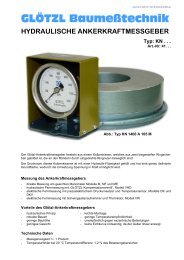
Version: 14.01.2003 / IG / RA / P075.07.01.00.00.001R01_engl.doc<br />
<strong>GLÖTZL</strong> Baumeßtechnik<br />
VERTICAL COMPASS PROBE<br />
Type: NMG D-K<br />
Art. No.: 75.07<br />
The vertical compass NMG D-K is used for torsion measurement in vertical guide<br />
tubes.<br />
Inductive Pick-Up<br />
The vertical compass probe is manufactured of rust- and acid-resistant material<br />
and is equipped with movable guiding reels for measurement of profile tubes.<br />
The main piece of this transducer is a magnetic field sensor which can precisely<br />
determine the alignment of an installed guide tube over its total length by the earth<br />
magnetic field.<br />
By this measurement, the axial distortion of the measuring tube can be determined.<br />
During evaluation, the distortion values are used for directional correction of the<br />
real inclination measuring values in two directions A/B.<br />
Furthermore, the compass is equipped with two inclination angle transducers which<br />
are displaced by a degree of 90° one to each other.<br />
They are only used for the orientation of the magnetic field sensor and thus cannot<br />
be considered for borehole measurement.<br />
Standard length of the probe is 0.5 m. By means of an elongation, the probe can<br />
be elongated to a measuring length of 1 m.<br />
Figure: Vertical compass probe and probe elongation<br />
Technical Data:<br />
Probe diameter:<br />
<strong>Measuring</strong> length:<br />
Weight:<br />
Total lengths:<br />
<strong>Measuring</strong> range: +/-30°<br />
Absolute accuracy +/-20°<br />
to mag. north:<br />
Relative accuracy: < +/-1°<br />
Hysteresis: < +/-0.5°<br />
32.0 mm<br />
0.5 m, 1 m elongation<br />
2.4/3.2 kgs<br />
700/1200 mm<br />
Operating range: -5 °C up to +60 °C<br />
Diameter of guide tube:<br />
max. 75, min. 35 mm<br />
Models:<br />
75.07.01 NMG D-K Compass probe<br />
75.02.00.01 NMV 0,5 Compass probe elongation for 1 m meas. length,<br />
dismountable<br />
<strong>GLÖTZL</strong> <strong>Gesellschaft</strong> <strong>für</strong> Baumeßtechnik <strong>mbH</strong> · Forlenweg 11 · 76287 Rheinstetten · Germany<br />
+49 (0)721 51 66 - 0 · +49 (0)721 51 66 - 30 · http://www.gloetzl.com · info@gloetzl.com<br />
© Glötzl <strong>Gesellschaft</strong> <strong>für</strong> Baumeßtechnik <strong>mbH</strong>
Version: 03.02.2006 / IG / RA / P086.00.00.00.00.001R02_engl<br />
<strong>GLÖTZL</strong> Baumeßtechnik<br />
DIPMETER Standard<br />
Dipmeter with Temperature Display<br />
Dipmeters are used for simple recording of a water level<br />
referred to a surface reference point. The measuring<br />
cable is graduated in black for centimeters and in red for<br />
meters. As soon as the dispmeter is submerged in<br />
water, the red signal diode is flashing and the buzzer in<br />
the cable reel is signalizing the water contact. By light<br />
lifting of probe, the signals are going out so that the<br />
switch actuation point which is equal to the water level<br />
can precisely be determined. Due to the very low power<br />
requirement by the automatic start und stop function of<br />
the instrument, the operating time will be one year or<br />
more according to the appli-cation frequency. Besides<br />
the standard version, also a model with integrated<br />
temperature indication is available. The temperature<br />
indication is done automatically after approx. 10<br />
seconds of water contact. For measurements outside of<br />
water, e.g. for air temperature measurement, the unit<br />
can be started by a push-button. After 30 seconds, the<br />
unit is automatically switched off.<br />
Cable Reel:<br />
Steel frame with plastic reel for measuring cable and<br />
integrated electronics.<br />
<strong>Measuring</strong> Cable:<br />
Plastic flat cable with two cable strands and three Kevlar<br />
cores for high-tensile strength; graduation in centimeters.<br />
Plumb:<br />
Manufactured of brass, chromium-plated, with electrode,<br />
strain relief and buckling protection for measuring tape,<br />
Ø16 mm.<br />
Current Supply:<br />
Commercially approved 9 V block batteries<br />
Delivery Volume:<br />
Complete operative units with measuring lengths of 15<br />
up to 200 m; specific measuring lengths on request.<br />
Model with Temperature Indication:<br />
3 ½ digit temperature indication LCD<br />
Temperature indication –5 °C up to +70 °C<br />
Resolution 0.1 °C<br />
<strong>Measuring</strong> accuracy ±0.3 °C<br />
Application Ranges:<br />
Measurements of water level and temperature in:<br />
Observation levels – Borings – Wells<br />
Caverns and galleries – Bodies of water – Containers<br />
Dipmeters, article numbers and cable lengths:<br />
Dipmeter standard model<br />
Dipmeter with integrated<br />
temperature indication<br />
Type: WL . . .<br />
Art. No.: 86. . . .<br />
P086.01FO01.jpg<br />
P086FO02.tif<br />
Cable lengths [m] Art. No.: 15 30 50 100 150 200<br />
Dipmeter standard 86.01 .01 .02 .03 .05 .06 .07<br />
Dipmeter with temperature display 86.01 .21 ,22 .23 .25 .26 .27
Version: 03.02.2006 / IG / RA / P086.00.00.00.00.001R03_engl.doc<br />
System of a standard water level<br />
Head-point type in filter<br />
Surface<br />
4<br />
4a<br />
9<br />
10<br />
Street prot. cap 10<br />
Screw cap<br />
Concr. plate<br />
4<br />
Meas. tube of PVC<br />
w. telesc. bushing<br />
NG 4 / 5 / 6,3 2<br />
Meas. tube of PVC<br />
w. screw bushing<br />
NG 4 / 5 / 6,3 1<br />
P086SB01.vsd<br />
Filling: Sand,<br />
gravel, insulating<br />
material etc.<br />
Sealing: Clay, clay<br />
balls,expand. clay,<br />
bentonite etc.<br />
Filter tips in different<br />
types filled with finegrained<br />
gravel<br />
4<br />
4a<br />
9<br />
10<br />
5 6<br />
7 8<br />
Meas. tube with end cap of PVC<br />
Head tube 2", closing cap with key 2 m long<br />
Protection tube heavy-type,<br />
closing cap with key 1.5 m long<br />
Street cap for subsurface installation for<br />
pavements/roadways DIN 4055<br />
P086SB02.vsd<br />
Assembly:<br />
On one side, the measuring tubes have an external thread and on the other side a screw bushing or<br />
telescopic bushing with internal thread. All parts can be screwed together wihout any tools. To avoid<br />
penetration of pollution, the protection caps must be attached.<br />
Article numbers for order of measuring tubes and accessories:<br />
Meas. tubes PVC, NG [outer Ø in cm] NG 4 NG 5 NG 6,3<br />
Ø 40x3 mm Ø 50x3.5 mm Ø 63x7 mm<br />
1 Meas, tube w. screw bushing each 2.5 m 89.01.01 89.10.01 89.20.01<br />
1a Screw/adhes. bushing f. shortening 89.01.13 89.10.13<br />
2 Meas. tube w. telescopic bushing each 2.5 m 89.01.02 89.10.02 89.20.03<br />
3 Closing cap of PVC for base 89.01.11 89.10.11 89.20.11<br />
4 Screw-/end cap of PVC for head point 89.01.12 89.10.12 89.20.12<br />
4a Head tube 2“, closing cap with key 2m long<br />
5 Ceramic filter in cylindrical form Ø 50x120 mm 89.60.01.01 89.60.01.01 89.60.01.01<br />
6 Ceramic filter in cylindrical form Ø 50x250 mm 89.60.01.03 89.60.01.03 89.60.01.03<br />
7 PVC tube with plastic filter Ø 25x250 mm 89.60.10.01 89.60.10.01 89.60.10.01<br />
8 Injection tube with plastic filter Ø 25x250 mm 89.60.20.01 89.60.20.01 89.60.20.01<br />
9 Protection tubes heavy-type 6“ , length 1.5 m with closing cap 89.40.01<br />
10 Street cap with subsurface head point DIN 4055 60.01.04.31<br />
Subject to technical alterations!<br />
<strong>GLÖTZL</strong> <strong>Gesellschaft</strong> <strong>für</strong> Baumeßtechnik <strong>mbH</strong> · Forlenweg 11 · 76287 Rheinstetten · Germany<br />
+49 (0)721 51 66 - 0 · +49 (0)721 51 66 - 30 · http://www.gloetzl.com · info@gloetzl.com<br />
© Glötzl <strong>Gesellschaft</strong> <strong>für</strong> Baumeßtechnik <strong>mbH</strong>
Version: 25.04.2005 / IG / RA / P075.10.13.00.00.001R02_engl.doc<br />
<strong>GLÖTZL</strong> Baumeßtechnik<br />
INCLINOMETER INTERFACE<br />
Type: NDI 11/12<br />
Art. No.: 75.10.12/13<br />
The NDI 11/12 is used for online – measurement of Glötzl digital inclinometer and Glötzl compass probe. The<br />
NDI 11/12 is performing two functions: On the one hand, the NDI 11/12 is delivering the energy supply of the<br />
inclinometer, and on the other hand the digital signal of the inclinometer is transferred to the standard RS232<br />
interface.<br />
Figure 1: NDI 12<br />
Connections NDI 11/12<br />
(1) Low batt display<br />
(2) Connection for cable reel<br />
(3) Connection for mains charger<br />
or car battery charging cable<br />
(4) Connection for data transfer (PC)<br />
NDI 11/12<br />
Cable reel<br />
Laptop with GLNP Software<br />
Digital inklinometer /<br />
compass probe<br />
Figure 2: Connections NDI 12<br />
Figure 3: <strong>Measuring</strong> arrangement for inclinometer measurement<br />
with the NDI 11/12
Version: 25.04.2005 / IG / RA /P075.10.13.00.00.001R02_engl.doc<br />
The unit NDI 11/12 has an integrated 12V lead accumulator with which operating times of > 50 hours can be<br />
achieved.<br />
If the capacity of the accumulator should not be sufficient, it is also possible to charge the NDI 11/12 from the<br />
car on-board supply (12V).<br />
On-board supply of car 12 V<br />
NDI 11/12<br />
Tripple connector of car<br />
Laptop with GLNP Software<br />
12V Converter<br />
for laptop<br />
Figure 4: Assembly of energy supply from on-board supply of car<br />
Technical Data:<br />
NDI 11<br />
- Accumulator: 12V/7.2Ah lead accu<br />
- Operating time: > 25 hours with<br />
standard NMG D<br />
- Charging time: < 15 hours with<br />
empty accu<br />
- Interface: RS232<br />
- Casing: Aluminium, IP 64,<br />
- Dimensions: 170 x 115 x 210 mm<br />
(L x W x H)<br />
- Weight: 4.9 kgs<br />
- Operating temperature: -10 °C up to +50 °C<br />
NDI 12<br />
- Accumulator: 12V/7.2Ah lead accu<br />
- Operating time: > 50 hours with<br />
standard NMG D<br />
- Charging time: < 40 hours with<br />
empty accu<br />
- Interface: RS232<br />
- Casing: Polyester, IP 54,<br />
splash-proof<br />
- Dimensions: 220 x 120 x 90 mm<br />
(L x W x H)<br />
- Weight: 4.0 kgs<br />
- Operating temperature: -10 °C up to +50 °C<br />
Delivery Volume / Accessories:<br />
- NDI 11 with integrated accu and charger<br />
- Battery charging cable for car<br />
- Serial cable SUB-D 9-core for connection to<br />
PC<br />
- Transfer cable for connection to PC<br />
Delivery Volume / Accessories:<br />
- NDI 12 with integrated accu<br />
- Mains charger 12V/600mA with charging<br />
control display<br />
- Battery charging cable for car<br />
- Serial cable SUB-D 9-core for connection to<br />
PC<br />
Optional Accessories:<br />
- Triple connector for car for simultaneous<br />
buffering of NDI 12 and laptop<br />
<strong>GLÖTZL</strong> <strong>Gesellschaft</strong> <strong>für</strong> Baumeßtechnik <strong>mbH</strong> · Forlenweg 11 · 76287 Rheinstetten · Germany<br />
+49 (0)721 51 66 - 0 · +49 (0)721 51 66 - 30 · http://www.gloetzl.com · info@gloetzl.com<br />
© Glötzl <strong>Gesellschaft</strong> <strong>für</strong> Baumeßtechnik <strong>mbH</strong>
Version: 09.10.2003 / IG / RA / P075.15.00.00.00.001R00_engl.doc<br />
<strong>GLÖTZL</strong> Baumeßtechnik<br />
CABLE REEL<br />
Light-weight model Type: NMK 2 / 3<br />
Art. No.: 75.15. . .<br />
Light-weight cable reel type NMK 2 / 3 with slip ring transmission 6pole for vertical and horizontal inclination<br />
measuring probes.<br />
The cable reel in light-weight execution has 6 slip ring contacts. The 6-core measuring cable with Kevlar core<br />
and PUR-covering; minimum tractive force 1500 N; weight 110g/m, is marked each 0.5 m and equipped with<br />
a plug connector for measuring probes.<br />
Technical data:<br />
Art. No.: Type Winding width<br />
(mm)<br />
Core ∅ (mm) Max. ∅ (mm) Weight (kg)<br />
75.15.01.01 NMK 2 150 170 380 6<br />
75.15.02.01 NMK 3 150 170 470 8,5<br />
Max. cable lengths for cable diameter 10 mm<br />
NMK 2 = 100 m cable<br />
NMK 3 = 200 m cable
Version: 09.10.2003 / IG / RA / P075.15.00.00.00.001R00_engl.doc<br />
CABLE REEL<br />
Heavy-weight model Type: MK 4 / 5 / 6<br />
Art. No.: 75.15. . .<br />
Special cable reels MK 4 / 5 and 6 for measuring cables with slip ring transmission 6pole, max. 8pole for<br />
vertical and horizontal inclination measuring probes.<br />
Crank drive with 1:2 reduction and mechanical brake. The 6-core measuring cable with Kevlar core and PURcovering;<br />
minimum tractive force 1500 N; weight 110g/m, is marked each 0.5 m and equipped with a plug<br />
connector for the measuring probes.<br />
On request, the cable reel is also available with motor.<br />
Technical data:<br />
Winding width:<br />
Winding diameter:<br />
MK 4 = 280 mm / MK 5 = 380 mm / MK 6 = 480 mm<br />
Core ∅ 170 mm, max. ∅ 450 mm<br />
Art. No.: Type Slip<br />
rings<br />
Winding width<br />
Weight<br />
without cable<br />
Dimensions<br />
L/D/H mm<br />
75.15.03.01 MK 4/6 6 280 17 kgs 540/500/500<br />
75.15.04.01 MK 5/6 6 380 18 kgs 640/500/500<br />
75.15.05.01 MK 6/6 6 480 19 kgs 740/500/500<br />
75.15.06.01 MK 4/8 8 280 17 kgs 540/500/500<br />
75.15.07.01 MK 5/8 8 380 18 kgs 640/500/500<br />
75.15.08.01 MK 6/8 8 480 19 kgs 740/500/500<br />
Cable length for cable diameter 10 mm:<br />
MK 4 max. 200 m<br />
MK 5 max. 350 m<br />
MK 6 max. 500 m<br />
Subject to technical alterations<br />
<strong>GLÖTZL</strong> <strong>Gesellschaft</strong> <strong>für</strong> Baumeßtechnik <strong>mbH</strong> · Forlenweg 11 · 76287 Rheinstetten · Germany<br />
+49 (0)721 51 66 - 0 · +49 (0)721 51 66 - 30 · http://www.gloetzl.com · info@gloetzl.com<br />
© Glötzl <strong>Gesellschaft</strong> <strong>für</strong> Baumeßtechnik <strong>mbH</strong>
Version: 16.06.2008 / JSG / IG / SP / P075.25.00.00.00.001R00_engl.doc<br />
<strong>GLÖTZL</strong> Baumeßtechnik<br />
Guide bars<br />
Aluminium channel type GUS Art. No.: 75.25.<br />
Application range:<br />
This bars enables an exact positioning of probes in horizontal<br />
and inclined borings.<br />
Models:<br />
• Quick coupling without guide little wheel, more suitable for<br />
short measuring lengths<br />
• Quick coupling with 3 nos. of guide little wheels for reduction<br />
of the friction, therefore also suitable for larger measuring<br />
lengths<br />
Specifications:<br />
• Material: Aluminium channel 15x15x2 mm<br />
• Length of each rods: Optional 1.5 m or 2.0 m<br />
• Weight: Approx. 0.6 kg (for 2.0m)<br />
Article numbers:<br />
• Connection piece probe-bars 75.25.01<br />
• Bars GUS 0/1.5; without little wheel, 1.5 m 75.25.12<br />
• Bars GUS 0/2 ; without little wheel, 2.0 m 75.25.13<br />
• Bars GUS 3/1,5; 3fold little wheel, 1.5 m 75.25.14<br />
• Bars GUS 3/2 ; 3fold little wheel, 2.0 m 75.25.15<br />
Glass fibre bars Art. No.: 75.26.<br />
Application range:<br />
The glass fibre bars is suitable for a flexible guidance of probes<br />
in horizontal and inclined borings with large direction<br />
changes. By its small weight, the glass fibre bars is especially<br />
applicable in impassable areas.<br />
Models:<br />
• Quick coupling without guide little wheel, more suitable for<br />
short measuring lengths<br />
• Quick coupling with 4 nos. of guide little wheels for reduction<br />
of the friction, therefore also suitable for larger measuring<br />
lengths<br />
Specifications:<br />
• Material: Glass fibre rod with protective jacket<br />
• Diameter: 30 mm (at coupling point)<br />
43 mm (at coupling with guide little wheel)<br />
Outer diameter of glass fibre: 11 mm<br />
• Length of each rods: Optional 1.5 m and 2.0 m<br />
or in one piece up to max. 300 m coiled up<br />
Article numbers:<br />
• Connection piece probe-bars 75.25.01<br />
• Bars GUS 4/2G; 4fold little wheel, 2.0 m 75.25.16<br />
• Reel with glass fibre rod 75.26.01
Version: 16.06.2008 / JSG / IG / / SP / P075.25.00.00.00.001R00_engl.doc<br />
Aluminium full section type<br />
GVS<br />
Art. No.: 75.30.<br />
Application range:<br />
The torsion rigid full section bars with patented coupling is<br />
mainly used in those cases where guidance und positioning of<br />
borehole probes have to be carried out with an utmost of accuracy.<br />
Models:<br />
• Quick coupling without guide little wheel, more suitable for<br />
short measuring lengths<br />
• Quick coupling with 2 nos. of guide little wheels for reduction<br />
of the friction, therefore also suitable for larger measuring<br />
lengths<br />
Specifications:<br />
• Material: Aluminium full section with cable notch<br />
• Diameter: 30 mm (GVS bars - standard);<br />
48 mm (at coupling with guide little wheel)<br />
• Length of each bars: 2.0 m<br />
• Weight: Approx. 1.4 kg (for 2.0 m)<br />
Article numbers:<br />
• Connection piece probe -bars 75.30.01<br />
• Bars GVS 2/2 ; 2fold little wheel, 2.0 m 75.30.11<br />
• Bars GVS 0/2 ; without little wheel, 2.0 m 75.30.12<br />
Stainless steel full section type<br />
GAVS<br />
Art. No.: 75.31.<br />
Application range:<br />
The torsion rigid VA full section bars with patented coupling is<br />
mainly used in those cases where guidance and positioning of<br />
borehole probes have to be carried out with an utmost high<br />
accuracy and in an aggressive surrounding.<br />
Models:<br />
• Quick coupling without guide little wheel, more suitable for<br />
short measuring lengths<br />
• Quick coupling with 2 nos. of guide little wheels for reduction<br />
of the friction, therefore also suitable for larger measuring<br />
lengths<br />
Specifications:<br />
• Material: Stainless steel full section with cable notch<br />
• Diameter: 30 mm (GAVS bars - standard);<br />
48 mm (at coupling with guide little wheel)<br />
• Length of each bars: 2.0 m<br />
• Weight: Approx. 2.6 kg (for 2.0 m)<br />
Article numbers:<br />
• Connection piece probe-bars 75.31.01<br />
• Bars GAVS 2/2; 2fold little wheel, 2.0 m 75.31.12<br />
Subject to technical alterations<br />
<strong>GLÖTZL</strong> <strong>Gesellschaft</strong> <strong>für</strong> Baumeßtechnik <strong>mbH</strong> · Forlenweg 11 · 76287 Rheinstetten · Germany<br />
+49 (0)721 51 66 - 0 · +49 (0)721 51 66 - 30 · http://www.gloetzl.com · info@gloetzl.com<br />
© Glötzl <strong>Gesellschaft</strong> <strong>für</strong> Baumeßtechnik <strong>mbH</strong>
Version: 21.10.2003 / IG / RA / P075.30.20.00.00.001R00_engl.doc<br />
<strong>GLÖTZL</strong> Baumeßtechnik<br />
RODS SLIDING EQUIPMENT for<br />
BOREHOLE PROBE-INCLINOMETER PROBE<br />
Type: GSE<br />
Art. No.: 75.30.20<br />
The rods sliding equipment is used for sliding and drawing of rods for guidance of probes. It is employed for<br />
situations in which the sliding in and drawing is only possible with big forces or even if it is not possible at all.<br />
Figure: Rods sliding equipment - Lengths of rods: 2 m<br />
- Advance control in steps up to 1 m<br />
Technical data (rods sliding equipment):<br />
Dimensions:<br />
Weight:<br />
3000 (L), 400 (W), 580 (H) [mm]<br />
approx. 130 kgs<br />
Figure: Hydraulic pump with control unit<br />
Technical data (hydraulic pump):<br />
Supply: 230 V, 50 Hz<br />
Output: 2.2 kW, 10.9 r/min<br />
Tank volume: 25 liters hydraulic oil<br />
Dimensions: 1000 (L), 340 (W), 830 (H) [mm]<br />
Weight: approx. 120 kgs<br />
Figure: Stationary clamping unit,<br />
supporting rods and<br />
connections for hydraulics<br />
Figure: Approach switch, bearing<br />
of hydraulic cylinder<br />
Figure: Movable thrust unit and<br />
fixing flange for borehole<br />
mouth<br />
<strong>GLÖTZL</strong> <strong>Gesellschaft</strong> <strong>für</strong> Baumeßtechnik <strong>mbH</strong> · Forlenweg 11 · 76287 Rheinstetten · Germany<br />
+49 (0)721 51 66 - 0 · +49 (0)721 51 66 - 30 · http://www.gloetzl.com · info@gloetzl.com<br />
© Glötzl <strong>Gesellschaft</strong> <strong>für</strong> Baumeßtechnik <strong>mbH</strong>
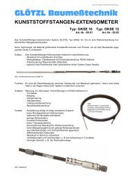
Version: 10.02.2009 / IG / SP / P077.00.00.00.00.001R08_engl.doc<br />
<strong>GLÖTZL</strong> Baumeßtechnik<br />
BORE HOLE LENGTH MEASURING PROBE<br />
• Easily to handle and use<br />
• Only one operating person required<br />
- also for transport to measuring site<br />
• Quick measuring sequence<br />
• Economical measuring system<br />
• Combined length measurement possible<br />
with inclination measurements<br />
vertical and horizontal<br />
• No guide rods<br />
• Accessories of Glötzl standard inclination<br />
measuring probe can be used.<br />
• Digital data transfer<br />
The bore hole length measuring probe is<br />
a measuring device which takes account of<br />
the requirements of a site-adjusted<br />
application.<br />
The new development has the advantage –<br />
compared with the conventional probes -<br />
that the measuring expenditure is<br />
minimized as far as possible. By this, the<br />
measurement can be carried out without<br />
rods – similar to an inclination<br />
measurement -, but in the vertical area.<br />
The measuring tubes are installed in single<br />
lengths of 1 m and have measuring<br />
connections of metal or plastic material for<br />
orientation of the length measuring probe,<br />
dependent on the required measuring<br />
accuracy. For installation, the measuring<br />
tubes are connected with each other in<br />
such a way that they can record settlements<br />
and deformations in the construction by the<br />
case friction and thus make them<br />
measurable for the probe.<br />
The essential novelty of the measuring<br />
probe is based on the arrangement of guide<br />
rods with a balancer system, which enables<br />
the step-by-step measurement of the single<br />
guide couplings at the measuring<br />
connections by fine-tuned elastic forces.<br />
The balancer at the bottom of the probe is<br />
kept by the measuring mark. The upper<br />
balancer is drawn up till the upper<br />
measuring connection by overdraw of the<br />
elastic force at the lower balancer part<br />
which is connected with the displacement<br />
transducer for length measurement. The<br />
appearing measured value is accepted as<br />
length dimension. For placing the probe at<br />
next tube coupling, with a distance of<br />
Type: BES– E32/1<br />
E32/1A+B<br />
E32/1H<br />
E32/1A+B+H<br />
Art. No.: 077…<br />
approx. 1 m, the probe is slightly dropped<br />
and drawn over the measured measuring<br />
mark with slow speed. At the same time,<br />
the incli-nation measuring values are also<br />
recorded at pick-up of meas. values,<br />
dependent on probe model. Recording of<br />
inclinations measurements in connection<br />
with the length measurement enables the<br />
determination of exact deformation lines of<br />
an instrumented measuring distance for<br />
each meter of measuring length.<br />
<strong>Measuring</strong> probes:<br />
4 probe models are availabe for the<br />
different measuring tasks. The probe<br />
assemblage is constructed in such a way<br />
that it is possible to upgrade the basic<br />
equipment for length measurement with<br />
additional sensors for vertical inclination<br />
measurement, and, if required, also for<br />
horizontal measurement. An installed<br />
controller is digitalizing the measured<br />
values and is transferring them for data<br />
recording via a RS 485 interface.<br />
Measurement:<br />
Basically, this is exactly done like a vertical<br />
or horizontal inclination measurement with<br />
the same measuring equipment. Readout<br />
units VMG 14 and evaluation software<br />
GLNP are already equipped for length<br />
measurement.<br />
If the Glötzl inclination measuring<br />
equipment with corresponding readout unit<br />
and software are already existing, only the<br />
supply of the bore hole length measuring<br />
probe is required for the solution of the<br />
measuring tasks.<br />
Figure: Bore hole length measuring probe, basis 1 m
Version: 10.02.2009 / IG / SP / P077.00.00.00.00.001R08_engl.doc<br />
Vertical length- and inclination measurements:<br />
The measurement is done like a vertical inclination<br />
measurement. Additionally, a scanning of the<br />
measuring marks has to be done with the probe and<br />
their distance to each other be measured. In case of<br />
an equipment of probe with inclination sensors,<br />
type E32/1 A+B, the inclination angles are also<br />
recorded with the length measurement.<br />
Probes:<br />
Type E32/1<br />
Type E32/1 A+B<br />
Type E32/1 H<br />
Type E32/1 A+B+H<br />
Horizontal length- /inclination measurements:<br />
The procedure is the same as a horizontal<br />
inclination measurement with rods. By recording of<br />
measuring mark distances, it is similar to the<br />
measurement of horizontal settlement plates,<br />
however with high accuracy – also known as<br />
expanding level measurement. With the probe type<br />
E32/1 H, also the vertical settlements are recorded<br />
by the inclination angles.<br />
Model only as length measuring probe<br />
Length measuring probe with vertical inclination sensors A and B (X/Y)<br />
Length measuring probe with sensor for horizontal inclination measurement H<br />
Length measuring probe with vertically and horizontally measuring inclination sensors<br />
<strong>Measuring</strong> tubes:<br />
ABS 50, Ø 49/55 mm with plastic measuring marks (2“-tubes), type ABS BES-RK 50<br />
ALU 50, Ø 49/53 mm with metal measuring marks (2“-tubes), type ALU BES-RA 50<br />
PVC 60, Ø 60/70 mm with metal- or plastic measuring marks (2,75“-tubes), type PVC BES-RM 60<br />
Figure: Probe in measuring tube<br />
Figure: Meas. tubes and accessories<br />
Sequence meas. tube for further 1<br />
m<br />
measuring length<br />
Settlement bushing<br />
Probe head at top with plug<br />
connection and 2 reel guides<br />
Electronics with temperature<br />
sensor Data transfer by RS 485<br />
Meas. tube for 1 m meas. length<br />
Sensor for vertical incl.<br />
measurement Axes A,B (X/Y)<br />
Sensor for horizontal<br />
measurement H<br />
max. 30 mm<br />
max. 30 mm<br />
Settlement bushing<br />
Meas. tube bottom<br />
End cap<br />
Displ. transducer<br />
for ± 25 mm<br />
meas. basis<br />
975 to 1025 mm<br />
Probe head at bottom with<br />
2 reel guides<br />
Motion distance for length<br />
measurement<br />
position at 1000 mm<br />
Technical data general:<br />
Probe length, basic length 1000 mm<br />
<strong>Measuring</strong> length 975 up to 1025 mm<br />
Probe diameter<br />
32/40 mm<br />
Data transfer digital RS 485<br />
Probe temperature ± 0.1 °C<br />
Temperature range -5 up to +60 °C<br />
Material<br />
Stainless steel<br />
Length measurement E:<br />
Probe accuracy ± 0.02 mm<br />
<strong>Measuring</strong> range<br />
50 mm<br />
Meas. value resolut. max. 0.001mm<br />
Standard<br />
0.01 mm<br />
Operation accuracy:<br />
Vertical*)<br />
Metal meas. marks ± 0.05 mm<br />
Plastic meas. marks ± 0.1 mm<br />
Horizontal*)<br />
Metal meas. marks ± 0.1 mm<br />
Plastic meas. marks ± 0.1 mm<br />
Inclination measurement A+B<br />
vertical with 2 measuring axes:<br />
<strong>Measuring</strong> range<br />
Maximum 90°, normal ± 30°<br />
Measured value resolution<br />
Maximum up to 5,7° sine 0.00001<br />
Standard sine 0.0001<br />
Accuracy<br />
± 0.1 mm/m<br />
Inclination measurement H<br />
horizontal with 1 measuring axis:<br />
<strong>Measuring</strong> range<br />
Maximum 90°, normal ± 30°<br />
Measured value resolution<br />
Maximum up to 5,7° sine 0.00001<br />
Standard sine 0.0001<br />
Accuracy<br />
± 0.1 mm/m<br />
*) depending on the conditions<br />
caused by installation and<br />
measurements<br />
Configuration with max. resolution only as option available<br />
<strong>GLÖTZL</strong> <strong>Gesellschaft</strong> <strong>für</strong> Baumeßtechnik <strong>mbH</strong> · Forlenweg 11 · 76287 Rheinstetten · Germany<br />
+49 (0)721 51 66 - 0 · +49 (0)721 51 66 - 30 · http://www.gloetzl.com · info@gloetzl.com<br />
© Glötzl <strong>Gesellschaft</strong> <strong>für</strong> Baumeßtechnik <strong>mbH</strong><br />
Subject to technical alterations
-40 / +10 mm<br />
-25 / +25 mm<br />
-10 / +40 mm<br />
- = Asiento<br />
+ = Elevación<br />
del rango<br />
disponible<br />
<strong>Gesellschaft</strong> <strong>für</strong> Baumeßtechnik <strong>mbH</strong><br />
76287 Rhe instetten • Forlenweg 11 • Germa ny<br />
-40 / +10 mm<br />
-25 / +25 mm<br />
-10 / +40 mm<br />
- = Asiento<br />
+ = Elevación<br />
del rango<br />
disponible<br />
<strong>Gesellschaft</strong> <strong>für</strong> Baumeßtechnik <strong>mbH</strong><br />
76287 Rhe instetten • Forlenweg 11 • Germa ny<br />
-40 / +10 mm<br />
-25 / +25 mm<br />
-10 / +40 mm<br />
- = Asiento<br />
+ = Elevación<br />
del rango<br />
disponible<br />
<strong>Gesellschaft</strong> <strong>für</strong> Baumeßtechnik <strong>mbH</strong><br />
76287 Rhe instetten • Forlenweg 11 • Germa ny<br />
Version: 30.01.2008 / IG / RA / P077.00.00.00.00.003R02_engl.doc<br />
<strong>GLÖTZL</strong> Baumeßtechnik<br />
MEASURING TUBES for BOREHOLE<br />
LENGTH MEASURING PROBE<br />
Type ALU BES-RA 50 Art. No.: 77.09<br />
Technical data:<br />
• Aluminium measuring tube for borehole length measuring<br />
probe in lengths of 1 m each<br />
• No pressurized watertight model of aluminium<br />
• Nominal diameter 50 mm<br />
• Stable execution, wall thickness 2 mm<br />
Meas. tube: Alu Ø 49/53 mm with 4 grooves, length 1 m<br />
Couplings: Alu Ø 54/58 mm with 4 grooves, telescopic<br />
model for total 50 mm meas. length, no<br />
pressurized watertight model<br />
Spec. weight: Tube incl. interior space 0.7 kg/m<br />
Head point<br />
Meas. tube cover at the<br />
top with end cap<br />
type BES-KA 50<br />
Connecting box<br />
Specifications:<br />
• Material: Aluminium anodized<br />
• Length each [m]: 1,00<br />
Type<br />
A<br />
[mm]<br />
B<br />
[mm]<br />
C<br />
[mm]<br />
D<br />
[mm]<br />
2“ 49 53 54 58<br />
Glötzl<br />
Glötzl<br />
50 mm<br />
(+10 mm Elevation<br />
- 40 mm Settlement)<br />
<strong>Measuring</strong> tube<br />
type BES-RA 50<br />
Connecting box<br />
50 mm<br />
(+/- 25 mm)<br />
<strong>Measuring</strong> tube<br />
type BES-RA 50<br />
Connecting box<br />
50 mm<br />
(+10 mm Elevation<br />
- 40 mm Settlement)<br />
Article numbers:<br />
• Meas. tube, type ALU BES-RA 50, basic length 1 m<br />
incl assembly accessories 77.09.01<br />
• Head point, type BES-KA 50 77.09.01.11<br />
• Base, type BES-FA 50 77.09.01.10<br />
Assembly types:<br />
Tubes/couplings prefitted by factory. Before starting<br />
the assembly, it is determined, in which position the<br />
tubes have to be riveted together.<br />
Three prepared positions are available, provided<br />
with markings:<br />
Standard: +/-25 mm elevation and settlement<br />
Settlement: +10 mm elevation and -40 mm settlement<br />
Elevation: +40 mm elevation and -10 mm settlement<br />
Hereto also see figure on the right.<br />
Glötzl<br />
Base<br />
Meas. tube cover at the<br />
bottom with terminal plug<br />
type BES-FA 50<br />
The left figure shows the assembly positions.
Version: 30.01.2008 / IG / RA / P077.00.00.00.00.003R02_engl.doc<br />
Type PVC BES-RM 60 Art. No.: 77.12<br />
Technical data:<br />
• PVC measuring tube for borehole length measuring<br />
probe in lengths of 1 m each<br />
• Pressurized watertight model of PVC<br />
• Nominal diameter 60 mm<br />
• By plane surface, an execution in seals is simply<br />
possible.<br />
• Stable execution, wall thickness 5 mm<br />
Head Point<br />
<strong>Measuring</strong> tube cover at<br />
top with end cap<br />
type BES-KM 60<br />
Meas. tubes: PVC Ø 60/70 mm with 4 grooves<br />
Couplings: PVC Ø 70/90 mm with 4 grooves, telescopic<br />
execution for total 50 mm meas.<br />
length, , O-ring seal<br />
Weight: Tube incl. coupling 2.2 kgs<br />
Specifications:<br />
• Material: PVC; length each tube: 1.05 m incl. coupling<br />
• Outer diameter of coupling: 90 mm<br />
• Length of coupling: 200 mm, material: PVC grey<br />
• Length of each tube: 950 mm<br />
Pressurized-watertight<br />
Connection box<br />
Type<br />
A<br />
[mm]<br />
B<br />
[mm]<br />
C<br />
[mm]<br />
2.75“ 60 70 65<br />
C<br />
A<br />
B<br />
<strong>Measuring</strong> tube<br />
type BES-RM 60<br />
Pressurized-watertight<br />
Connection box<br />
Article numbers:<br />
• Meas. tube, type PVC BES-RM 60, basic length 1 m<br />
incl. assembly accessories 77.12.01<br />
• Head point, type BES-KM 60 77.12.01.11<br />
• Base, type BES-FM 60 w. telescopic coupling 77.12.01.10<br />
Assembly types:<br />
Tubes/couplings are prefitted in factory. Before starting the assembly,<br />
it must be determined, in which position the tubes<br />
should be riveted to each other.<br />
Three prepared positions are available, provided with markings<br />
(prefitted in the factory acc. to indications of client):<br />
<strong>Measuring</strong> tube<br />
type BES-RM 60<br />
Standard: +/-25 mm elevation and settlement<br />
Settlement: +10 mm elevation and -40 mm settlement<br />
Elevation: +40 mm elevation and -10 mm settlement<br />
.<br />
Pressurized-watertight<br />
Connection box<br />
Base<br />
Meas. tube cover at bottom<br />
with terminal plug<br />
type BES-FM 60
Version: 30.01.2008 / IG / RA / P077.00.00.00.00.003R02_engl.doc<br />
Type PVC BES-RM 60 Art. No.: 77.12<br />
Arrangement and assembly of tube connection<br />
Marking for<br />
assembly at tube<br />
a)<br />
<strong>Measuring</strong> connection<br />
Marking at coupling<br />
d)<br />
Glued-in pins for<br />
groove guidance<br />
2 rivets for positioning<br />
b)<br />
Marking of assembly<br />
direction<br />
b)<br />
a) For assembly, the marking points must stand<br />
opposite to each other.<br />
b) Preassembly of the required measuring position<br />
by factory, with 2 grooves 3x14 mm, seal by silicone<br />
and adhesive tape<br />
c) Before installation of the measuring tube, the<br />
coupling side (with 0-ring) and the tube end must<br />
be sprayed with teflon spray for a better sliding<br />
into the 0-ring.<br />
d) Quick and easy fixing of the follow-up tube with<br />
coupling by a protective rod.<br />
Position +10 mm, -40 mm<br />
Position +/- 25 mm<br />
Position +40 mm, -10 mm<br />
Following-up<br />
measuring<br />
tube<br />
Rivets 3 x 14 mm<br />
After self-assembly,<br />
please check tubes<br />
for operability<br />
<strong>Measuring</strong><br />
tube coupling<br />
Assembly<br />
plate<br />
Borehole<br />
piping
-40 / +10 mm<br />
-25 / +25 mm<br />
-10 / +40 mm<br />
- = Settlement<br />
+ = Elevation<br />
of the available<br />
measuring range<br />
Gesell schaft <strong>für</strong> Bau meßtechnik <strong>mbH</strong><br />
76287 Rheinstetten • Forlenweg 11 • Germany<br />
-40 / +10 mm<br />
-25 / +25 mm<br />
-10 / +40 mm<br />
- = Settlement<br />
+ = Elevation<br />
of the available<br />
measuring range<br />
Gesell schaft <strong>für</strong> Bau meßtechnik mb H<br />
76287 Rheinstetten • Forlenweg 11 • Germany<br />
Version: 30.01.2008 / IG / RA / P077.00.00.00.00.003R02_engl.doc<br />
Type ABS BES-RK 50 Art. No.: 77.11<br />
Application ranges:<br />
• For long-term measuring tasks<br />
• Standard instrumentation for up to approx. 50 m boring<br />
• On account of its lower self-stability, more suitable for<br />
recording of smaller local deformations.<br />
• Restriction: Smaller self-rigidity<br />
1,0 m 0,5 m<br />
Glötzl<br />
End cap KV51<br />
End tube with<br />
coupling<br />
BES-KK 50<br />
-40 / +10 mm<br />
-25 / +25 mm<br />
-10 / +40 mm<br />
- = Settlement<br />
+ = Elevation<br />
of the available<br />
measuring range<br />
Glötzl<br />
<strong>Gesellschaft</strong> <strong>für</strong> Baumeßtech ni k <strong>mbH</strong><br />
76287 Rh einstetten • Forlenweg 11 • Ge rmany<br />
Assembly position for<br />
adjustment ±25 mm<br />
Specifications:<br />
• Material: ABS<br />
• Length each tube [m]: 1,00<br />
• Outer diameter of coupling [mm]: 67<br />
Type<br />
A<br />
[mm]<br />
B<br />
[mm]<br />
C<br />
[mm]<br />
D<br />
[mm]<br />
2“ 47 55 54 60<br />
Article numbers:<br />
• <strong>Measuring</strong> tube, type ABS BES-RK 50, basic length 1 m<br />
incl. assembly accessories 77.11.01<br />
• Head point, type BES-KK 50 77.11.01.11<br />
• Base, type BES-FK 50 77.11.01.10<br />
Assembly types:<br />
Tubes/couplings are prefitted in factory. Before starting the assembly,<br />
it must be determined, in which position the tubes should<br />
be riveted to each other.<br />
Three prepared positions are available, provided with markings:<br />
C<br />
A<br />
90°<br />
B<br />
D<br />
Standard:<br />
+/-25 mm elevation and settlement<br />
<strong>Measuring</strong> tube<br />
with coupling<br />
length 1 m with<br />
plastic measuring<br />
mark for probe<br />
position BES-RK 50<br />
Settlement: +10 mm elevation and -40 mm settlement<br />
Elevation: +40 mm elevation and -10 mm settlement<br />
0,5 m<br />
Glötzl<br />
End tube at base<br />
BES-FK 50<br />
End cap PV48<br />
<strong>GLÖTZL</strong> <strong>Gesellschaft</strong> <strong>für</strong> Baumeßtechnik <strong>mbH</strong> · Forlenweg 11 · 76287 Rheinstetten · Germany<br />
+49 (0)721 51 66 - 0 · +49 (0)721 51 66 - 30 · http://www.gloetzl.com · info@gloetzl.com<br />
© Glötzl <strong>Gesellschaft</strong> <strong>für</strong> Baumeßtechnik <strong>mbH</strong><br />
Subject to technical alterations
Version: 19.01.2005 / IG / SP / P078.00.00.00.00.001R02_engl.doc<br />
<strong>GLÖTZL</strong> Baumeßtechnik<br />
BOREHOLE MODULAR PROBE<br />
Type: BMS . . .<br />
Art. No.: 78. . .<br />
The borehole modular probe BMS... has been constructed for<br />
high-precision borehole surveying in two axes in horizontal and<br />
vertical tubes or borings.<br />
The modular construction offers the advantage that the basic<br />
probe can be adapted to the measuring tubes or borings by<br />
means of exchangeable guiding modules and can fulfil the<br />
demands of customary measurements by complementary<br />
probe modules.<br />
Guiding Modules<br />
♦ Wheel-balancers guidance for horizontal and vertical<br />
measuring tubes with guiding grooves<br />
♦ 3-point-balancers-roller guidance for precise measurements<br />
in borings or tubes with guide rods<br />
♦ 3-point-skid guidance with sliding reels for simple borehole<br />
surveying with guide rods<br />
♦ Solutions according to client’s specification<br />
Basic Probe and Extension Modules<br />
♦ Basic probe BMS-B35/1 with the measuring axes<br />
horizontal-H, vertical- A, vertical-B and temperature sensor<br />
♦ Precursor module –V35/1 with the measuring axes X and<br />
Y in reference to the basic probe<br />
♦ Video module –V40/1 with colour picture super VHS and<br />
wide-angle optics<br />
♦ Distortion angle module –D35/1 for torsion measurement<br />
of inclinometer guide tubes<br />
♦ Calibre module –K40/1 for recording of boring and measuring<br />
tube diameters<br />
♦ Compass probe –R40/1 for site measurement of horizontal<br />
borings without piping<br />
♦ Temperature module –T35/1 for determination of surface<br />
temperature in borings<br />
♦ Solutions according to client’s specification<br />
With the basic probe the user has a standard measuring unit<br />
for horizontal and vertical inclination measurements.<br />
Figure: Picture on the left - basic probe with precursor module with three-point reel guidance<br />
Picture on the right - guiding parts for grooved tube measurement
Version: 19.01.2005 / IG / SP / P078.00.00.00.00.001R02_engl.doc<br />
Basic Probe BMS-B35/1<br />
As basic version, the probe consists<br />
of a two-fold mounted probe part with<br />
exchangeable guiding modules and<br />
max. three inclinometer sensors for<br />
determination of two vertical and one<br />
horizontal inclination angle. For<br />
determination of the surrounding<br />
temperature a forth sensor is<br />
installed in the probe as temperature<br />
cell. The measured values are<br />
managed by a master controller with<br />
calibration constants and transferred<br />
by a RS485-interface.<br />
Basis probe, type BMS-35/1, as horizontal and vertical inclinometer<br />
For horizontal measurements (vertical deviation) the revolution of the probe<br />
by its longitudinal axis is without influence on the measured values<br />
For special Measurements, the distortion is determinable by the sensors<br />
for vertical measurements X+Y<br />
- Horizontal ±30° (90°), 1 measuring axis (vertical devitation)<br />
- Vertical ±30° (90°), 2 measuring axes<br />
V078SB01.vsd<br />
cable connection<br />
cable connection<br />
Borehole probe - basic module as horizontal and vertical inclinometer<br />
probe for measurement in grooved tube<br />
Reel-balancers-guidance for horizontal and vertical measuring tubes<br />
for grooved tubes of Ø 40 - 80 mm<br />
1000 mm<br />
Basic part w. connections for several guiding modules, basic length 1 m<br />
3-point-balancer-reel-guidance for suveying of boring and measuring<br />
tubes, guide modules for Ø 55 - 120 mm, exchangeable<br />
Conn. A1<br />
Conn. A2<br />
3-point-skid-guidance with sliding reels for borehole measurement with<br />
guiding rods, guide modules for Ø 55 - 120 mm, exchangeable<br />
Adapterconnector<br />
Electric cable<br />
connection<br />
Vertical A Horizontal H Vertical B<br />
- Inclinometer -<br />
Controller for analog/<br />
digital conversion<br />
Basic Probe BMS-B53/1<br />
and<br />
Precursor Module V35/1<br />
Basis probe<br />
Precursor<br />
Vertical probe<br />
For acquisition of the X-coordinates in the<br />
horizontal surveying, the precursor<br />
module is used by coupling to the basic<br />
probe. The module has an optical sensor<br />
for the measuring axes X and Y. The<br />
measured value is produced by the angle<br />
change of the precursor module to the<br />
basic module. These modules are<br />
mechanically connect-ed to each other by<br />
a ball and socket joint.<br />
Horizontal measuring probe<br />
Basis probe equipped with 3 inclination sensors for absolutely angel<br />
pic-up<br />
- Horizontal ±30° (90°), 1 measuring axis<br />
- Vertical X + Y Achse ±30° (90°), 2 measuring axes<br />
- Optical sensor for precursor X + Y ±1,5°, 2 measuring<br />
axis<br />
The computation of the horizontal deviation is done by specified<br />
dertermination of the starting direction. the vertical measurement is<br />
absolutelydone by inclination sensors.<br />
The measured values are managed by a slave-controller with calibration constants and transmitted via the<br />
existing RS485-interface.<br />
1,5° 1,5°
Version: 19.01.2005 / IG / SP / P078.00.00.00.00.001R02_engl.doc<br />
Video Module –V40/1<br />
The video probe is used as<br />
supplementation to the basic unit<br />
for borehole examination in connection with<br />
an inclination measurement.<br />
The video probe with accessories can also<br />
be used as single instrument with PC or<br />
television set. The record is done in colour<br />
with a CCD-color-camera in super VHS<br />
quality. Objective f = 3.5 mm<br />
Figure:<br />
Video recorder, cable reel, video probe and<br />
guide rods<br />
Video module -V40/1<br />
Model with skids<br />
500 - 1000<br />
Alternative model with reels for grooved tube<br />
500 - 1000<br />
Video<br />
Application fields<br />
Model with skids for an application in unpiped boring, with<br />
exchangeable sliding skids according to borehole diameter<br />
Compass Probe –R40/1<br />
for acquisition of the spatial location of an unpiped<br />
boring. Measurement is done by the ball-spherical<br />
capture of the earth magnetic field in 360° position.<br />
The analog measured values are digitally<br />
converted in the probe and transmitted with a<br />
networked communication computer in the form of<br />
a micro-controller 87C751 and a RS485-interface.<br />
The accuracy – compensated with the spatial<br />
position - is ±0.5° angle.<br />
The compass probe can be used as module in<br />
connection with the basic probe. For an<br />
independent measurement, the connection<br />
adapters and the guide shoes of the basic unit are<br />
required.<br />
Model with reels for inspection of grooved tubes<br />
V078SB05_engl.vsd<br />
Basis probe<br />
Compass<br />
Inclination<br />
±30°<br />
1000 200<br />
Alternative Construction<br />
Basis probe<br />
Compass<br />
Com<br />
.<br />
360°<br />
1500<br />
V0778SB07_engl.vsd
Version: 19.01.2005 / IG / SP / P078.00.00.00.00.001R02_engl.doc<br />
Acquisition of Measured Values Figure: Storage unit, type VMG 14.1<br />
The record of the measured values is done by a notebook with power<br />
supply unit or by a standard PC. The comfortable software already<br />
enables an evaluation resp. an analysis of the complex data during<br />
measurement on site. During the stepwise passage of the measuring<br />
distance the measuring sizes of the probe are directly processed in<br />
graphic form by the program and then displayed. For a sole data<br />
recording, a menu-guided storage unit is available.<br />
Evaluation examples with PC<br />
Shear rods with cable guidance, quick coupling and sliding reels in 2 m lengths<br />
Cable reels with slip-ring contacts<br />
Manual reel up to 100 m, type NMK2<br />
Manual-motor reel with cross shaft and cable counter up to<br />
up to 200 m, type NMK3 200 m, type MK 4/6, and up to 500 m, type MK 6/6<br />
<strong>GLÖTZL</strong> <strong>Gesellschaft</strong> <strong>für</strong> Baumeßtechnik <strong>mbH</strong> · Forlenweg 11 · 76287 Rheinstetten · Germany<br />
+49 (0)721 51 66 - 0 · +49 (0)721 51 66 - 30 · http://www.gloetzl.com · info@gloetzl.com<br />
© Glötzl <strong>Gesellschaft</strong> <strong>für</strong> Baumeßtechnik <strong>mbH</strong>
Version: 09.10.2003 / IG / RA / P078.01.04.02.00.001R00_engl.doc<br />
<strong>GLÖTZL</strong> Baumeßtechnik<br />
Borehole Modular Probe – Calibre<br />
Modulus<br />
Connection for guide part<br />
Type: BMS-FZ.. or BMS-FT..<br />
Type: BMS-VK45/4<br />
Art. No.: 78.01.04.02<br />
- Large standard meas. ranges from 80 mm up to 150 mm<br />
- Simultaneous measurement at 4 points at borehole wall<br />
- High accuracy<br />
- Simultaneous measurement of inclination- and calibre<br />
values, video inspection resp. compass measurement<br />
Application:<br />
The borehole calibre probe is used for recording of the borehole<br />
calibre in horizontal and vertical borings.<br />
The housing of the calibre probe is made of stainless steel and<br />
aluminium. By application of up-to-date materials, a total weight of<br />
less than 3 kgs can be achieved.<br />
By the three-point roller guidance with forced centering, the<br />
complete measuring unit is always guided in the centre of the<br />
boring.<br />
Function:<br />
The calibre probe has four measuring arms, displaced by 90° to<br />
each other.<br />
The measuring arms are separately movable and continuously<br />
scanning the borehole wall partition during a measurement. The<br />
movements of the measuring arms are recorded by 4 separate<br />
lineary displacement transducers and directly digitalized in the<br />
calibre probe. While doing this, the calibration coefficients -<br />
necessary for computation - are stored in a permanent memory in<br />
the calibre probe. By the internal front-end computer (microcontroller<br />
AT 90S8515), the data are transferred by the RS485-<br />
measuring bus, if required.<br />
The measuring arms of the calibre probe can be limited multistage<br />
at a maximum borehole diameter. By this, a hacking into cavities in<br />
the borehole wall can be avoided.<br />
<strong>Measuring</strong> procedure:<br />
The calibre probe is mounted as precursor before the Glötzl basic<br />
probe.<br />
Additionally, the measuring equipment can be provided with a<br />
compass module or a video module. By this, it is possible to carry<br />
out simultaneously in one measuring procedure a position<br />
measurement of the boring, the determination of the borehole<br />
calibre and also a video inspection.<br />
Connection for guide part<br />
Type: BMS-FZ..
Version: 09.10.2003 / IG / RA / P078.01.04.02.00.001R00_engl.doc<br />
Possible configurations of meas. modules with calibre probe:<br />
Meas.cable<br />
Meas.cable<br />
guide part<br />
Basic probe<br />
Baisc probe<br />
Führungsteil<br />
Calibre probe<br />
Calibre probe<br />
Guide part<br />
Compass Kompass<br />
The following figures are<br />
showing possible combinations<br />
of the single probe<br />
modules.<br />
uide part<br />
Führungsteil<br />
Guide part<br />
Meas.cable<br />
Basic probe<br />
Calibre probe<br />
Video Vido camera<br />
Guide part<br />
Führungsteil<br />
Guide part<br />
Meas.cable<br />
Basic probe<br />
Calibre probe<br />
Video camera<br />
Guide part<br />
Guide part<br />
Guide part<br />
Lateral view<br />
adapter<br />
Basic probe Calibre probe Video probe Lat. view<br />
adapter<br />
Compass<br />
Transport case consisting of:<br />
- Calibre probe<br />
- Calibration adapter<br />
- Video probe<br />
- Lateral view adapter<br />
Calibration adapter for calibre<br />
probe<br />
Art. No.: 78.01.04.03<br />
Technical data calibre probe:<br />
The accuracy of measuring arms can be<br />
tested with the calibration adapter and<br />
eventually be corrected.<br />
Outer diameter : Ø 45 mm<br />
Further diameters are available on<br />
Overall length : 880 mm<br />
request.<br />
Length to centre of the<br />
guide elements : 1000 mm<br />
Weight : 2.8 kgs<br />
Meas. range (calibre) : Standard: Ø 80 mm up to Ø 150 mm<br />
Further measuring ranges on request<br />
Linearity : < +/-0.4 mm,<br />
< +/-0.2 mm (typical)<br />
<strong>GLÖTZL</strong> <strong>Gesellschaft</strong> <strong>für</strong> Baumeßtechnik <strong>mbH</strong> · Forlenweg 11 · 76287 Rheinstetten · Germany<br />
+49 (0)721 51 66 - 0 · +49 (0)721 51 66 - 30 · http://www.gloetzl.com · info@gloetzl.com<br />
© Glötzl <strong>Gesellschaft</strong> <strong>für</strong> Baumeßtechnik <strong>mbH</strong>
Version: 09.10.2003 / IG / RA / P078.01.05.02.00.001R00_engl.doc<br />
<strong>GLÖTZL</strong> Baumeßtechnik<br />
BOREHOLE MODULAR PROBE-LATERAL<br />
VIEW ADAPTER<br />
Type: BMS-VS56/1<br />
Art. No.: 78.01.05.02<br />
• Simple assembly on Glötzl BMS-video module<br />
• Stepless adjustment of view direction, controllable by software (left, right, stop)<br />
• Stepless adjustment of size of picture cut-off by changing of distance between objective<br />
and mirror<br />
• Display of view direction in the picture<br />
• Manufactured of impact-resistant plastic<br />
The picture shown at the left<br />
is presenting the Glötzl<br />
lateral view adapter.<br />
1 2<br />
3<br />
1 = Lateral view adapter<br />
head, with motor<br />
2 = Reversing mirror<br />
3 = Guide shoe for attachment<br />
at video probe<br />
Application:<br />
The lateral view adapter is mounted as accessories at the Glötzl vido modulus. The view direction of the<br />
objective is laterally oriented by 90° by a mirror. By this it is possible to assess e.g. cavities in salt in a<br />
boring without distortion.<br />
The mirror can be controlled multistage by the control- and evaluation software GLNP (left, right, stop).<br />
Therefore, a complete view of the borehole dimension (360°) is possible.<br />
Photo in salt rock without lateral view adapter<br />
Photo in salt rock with lateral view adapter<br />
The proportion of dimensions can now correctly<br />
be interpreted.
Version: 09.10.2003 / IG / RA / P078.01.05.02.00.001R00_engl.doc<br />
Possible operating variants:<br />
The following figures are showing possible combinations of the Glötzl BMS-modules, for which the lateral view<br />
adapter can be used.:<br />
Variant 1<br />
Variant 2<br />
Variant 3<br />
Variant 1: Guide adapter, video probe, lateral view adapter.<br />
Variant 2: Basic probe, video probe, lateral view adapter.<br />
Variant 3: Basic probe, calibre probe, video probe, lateral view adapter.<br />
Assembly of lateral view adapter<br />
(3)<br />
1. Push lateral view adapter on video modulus.<br />
(1)<br />
2. Align the lateral view adapter:<br />
The two adjusting screws (1) are showing to the top,<br />
the video camera is delivering pictures with correct position.<br />
3. Fasten lateral view adapter with 4 countersunk bolts M3x10<br />
(2).<br />
The two adjusting screws are used for fixing and also for current<br />
supply to the motor.<br />
Fasten screws only with moderate force!<br />
(2)<br />
4. Adjust picture size of lateral view with screws (1):<br />
- Open both screws (1) by two rotations.<br />
- Adjust required picture size by displacement of head (3).<br />
- Retorque both screws (1) .<br />
Technical data lateral view adapter:<br />
Video probe<br />
Length:<br />
175 mm<br />
Diameter:<br />
57 mm<br />
Rotation range: 360° (stepless)<br />
Speed: 50 s for 360°<br />
Weight:<br />
350 g<br />
<strong>GLÖTZL</strong> <strong>Gesellschaft</strong> <strong>für</strong> Baumeßtechnik <strong>mbH</strong> · Forlenweg 11 · 76287 Rheinstetten · Germany<br />
+49 (0)721 51 66 - 0 · +49 (0)721 51 66 - 30 · http://www.gloetzl.com · info@gloetzl.com<br />
© Glötzl <strong>Gesellschaft</strong> <strong>für</strong> Baumeßtechnik <strong>mbH</strong>
Version: 08.04.2003 / IG / FGL / RA / P078.01.05.00.00.001R00_engl.doc<br />
<strong>GLÖTZL</strong> Baumeßtechnik<br />
BOREHOLE MODULAR PROBE –<br />
VIDEO MODULE<br />
Borehole Surveying and Video Traversability System Glötzl<br />
• Can be used as video system or as supplementary module for the<br />
approved Glötzl borehole modular probes, type BMS<br />
• By up-to-date technology large transmission length up to 600 m<br />
• Network-independent system<br />
• Adjustable illumination<br />
• Digitalization of picture information and transmission with high-speed<br />
• Interface with 400 Mbps<br />
• Pressure watertight model<br />
• Available in Ex-execution for special applications<br />
Type: BMS V45/1<br />
Art. No. 78.01.05…<br />
Application:<br />
The video probe BMS-V is used for<br />
inspection in borings in all directions.<br />
By its small outer diameter of 45 mm,<br />
the video probe can also be employed<br />
in small borings.<br />
In connection with the basic probe,<br />
simultaneously borehole inclination<br />
measurements can be carried out.<br />
Figure 1 shows the video module BMS-V45/1<br />
The housing is manufactured of non-rusting and acid-resistant<br />
stainless steel and is furthermore pressure watertight.<br />
Special luminous diodes are used for illumination. By this, a long<br />
durability of the illumination is granted. The luminous intensity<br />
can be adjusted according to the individual conditions in the<br />
borehole.<br />
Figure 2 shows the objective around which an illumination ring is<br />
arranged. The objective is protected by an optically neutral,<br />
shock-resistant disk.<br />
Figure 1<br />
Figure 2<br />
Technical Data Video Module,<br />
Type BMS-V45/1<br />
Outer diameter: Ø 45 mm<br />
Overall length:<br />
300 mm<br />
Weight:<br />
1.3 kg<br />
Illumination:<br />
15 LEDs, adjust.<br />
White tuning:<br />
automatic<br />
Focussing:<br />
automatic<br />
Operating temperature: 0 - 40 °C<br />
Resolution:<br />
752 x 582 Pixel<br />
Focal length:<br />
3.5 mm<br />
Quality: SVHS<br />
The following readout units are available:<br />
For video acquisition<br />
Television set with video-VHS as simple recording instrument,<br />
can be equipped with text input and microphone<br />
For video acquisition and all BMS probe modules<br />
Evaluation and control PC mains operated and 15“-monitor<br />
installed in special housing. Graph of vido pictures and their<br />
record. Measurement of all borehole modular probes with the<br />
software GLNP and evaluation.<br />
For network-independent application of site, video<br />
acquisition and all BMS probe modules<br />
Notebook in special housing with integrated power supply.<br />
Graph of video pictures and their record. Measurement of all<br />
borehole modular probes with the software GLNP-Online and<br />
evaluation
Version: 08.04.2003 / IG / FGL / RA / P078.01.05.00.00.001R00_engl.doc<br />
<strong>Measuring</strong> procedure:<br />
The video probe BMS-V can be operated either in connection with a Glötzl basic probe or as independent<br />
video probe with a guide adapter.<br />
Guide adapter<br />
Figure 4<br />
Connection for<br />
video probe<br />
Guide part for<br />
70 mm boring<br />
Figure 3 shows an autarkical video measuring system with video probe,<br />
guide adapter, cable reel and acquisition unit with notebook.<br />
The guide parts are exchangeable and thus can be adapted to the<br />
borehole diameter.<br />
Figure 5, guide adapter :<br />
Type VS 90 for tubes with 90 mm and<br />
type VS 110 for tubes with 110 mm diameter<br />
Further models can be delivered on request.<br />
Guide part for<br />
70 mm boring<br />
Connection for<br />
cable reel and<br />
guide rods<br />
Figure 6:<br />
Complete borehole modular<br />
probe equipment with basic<br />
probe and guide adapter for<br />
independent measurement with<br />
different guide parts, video<br />
module, compass for distortion<br />
measurement and cable reel<br />
with acquisition unit.<br />
With the acquisition unit all<br />
inclination measurements and<br />
also the video inspection can<br />
be carried out. While doing this,<br />
the acquisition unit can be<br />
operated with accus as well as<br />
with mains supply.<br />
<strong>GLÖTZL</strong> <strong>Gesellschaft</strong> <strong>für</strong> Baumeßtechnik <strong>mbH</strong> · Forlenweg 11 · 76287 Rheinstetten · Germany<br />
+49 (0)721 51 66 - 0 · +49 (0)721 51 66 - 30 · http://www.gloetzl.com · info@gloetzl.com<br />
© Glötzl <strong>Gesellschaft</strong> <strong>für</strong> Baumeßtechnik <strong>mbH</strong>
Version: 19.04.2005 / IG / SP / P084.20.00.00.00.001R04_engl.doc<br />
<strong>GLÖTZL</strong> Baumeßtechnik<br />
HYDROSTATIC PROFILE GAUGE<br />
Type: HPG<br />
Art. No: 84.20<br />
The hydrostatic profile gauge has been designed for measurement of the absolute height in horizontal resp.<br />
slightly horizontally inclined tubes.When passing the tubes with the measuring probe, the height difference<br />
between probe and a reference benchmark at tube beginning is determined at selected points.<br />
By comparison of two measuring series at different times, you get the settlement of the tube.<br />
Principle:<br />
The system comprises a cable reel with internally mounted differential transducer and a measuring cable with<br />
probe.<br />
The measuring cable contains a two-fold tube of polyamide sheathed in polythene and is marked each meter<br />
and labelled each 5 meters. One of these tubes is filled with water, the other one with compressed air of<br />
1 – 1.5 bars. An interface of rubber diaphragm is installed in the probe at cable end connecting both systems.<br />
The change of the hydrostatic water pressure - as height difference between probe and reference benchmark<br />
– is registrated by the differential pressure transducer and is displayed directly in meters.<br />
Application Ranges:<br />
• Construction control of embankments<br />
• Settlement determination under dams and<br />
buildings<br />
• Control of vertical deformations in landfills<br />
• Simple height control of tube and tunnel<br />
advance working machines<br />
Working Range:<br />
<strong>Measuring</strong> lengths of the cable up to 300 m<br />
Special models according to functional<br />
specification on request<br />
Height working range of probe referred to<br />
standard height of the cable reel<br />
• Settlement determination under buildings<br />
• Settlement control in drainage tubes<br />
• Height measurements at buildings<br />
• Simple levelling works<br />
Height difference Resolution<br />
± 5 m (standard) 1 mm<br />
± 10 m 1 cm<br />
± 20 m 1 cm
Version: 19.04.2005 / IG / SP / P084.20.00.00.00.001R04_engl.doc<br />
84.20.10. . .<br />
Heavy-Weight Cable Reel<br />
For long distances up to 300 m, we are offering<br />
heavy-weight cable reels with solid steel tube<br />
frames:<br />
Art. No.: Type Distance<br />
(m)<br />
Dimensions<br />
L/D/H (mm)<br />
Weight<br />
(kga)<br />
84.20.10.11 HPG4/150 150 540/500/500 32<br />
84.20.10.12 HPG4/200 200 540/500/500 37<br />
84.20.10.13 HPG4/250 250 540/500/500 43<br />
84.20.10.14 HPG4/300 300 540/500/500 49<br />
Light-weight cable reel for max. 100 m measuring<br />
cable with probe and readout unit<br />
84.20.10. . .<br />
Light-Weight Cable Reel<br />
For distances up to max. 100 m measuring length.<br />
The measuring cable consists of a two-fold<br />
instrument leads sheathed in polythene, cable<br />
marking each meter, labelled each 5 meters.<br />
Art. No.: Type Meas.<br />
cable<br />
length (m)<br />
Ø (mm)<br />
of reel<br />
Weight<br />
(kgs)<br />
84.20.10.01 HPG 2/30 30 390 9,0<br />
84.20.10.02 HPG 2/50 50 390 11,0<br />
84.20.10.03 HPG 2/75 75 500 13,6<br />
84.20.10.04 HPG2/100 100 500 16,0<br />
74.12.11<br />
Digital Readout Unit, Type VMG 14.1<br />
The multimeter is used for measurement of nearly<br />
all single sensors available on the market.<br />
Furthermore, it can also be applied for line-type<br />
measuring procedures (e.g. inclinometer).<br />
The instrument contains a charger and reloadable,<br />
maintenance-free NiMH accumulators and thus is<br />
operatable nonsystem-connected so it can be<br />
recharged either by 230-V mains or by car battery<br />
(12 V). The unit is programmable by keyboard or by<br />
V24 interface. All measured data are stored and<br />
can be downloaded by serial interface.<br />
For the line-type measuring procedure variable<br />
processing programs are available which can easily<br />
be operated and with which measuring step length,<br />
total measuring length and type of measurement<br />
can be defined. Additionally, the unit can be used<br />
as temporary collecting system for the measured<br />
values (datalogger). A time program is automatically<br />
recalling the data by the connected multiplexer and<br />
is storing them in an allocated file.<br />
Power supply:<br />
Battery operation:<br />
Dimensions:<br />
Weight:<br />
12 . . . 24 V DC, 230 V AC<br />
>8h in standard operation<br />
with acitve background<br />
lighting<br />
190/120/210 [mm]<br />
3.3 kgs<br />
Reference meas.<br />
point<br />
H<br />
Guide tube<br />
Readout<br />
unit<br />
Cable reel with<br />
differential pressure<br />
transducer<br />
Traction<br />
rope<br />
Settlem. probe<br />
Two-fold tubing<br />
P084.20SB01.vsd<br />
Installation example with double-sided access of measuring tube, measurement execution with traction rope
Version: 19.04.2005 / IG / SP / P084.20.00.00.00.001R04_engl.doc<br />
<strong>Measuring</strong> Tubes and Accessories<br />
89.20.01 Meas. tube NW 6,3 Ø 63 x 7 mm of PVC,<br />
single length 2.5 m<br />
89.20.03 Connecting piece, Ø 75 x 5.6 mm,<br />
length 400 mm as telescopic bushing<br />
with O-ring on both sides<br />
89.20.11 End cap KV 63 for head point<br />
89.20.12 End cap PV 49 for base<br />
89.20.13 End cap PR 49 for base with return pulley<br />
for traction rope<br />
89.20.19 Rivets Ø 3 x 18 mm<br />
Traction Rope and Rods<br />
Positioning of the probe in the measuring tube is either done by a traction rope (in case of double-sided<br />
access) or by guide rods. Dependent on application type and length of tube, the rods are manufactured of<br />
aluminium resp. can also be delivered as flexible glass fibre rods with friction-reducing wheels at the coupling<br />
part of the rods. The quick coupling enables an easy and quick connection of the single rods and is<br />
additionally acting as fastening element for the measuring cable.<br />
For fixing of the probe at the guide rods, a connection piece for probe – rods can be delivered in which the<br />
probe is inserted.<br />
75.25.31 Return pulley for steel rope<br />
75.08.00.02 Steel rope Ø 3 mm with PVC sheath Ø 4 mm<br />
75.25.32 Steel rope Ø 3 mm, rustproof<br />
75.25.33 Cable reel for max. 150 m steel rope<br />
84.20.30.10 Connector for probe - rods<br />
75.25.12 Jacked rods of aluminium U-section, length 1.5 m, with quick coupling, simple model for short<br />
and straight tube length<br />
75.25.13 Jacked rods of aluminium U-section, length 2.0 m, with quick coupling, simple model for short<br />
and straight tube lengths<br />
75.25.14 Jacked rods of aluminium U-section, length 1.5 m, with quick coupling and 3-fold roller for<br />
reduction of friction when passing the tube<br />
75.25.15 Jacked rods of aluminium U-section, length 2.0 m, with quick coupling, simple model for short<br />
and straight tube lengths<br />
75.25.16 Jacked rods of glass fibre rod, φ 11 mm, length 2 m, with quick coupling and 4-fold roller for<br />
reduction of friction when passing the tube, for big lengths and high direction changes of the<br />
measuring tube<br />
Transition element for guide rods<br />
of alu U-section<br />
Spherical shell of alu for<br />
insert of probe<br />
Guide head with<br />
4 wheels<br />
P084.20SB02.vsd<br />
Connection piece probe - rods
Version: 19.04.2005 / IG / SP / P084.20.00.00.00.001R04_engl.doc<br />
181.30<br />
PC Evaluation Program GLNP 3.1 (Windows)<br />
For data recording and evaluation of data of the horizontal inclinometer and of the hydrostatic profile gauge<br />
Characteristics and Functions of Program:<br />
- Menu control, simple use without computer knowledges<br />
- Manual data input and correction, max. 300 measuring steps for each measuring series<br />
- Automatic downloading of measured values from readout unit VMG14 via V24-interface<br />
- Data administration on floppy disk or hard disk<br />
- Determination of the NN-altitude course of the tube, here integration of the measured data to the geodetic<br />
height of the reference benchmark at tube beginning<br />
- Determination of settlement course by subtraction of any mesuring series<br />
- Output of height and settlement courses in tables, as screen graphic or as diagrams via plotter or laser<br />
printer<br />
Example for a measurement:<br />
Profile measurement of a<br />
200 m long PE tube with<br />
jacked rods of aluminium in a<br />
distance of 1 m (zero measurement)<br />
NN altitude course<br />
Settlement course after comparison<br />
of measuring series<br />
between first sequence measurement<br />
and zero measurement<br />
<strong>GLÖTZL</strong> <strong>Gesellschaft</strong> <strong>für</strong> Baumeßtechnik <strong>mbH</strong> · Forlenweg 11 · 76287 Rheinstetten · Germany<br />
+49 (0)721 51 66 - 0 · +49 (0)721 51 66 - 30 · http://www.gloetzl.com · info@gloetzl.com<br />
© Glötzl <strong>Gesellschaft</strong> <strong>für</strong> Baumeßtechnik <strong>mbH</strong>
Accessories for Pressure Cells ><br />
Connection Change-over Box AUK ><br />
Manually operated Change-over Manifold U ><br />
Inclination <strong>Measuring</strong> Tubes ><br />
INSTALLATION MATERIAL<br />
Advanced Solutions<br />
< back to product type overview
Version: 20.01.2003 / IG / RA / P030.00.00.00.00.001R01_engl.doc<br />
<strong>GLÖTZL</strong> Baumeßtechnik<br />
Accessories for Pressure Cells –<br />
<strong>Measuring</strong> Tubings<br />
<strong>Measuring</strong> Tubings<br />
Art. No.: 30. . .<br />
Technical data of measuring line tubings of Polyamide-11<br />
<strong>Measuring</strong> line tubings of Polyamide-11 can be used for cells up to a load limit of max. 120 bars.<br />
The measuring line tubings of Polyamide-11 are well-proved for an application on site since many years.<br />
The assembly is very easy: Quick cut to length, no subsequant treatment of coupling joints, no corrosion<br />
protection necessary.<br />
The manufactured length is 100 up to 300 m, whereby also in case of longer tubing lengths only a small<br />
quantity of couplings are necessary for the tubing joints.<br />
Available dimensions<br />
Outer Ø Inner Ø Models Operating pressures Smallest bending radius<br />
6 mm 3 mm flexible 46 bars 30 mm<br />
6 mm 3 mm semi-rigid 75 bars 30 mm<br />
6 mm 2 mm semi-rigid 120 bars 30 mm<br />
The operating pressures are valid for operating temperatures up to +20 °C with a threefold security in relation<br />
to the space pressure.<br />
Pressure utilization in dependence of temperatures<br />
Models Up to +20°C +30 °C +40 °C +60 °C +80 °C<br />
Flexible 100% 83% 72% 57% 47%<br />
Semi-rigid 100% 83% 66% 54% 43%<br />
Mechanical characteristics: Flexible Semi-rigid<br />
Tensile strength 480 bars 550 bars<br />
Tensile strain (fracture strain at +20 °C) 250% 280%<br />
Elastic expansion 3.7% 4.2%<br />
Shear strength (ASTM D 732-46) 370 bars 430 bars<br />
Pressure strength (ASTM D 695-54) 500 bars 550 bars<br />
During measurement, the operating pressures can be exceeded by 50% for a short time. In this case, the<br />
tubing must immediately be discharged after measurement by opening of the red discharge cock resp. of the<br />
rotary cock at the hand pump or motor pump.<br />
The measuring points should only be switched at the change-over manifold after discharge.<br />
If the measured values are at the limit of the operating pressure, you have to take care that after<br />
measurement the tubings are not heated up, e.g. by sun influence whereby the liquid pressure will increase<br />
and the operating pressure is reduced. In this case, the tubings have also to be discharged. If the measured<br />
values are smaller than the operating pressure, the measuring points can be switched without discharge of<br />
the tubing.
Version: 20.01.2003 / IG / RA / IG / RA / P030.00.00.00.00.001R01_engl.doc<br />
Type BF<br />
For very high pressure hydraulic application<br />
and as feed pipe for technical fluids<br />
Abrasion-proof and flexible • Small weight •<br />
Resistant against most technical fluids •<br />
Heat restitance: -60 °C up to 100 °C<br />
(for a short time up to +120 °C) •<br />
Pulse strength up to more than 1 million pressure surges<br />
Designation:<br />
Tecalan<br />
hose<br />
DN<br />
Clear<br />
width<br />
mm<br />
Outer<br />
dia mm<br />
Admissible<br />
working pressure 1 )<br />
bar for shock charge<br />
+20 °C +50 °C +80 °C<br />
Min. bending<br />
radius 2 )<br />
mm<br />
Weight<br />
kg/100 m<br />
Pack. Unit<br />
Rolls of<br />
Part No.<br />
BF 1,8 2 1,8 4,9 700 615 555 18 2,5 100 m 2.522018.1<br />
BF 4 4 4 9,2 485 425 380 40 5,5 100 m 2.522040.1<br />
BF 6,3 6 6,3 13 455 400 360 63 11 100 m 2.523063.1<br />
BF 8 8 8 14,9 375 330 300 80 13,5 100 m 2.523080.1<br />
BF 10 10 10 17,8 340 300 270 100 19 100 m 2.523100.1<br />
BF 13 12 13 21,9 280 245 220 130 27 100 m 2.523130.1<br />
BF 19 20 19 28,1 215 190 170 190 37 25 m 2.523190.1<br />
Assembly with Tecalemit screw fittings<br />
Construction/material: Inside layer Polyamid 11, polyester braid, outside layer polyurethane<br />
1) The working pressures are valid for completely assembled hose lines. For pressure increase in 0.1s from 0 bar up to admissible<br />
working pressure and an operating life of min. 1 mio. pressure surges.<br />
2) The bending radii are valid for hose lines being under pressure, measured at the neutral fibre. In case of operating temperatures<br />
under –20 °C, the above mentioned values of min. bending radii have to be increased by 50%.<br />
Flow medium<br />
Resistance at<br />
Resistance at<br />
Flow medium<br />
20 °C 40 °C 60 °C 90 °C<br />
20 °C 40 °C 60 °C 90 °C<br />
Acetone 1 * 1** 2 3 Carbone dioxide 1 1 1<br />
Ethyl alcohol, pure 1** 2 3 Cooling water with frost protection 1 1 1 2<br />
Ammonia, concentrated 1 1 1 1 Methane 1 1 1<br />
Ammonia, liquid, gaseous 1 1 Methyl alcohol, pure 1** 2 3<br />
Formic acid 3 3 3 Mineral oils and 1 1 1 1<br />
Battery acid (CH 2 SO 4 ) 1 2 3 motor lubricating oils<br />
Petrol, pure 1 1 1** Kerosene 1 1 1**<br />
Benzene 1 1** 2 2 Vegetable fats 1 1 1 1<br />
Brake fluid 1 1 1 2 Propane 1 1 1<br />
Butane 1 1 1 Hydrochloric acid, 1% 1 2 3 3<br />
Butyl alcohol 1** 2 3 Hydrochloric acid, 10% 1 2 3 3<br />
Chlorine 3 3 3 3 Hydrochloric acid, 50% 3<br />
Cyclohexane 1 1 2 Oxygen 1 1 2 3<br />
Diesel oil, gas oil 1 1 1 1 Lubricating oils and greases 1 1 1 1<br />
Petroleume crude 1 1 1 1 Sulphuric acid, 1% 1 2 2 3<br />
Greases 1 1 1 1 Sulphuric acid, 10% 1 2 3<br />
Freon, R 12 1 1 1 1 Soap suds 1 1 1 1<br />
Freon, R 22*** 1 1 1 2 Scydrol (except scydrol 60) 1 1 1 1<br />
Glycerin, pure 1 1 2 3 Scydrol 60 3 3 3 3<br />
Glycol 1 1 2 3 Nitrogen 1 1 1 1<br />
Fuel oil 1 1 1 1 Oil of turpentine 1 1 1**<br />
Hydraulic oil (Ester base) 1 1 1 2 White spirit 1 1 1**<br />
Hydraulic oil (Glycol base) 1 1 1 2 Carbon tetrachloride 3<br />
Hydraulic oil (Mineral oil base) 1 1 1 1 Toluol 1 1** 2 2<br />
Kerosene 1 1 1** Trichlor ethylene 2 3<br />
Salt solution, saturated 1 1 1 1 Water (also sea water) 1 1 1 1<br />
Explications :<br />
1 = good - absolute durability without any alterations<br />
2 = limited – durability depending on working time and<br />
working conditions<br />
3 = not recommendable - material will be attacked and its<br />
mechanical characteristics will be deteriorated<br />
* = slight discoloration of transparent material<br />
** = slight swelling but no alterations of the mechanical<br />
characteristics<br />
*** = slight diffusion<br />
Subject to alterations.<br />
<strong>GLÖTZL</strong> <strong>Gesellschaft</strong> <strong>für</strong> Baumeßtechnik <strong>mbH</strong> · Forlenweg 11 · 76287 Rheinstetten · Germany<br />
+49 (0)721 51 66 - 0 · +49 (0)721 51 66 - 30 · http://www.gloetzl.com · info@gloetzl.com<br />
© Glötzl <strong>Gesellschaft</strong> <strong>für</strong> Baumeßtechnik <strong>mbH</strong>
Version: 08.04.2005 / IG / RA / P031.10.00.00.00.001R04_engl.doc<br />
<strong>GLÖTZL</strong> Baumeßtechnik<br />
CONNECTION CHANGE-OVER BOX<br />
Type: AUK . . .<br />
Art. No.: 31.10<br />
Figure:<br />
P031.10SB01.vsd<br />
CONNCETION CHANGE-OVER BOX Type AUK 5 R 5 B 300 for leading of<br />
5 pressure lines and<br />
5 return lines<br />
from a concrete structural component with change-over cocks for direct connection of a hand pump resp.<br />
motor pump<br />
Available: Pressure line 2 up to 12<br />
Return line 2 up to 12<br />
for oil or air operation<br />
70<br />
e.g.: AUK 5 R 5 B 300 (B20) SK<br />
Quick coupling<br />
Air operation, load limit 20 bars<br />
Oil operation, load limit 30 bars<br />
5 return lines<br />
5 pressure lines<br />
Dimensions: Height 200 mm, depth 80 mm<br />
Length for 2 measuring points 240 mm, each further 80mm. Necessary installation depth<br />
with connected measuring lines approx. 180 mm.
Version: 08.04.2005 / IG / RA / P031.10.00.00.00.001R04_engl.doc<br />
CONNECTION BOX Type: AK . . .<br />
Construction example:<br />
Art. No.: 31.01<br />
50<br />
250 mm<br />
50 50 50 50 50<br />
50 100 -150 mm<br />
Concrete<br />
Type AK 24 R 4<br />
for the connection of :<br />
24 pressure lines and<br />
4 return lines<br />
400 mm<br />
50 50 50<br />
Connection box<br />
50<br />
50<br />
50<br />
50<br />
Pressure line<br />
Return line<br />
P031SB02.vsd<br />
Shuttering<br />
CHANGE-OVER MANIFOLD Type: U . . .<br />
Models:<br />
Art. No.: 32.01<br />
Models:<br />
Change-over manifold:<br />
Height 60 Width 57 Depth 30 cm<br />
Lower part:<br />
Height 60 Width 57 Depth 30 cm<br />
Change-over manifold U x H y B 300 with block<br />
cocks, load limit 300 bars for oil operation<br />
Change-over manifold U x H y B 40 with block<br />
cocks, load limit 40 bars for air operation<br />
X = Number of pressure lines or measuring points<br />
Y = Number of return lines (available only in<br />
groups of five)<br />
U = Basic frame, to be equipped with max. 25<br />
measuring points<br />
With the lower part of the change-over manifold<br />
UU x H y B 300 (B 40), the basic frame can be<br />
extended by 20 measuring points each, e.g. U 25<br />
+ UU 20 = 45 measuring points.<br />
The change-over manifolds are equipped with a<br />
pressure- and return connection line. In case of air<br />
operation, the return air escapes at the return line<br />
collecting bar.<br />
For measurement, the corresponding cock of the<br />
measuring point is opened.<br />
<strong>GLÖTZL</strong> <strong>Gesellschaft</strong> <strong>für</strong> Baumeßtechnik <strong>mbH</strong> · Forlenweg 11 · 76287 Rheinstetten · Germany<br />
+49 (0)721 51 66 - 0 · +49 (0)721 51 66 - 30 · http://www.gloetzl.com · info@gloetzl.com<br />
© Glötzl <strong>Gesellschaft</strong> <strong>für</strong> Baumeßtechnik <strong>mbH</strong><br />
Subject to technical alternations
Version: 20.01.2002 / IG / RA / P032.10.00.00.00.001R01_engl.doc<br />
<strong>GLÖTZL</strong> Baumeßtechnik<br />
CHANGE-OVER MANIFOLDS,<br />
manually operated<br />
Type: U . . .<br />
Art. No.: 32.10<br />
The change-over manifolds are used for distribution of the pressure lines to the single pressure cells from a<br />
measuring station. For measurement, the respective stop cock to the connected cell is opened.<br />
Figure:<br />
Change-over manifold<br />
type U 10 B 25<br />
Pressure range max. 20 bars for air or oil operation, please indicate when ordering<br />
Models:<br />
U 10 H 0 B 20. . . . .<br />
U 10 H 10 B 20. . . . .<br />
U 5 H 0 B 20. . . . .<br />
U 5 H 5 B 20. . . . .<br />
Connection of 10 pressure lines without return lines<br />
Connection of 10 pressure lines and 10 return lines<br />
Connection of 5 pressure lines without return lines<br />
Connection of 5 pressure lines and 5 return lines<br />
Casing:<br />
4 HE 260 for 1 change-over manifold, dimensions L 505, D 310, H 180 mm<br />
8 HE 260 for 2 change-over manifolds, dimensions L 505, D 310, H 360 mm<br />
12 HE 260 for 3 change-over manifolds, dimensions L 505, D 310, H 540 mm<br />
Figure:<br />
Change-over manifold<br />
U 10 in casing 4 HE with<br />
attached air quantity regulator<br />
M1 ALR 16
Version: 20.01.2002 / IG / RA / P032.10.00.00.00.001R01_engl.doc<br />
Figure:<br />
Change-over manifold<br />
type U 10 H 10 B 400<br />
in instrument casing<br />
for 500 bars<br />
Models:<br />
Pressure range max. 500 bars for oil operation<br />
U 10 H 0 B 400. . . . .<br />
U 10 H 10 B 400. . . . .<br />
U 5 H 0 B 400. . . . .<br />
U 5 H 5 B 400. . . . .<br />
Connection of 10 pressure lines without return lines<br />
Connection of 10 pressure lines and 10 return lines<br />
Connection of 5 pressure lines without return lines<br />
Connection of 5 pressure lines and 5 return lines<br />
Casing:<br />
4 HE 260 for 1 change-over manifold, dimensions L 505, D 310, H 180 mm<br />
8 HE 260 for 2 change-over manifolds, dimensions L 505, D 310, H 360 mm<br />
12 HE 260 for 3 change-over manifolds, dimensions L 505, D 310, H 540 mm<br />
Construction of a measuring device for hydraulic pressure cells<br />
Motor pump<br />
1 2<br />
Change-over<br />
manifolds<br />
10 2 1<br />
20 19<br />
12 11<br />
Figure:<br />
Motor pump and changeover<br />
manifolds shown from<br />
rear with example for connection<br />
of cells<br />
P032.10SB01.vsd<br />
1 = Pressure line SW 17<br />
2 = Return line SW 14<br />
MS 20<br />
Load cell<br />
Distribution plate<br />
Cell for stress<br />
measurement<br />
Load<br />
cell<br />
Distribution plate<br />
<strong>GLÖTZL</strong> <strong>Gesellschaft</strong> <strong>für</strong> Baumeßtechnik <strong>mbH</strong> · Forlenweg 11 · 76287 Rheinstetten · Germany<br />
+49 (0)721 51 66 - 0 · +49 (0)721 51 66 - 30 · http://www.gloetzl.com · info@gloetzl.com<br />
© Glötzl <strong>Gesellschaft</strong> <strong>für</strong> Baumeßtechnik <strong>mbH</strong>
Version: 14.01.2008 / IG / SP / P076.00.00.00.00.001R06_engl.doc<br />
<strong>GLÖTZL</strong> Baumeßtechnik<br />
INCLINATION MEASURING TUBES<br />
Inclination meas. tube alu 48 Art. No.: 76.01<br />
Application ranges:<br />
• For short-dated measuring tasks and high accuracy<br />
• Slope slumps: By high internal stability, smaller localized<br />
deformations can be expected.<br />
• Pile tests: Resistant at installation; the surface treatment<br />
ensures a precise probe guidance.<br />
• Borehole installation, for larger depths, small torsion by<br />
internal rigidity (e.g. ± 5°/30 m)<br />
• Special instrumentation, ambient temperature > 50°<br />
• Outdoor assembly at walls, elements a. s. o.<br />
• Restriction: Sensitive to corrosion<br />
Specifications:<br />
• Material: Aluminium anodized<br />
• Length of each tube [m]: 3.00<br />
C<br />
A<br />
90°<br />
B<br />
D<br />
Type<br />
A<br />
[mm]<br />
B<br />
[mm]<br />
C<br />
[mm]<br />
D<br />
[mm]<br />
2“ 49 53 54 58<br />
Accessories:<br />
Art. No.:<br />
• Couplings (connection pieces) 76.01.12<br />
• End caps (cover of head point) 76.01.22<br />
• Terminal plug (cover of base) 76.01.25<br />
Inclination meas. tube ABS 50 Art. No.: 76.02<br />
Application ranges:<br />
• For long-dated measuring tasks<br />
• Standard instrumentation up to approx. 50 m deepening<br />
• On account of the smaller internal stability, more suitable<br />
for recording of smaller local deformations.<br />
• Restriction: Smaller internal rigidity<br />
Specifications:<br />
• Material: ABS<br />
• Length each tube [m]: 3.00<br />
• Outer diameter of<br />
coupling [mm]: 67<br />
C<br />
A<br />
90°<br />
B<br />
D<br />
Type<br />
A<br />
[mm]<br />
B<br />
[mm]<br />
C<br />
[mm]<br />
D<br />
[mm]<br />
2“ 47 55 54 60<br />
Accessories:<br />
Art. No.:<br />
• Couplings (connection pieces) 76.02.13<br />
• End caps (cover of head point) 76.02.22<br />
• Terminal plug (cover of base) 76.02.21
Version: 14.01.2008 / IG / SP / P076.00.00.00.00.001R06_engl.doc<br />
Inclination meas. tube PVC 60 Art. No.: 76.04<br />
Application ranges:<br />
• The larger inner diameter enables a better passage of the<br />
probe in the deformed tube.<br />
• The integrated adhesive coupling ensures a simple assembly.<br />
• The rigid tube with a wall thickness of 5 mm can be used<br />
for the preparation of horizontal and vertical inclination<br />
measuring levels.<br />
Specifications:<br />
• Material: PVC; length each tube [m]: 3.00 without coupling<br />
• Coupling L=105 mm, Ø 70/76 mm (standard)<br />
• Reinforced coupling L=300 mm, Ø 70/80 mm<br />
Type<br />
A<br />
[mm]<br />
B<br />
[mm]<br />
C<br />
[mm]<br />
2,75” 60 70 65<br />
C<br />
A<br />
90°<br />
B<br />
Accessories:<br />
Art. No.:<br />
• Couplings (connection pieces) 76.04.12<br />
• Meas. tube PVC 60 [running m] with<br />
reinforced coupling, coupling L=300 mm 76.04.02<br />
• End caps (cover of head point) 76.04.22<br />
• Terminal plugs (cover of base) 76.04.21<br />
Inclination meas. tube ABS 74 Art. No.: 76.03<br />
Application ranges:<br />
• The large inner diameter enables the passage of the probe,<br />
even in case of more deformed tubes.<br />
• This grooved tube is mainly used for the horizontal installation<br />
for settlement control with the horizontal inclination<br />
probe, e.g. in dam backfills.<br />
Specifications:<br />
• Material: ABS; length each tube [m]: 3.00<br />
• Outer diameter coupling [mm]: 94<br />
• Length of coupling [mm]: 200, 300, 500 or 800<br />
90°<br />
Type<br />
A<br />
[mm]<br />
B<br />
[mm]<br />
C<br />
[mm]<br />
D<br />
[mm]<br />
C<br />
A<br />
B<br />
D<br />
3“ 74 82 80 87<br />
Accessories:<br />
Art. No.:<br />
• Couplings (connection pieces) 76.02.13<br />
• End caps (cover of head point) 76.02.22<br />
• Terminal plug (cover of base) 76.03.21<br />
• Setting plate 300x300x4 mm, aluminium 76.04.31<br />
<strong>GLÖTZL</strong> <strong>Gesellschaft</strong> <strong>für</strong> Baumeßtechnik <strong>mbH</strong> · Forlenweg 11 · 76287 Rheinstetten · Germany<br />
+49 (0)721 51 66 - 0 · +49 (0)721 51 66 - 30 · http://www.gloetzl.com · info@gloetzl.com<br />
© Glötzl <strong>Gesellschaft</strong> <strong>für</strong> Baumeßtechnik <strong>mbH</strong><br />
Subject to technical alterations
Flat Jack ><br />
Cells for Models Tests EM ><br />
Pressure Control <strong>Device</strong> ><br />
Fully automatic Inclination <strong>Measuring</strong> <strong>Device</strong> ><br />
Overcoring Probe ><br />
Sampling <strong>Device</strong> for Fluid ><br />
Optical Borehole Probe ><br />
Borehole Deformation Probe ><br />
Awid Stress <strong>Measuring</strong> System <strong>Device</strong> ><br />
Debris Rock Ball Probe ><br />
Permeability <strong>Measuring</strong> <strong>Device</strong> ><br />
Fibre Optical Strain Transducer ><br />
SPECIAL DEVICE CONSTRUCTION<br />
SPECIAL DEVICE<br />
CONSTRUCTION<br />
<br />
Advanced Solutions<br />
< back to product type overview
Version: 20.01.2003 / IG / RA / P010.00.00.00.00.001R01_engl.doc<br />
<strong>GLÖTZL</strong> Baumeßtechnik<br />
FLAT JACK<br />
Type: Flat Jack<br />
Art. No.: 10. . .<br />
The flat jack is a hydraulic flat pressure pad which is used for measurement of stresses in situ, e.g. in tunnel<br />
vaults, walls, masonries and bridge piers.<br />
<strong>Measuring</strong> equipment:<br />
The flat jack is manufactured according to the<br />
principle of the proved Glötzl pressure pad. Its<br />
small filling volume allows a reliable and exact<br />
contact pressure of the pressure cell with a low<br />
flow of hydraulic liquid.<br />
By the typical, extremely flat construction of the<br />
Glötzl pressure pad a high quality of measuring<br />
results is secured, as an error with this measuring<br />
equipment is extremely small.<br />
Furthermore, anchor points and at least two<br />
distance measuring units are used for<br />
measurement. A hand pump, e.g. the type M1 H16<br />
should be available for the necessary measuring<br />
pressure.<br />
.<br />
<strong>Measuring</strong> principle:<br />
The measuring principle of compensation carried<br />
out with the flat jack has been used for the first<br />
time by Mayer (1951). Later on, it has been<br />
improved by Rocha (1966). The principle is to<br />
cancel the deformation caused by an artificial<br />
destress of the rock by a compensation pressure<br />
produced by the flat jack.<br />
Normally, the pressure to be produced<br />
corresponds to the initially existing stress. No<br />
knowledge of the elastic constants of the rock<br />
around the measuring point is necessary.<br />
However, it is presupposed that the deformations<br />
are reversible in the range of discharge and<br />
recharge. A total elastic behaviour is not<br />
necessary.
Version: 20.01.2003 / IG / RA / P010.00.00.00.00.001R01_engl.doc<br />
Flat Jack models:<br />
a<br />
b<br />
Art. No.: Size (mm) Range (bar) a Art. No.: Size (mm) Range (bar)<br />
10.01.01 400 x 200 x 6 300 10.02.01 400x6 300<br />
10.01.02 400 x 200 x 4 100 10.02.02 400x4 100<br />
10.01.03 400 x 200 x 3 20 10.02.03 400x3 20<br />
a<br />
b<br />
Art. No.: Size (mm) Range (bar)<br />
a<br />
Art. No.: Size (mm) Range (bar)<br />
10.01.11 400 x 50 x 6 300 10.02.11 350 x 85 x 6 300<br />
b<br />
10.01.12 400 x 50 x 4 100 10.02.12 350 x 85 x 4 100<br />
10.01.13 400 x 50 x 3 20 10.02.13 350 x 85 x 3 20<br />
Installation and measurement:<br />
First, four measuring pins are placed at both sides of the<br />
planned saw notch by means of a template and then covered<br />
with cement. Empirically, the distance of these pins should be<br />
15 cm in the horizontal and 20 cm in the vertical line.<br />
Now the pins must be measured vertically to each other (zero<br />
measurement). This is normally done by two distance<br />
measuring units, as for example by electric displacement<br />
transducers, settlement stress cells or dial gauges. It is very<br />
important that this measurement is done before the next step<br />
(sawing of notch) as during sawing procedure a notch discharge<br />
occurs which results in a distance change between the<br />
measuring bolts. These distance differences are used for<br />
compensation of the notch discharge.<br />
Now the notch is done by a diamond charged circular saw. The<br />
height of this notch should only be little more than that of the flat<br />
jack to avoid an unnecessary air kerf between flat jack and<br />
notch wall. Otherwise, this notch has to be cemented to<br />
reconstruct the contact of both mediums.<br />
Now the flat jack is placed into the crescent-shaped opening<br />
and cemented, if necessary.<br />
By producing the compensation pressure with the hydraulic<br />
pump, the distance between the anchor points – selected before sawing – can be made. The admitted<br />
pressure is then giving information about the existing stresses at the measuring point.<br />
4<br />
0<br />
2<br />
0<br />
P010SB02.vsd<br />
1<br />
5<br />
b<br />
b<br />
Meas. bolt<br />
h<br />
Meas. bolt<br />
Meas. bolt<br />
Deform.measurement<br />
<strong>GLÖTZL</strong> <strong>Gesellschaft</strong> <strong>für</strong> Baumeßtechnik <strong>mbH</strong> · Forlenweg 11 · 76287 Rheinstetten · Germany<br />
+49 (0)721 51 66 - 0 · +49 (0)721 51 66 - 30 · http://www.gloetzl.com · info@gloetzl.com<br />
© Glötzl <strong>Gesellschaft</strong> <strong>für</strong> Baumeßtechnik <strong>mbH</strong>
Version: 20.01.2003 / IG / RA / P018.10.00.00.00.001R01_engl.doc<br />
<strong>GLÖTZL</strong> Baumeßtechnik<br />
CELLS for MODEL TESTS<br />
Earth pressure cell, type EM 28 B5<br />
Type: EM . . .<br />
Art. No.: 18.10<br />
- Load limit 5 bars<br />
- Diameter 28 mm<br />
- Thickness of pressure pad 1mm<br />
- Thickness of connection piece 4 mm<br />
- The cell is delivered with a pressure line of 4 m length. Maximum possible length 5 m.<br />
Pressure line: ∅ inner 1.0 mm Return line: ∅ inner 1.5 mm<br />
outer 1.5 mm<br />
outer 2.1 mm<br />
Figure: Earth pressure cell EM 28 B5<br />
- The cell is constructed for air operation and measured by the electrically controlled air<br />
quantity regulator, type M 1 BLR 16.<br />
- This model can only be used in very soft and binding soils.<br />
- The cell can also be used in sand, with some restrictions.
Version: 20.01.2003 / IG / RA / P018.10.00.00.00.001R01_engl.doc<br />
Cells for earth and porewater pressure<br />
Type for model tests<br />
Type: EF . . Type: PF . . .<br />
Art. No.: 18.20 Art. No.: 18.30<br />
Figure: Earth pressure cell EF 45 Figure: Porewater pressure cell PF 45<br />
Type designation Load limit Control accuracy Dimensions<br />
EF 45 B 5 5 bars 0.005 bar 45 mm ∅ x 4 mm<br />
EF 45 B 10 10 bars 0.01 bar 45 mm ∅ x 4 mm<br />
PF 45 B 5 5 bars 0.005 bar 45 mm ∅ x 6 mm<br />
PF 45 B 10 10 bars 0.01 bar 45 mm ∅ x 6 mm<br />
All models are 4fold overpressure protected at dynamic load.<br />
The pressure cells are constructed for pneumatic operation and are measured by means of an air<br />
quantity regulator, type ALR or with an automatic measuring and recording device.<br />
Configuration:<br />
Constructed of rust- and acid-proof steel. Standard model with 5 m pressure and return line each.<br />
Application field:<br />
Binding soils and sand up to a particle size of 1 mm.<br />
Accessories:<br />
- Change-over group: optionally manual or electric<br />
- Air quantity regulator, type ALR 16 with manometer reading, accuracy 0.6 % of final value<br />
- Air quantity regulator, type ALR-D with digital display, accuracy 0.3 % of final value<br />
- Automatic measuring units with digital printer<br />
<strong>GLÖTZL</strong> <strong>Gesellschaft</strong> <strong>für</strong> Baumeßtechnik <strong>mbH</strong> · Forlenweg 11 · 76287 Rheinstetten · Germany<br />
+49 (0)721 51 66 - 0 · +49 (0)721 51 66 - 30 · http://www.gloetzl.com · info@gloetzl.com<br />
© Glötzl <strong>Gesellschaft</strong> <strong>für</strong> Baumeßtechnik <strong>mbH</strong>
Version: 06.04.2006 / TM / IG / SP / P201.01.00.00.00.001R02_engl..doc<br />
<strong>GLÖTZL</strong> Baumeßtechnik<br />
ELECTRONIC PRESSURE CONTROL DEVICE<br />
applicable for high-salinary liquids<br />
Type: EDRA<br />
Art. No.: 201.00<br />
Function:<br />
With the electronic pressure control device, solid materials (e.g. rock- or concrete bodies) and cavities (e.g.<br />
pressure chambers or borings) are submitted to a hydrostatic pressure. By this, a liquid is pressed from the<br />
storage vessel into the corresponding test length by pumps.<br />
The pumping cycles are running automatically, dependent on the required control parameters nominal value,<br />
control limit, pressure increasing rate, and time interval. At the same time, the filling levels are recorded at<br />
storage vessel (inflow), and collecting vessel (outflow).<br />
By the collected measuring data of pressed in volume at inflow and flown out quantity at outflow , conclusions<br />
can be drawn about the permeability of the test length in reference to the adjusted pressure.<br />
The single components of the control device at inflow:<br />
7 5<br />
1<br />
2
Version: 06.04.2006 / TM / IG / SP / P201.01.00.00.00.001R02_engl..doc<br />
Schematic assemblage electronic pressure control device<br />
Inflow/<br />
stock<br />
10<br />
10<br />
140 l<br />
1<br />
127,34 l<br />
Pressure control<br />
device<br />
Automatic<br />
measuring device<br />
MFA 6<br />
Alarm<br />
central<br />
9<br />
140 l<br />
69,34 l<br />
105 l<br />
- Control of injection pump<br />
- Inquiry of control sensor<br />
- Output of alarm messages<br />
- Control of pressure control device<br />
- Storage of all meas. values<br />
- Configuration by modem and<br />
GLA software<br />
- Issue of alarm messages and<br />
information by telephone networrk<br />
5 6 7<br />
105 l<br />
70 l<br />
70 l<br />
35 l<br />
Tknetwork<br />
35 l<br />
4<br />
Test length<br />
0l<br />
2<br />
Injection<br />
pump<br />
3<br />
if necessary, equipped with several<br />
sensors, e.g. pressure- and<br />
temperature sensors<br />
8<br />
11<br />
0l<br />
VisioDocument<br />
1 = Filling level vessel at inflow 2 = Injection pump 3 = Press. sensor (real value cell) 4 = Test length<br />
5 = Press. control device<br />
6 = Automatic measuring device 7 = Alarm central 8 = Outflow pump 9 = Filling level vessel at outflow 10 = Filling level indication<br />
11 = Tk-netw.<br />
Developed and produced by order of the GSF-research centre /research mine Asse
The single components of the electric pressure control device:<br />
Version: 06.04.2006 / TM / IG / SP / P201.01.00.00.00.001R02_engl..doc<br />
9<br />
10<br />
8<br />
8 9 9<br />
(1) Filling level vessel of stainless steel at the inflow of test length: The vessels have a volume of 140 l injection<br />
liquid each. If required, several vessels can parallely be connected to enlarge the volume. If the liquid<br />
level is dropping below a freely adjustable level, then the storage vessels are automatically refilled.<br />
The latest filling level is indicated directly beside the vessel and continuously recorded by the automatic<br />
measuring device (6) by capacitive filling level sensors.<br />
(2) Injection pumps, which are pumping the liquid from the storage vessels into the test length (4): The<br />
pumps are fully automatically controlled by the pressure control device (5). If required, the injection<br />
pump can abundantly be designed.<br />
(3) Pressure sensor (actual value cell of control) for pressure measurement in the area of test length: <strong>Measuring</strong><br />
range up to max. 400 bars.<br />
(4) Test length: The measured values of the sensors, being installed inside and outside of the test length,<br />
are continuously recorded by the automatic measuring device (6).<br />
(5) Electronic pressure control device: Is controlling the pumps, dependent on the adjusted control parameters.<br />
(6) Automatic measuring device MFA6: The measuring device is controlling the pressure control device and<br />
recording all measured values of the connected sensors.<br />
(7) (7) Alarm central: Is output an alarm in case of disturbances or violation of the control limits by the<br />
Tk-network (language messages).<br />
(8) Outflow pump: The liquid, flowing out at the other end of the test length, is gathered in the pump sump<br />
and continuously pumped into the outflow vessel by the outflow pump.<br />
(9) Filling level vessel of stainless steel at outflow of test length: Acquisition of measured values is done in<br />
an analog matter to that at inflow. If the filling level vessel is nearly filled at the outflow, the user is automatically<br />
informed about this by the alarm central (7).<br />
(10) Filling level indications: The filling level is directly indicated each time at the filling level vessels.<br />
(11) Connection at the Tk-network: The automatic measuring device can completely be controlled by the<br />
Glötzl GLA program via modem operation, e.g. setting of parameters / administration of measured values<br />
a.s.o. Also the pressure control device is indirectly configurated by the automatic measuring device.<br />
Thus, also a remote maintenance of the pressure control device can be done.
Version: 06.04.2006 / TM / IG / SP / P201.01.00.00.00.001R02_engl..doc<br />
Schematic example of control<br />
Press.<br />
[bar]<br />
Conditions at time to:<br />
Nom. value: 3.00 bars Time interval: 24 hours Press. increas. rate: 0.00 bar<br />
3.50<br />
3.45<br />
3,40<br />
3.35<br />
3.30<br />
3.25<br />
Meas. point<br />
910<br />
Nominal value<br />
Act. val. (press.sens.)<br />
Control limit<br />
Alarm limit<br />
Meas. point<br />
900<br />
Alarm<br />
3.20<br />
3.15<br />
3.10<br />
3.05<br />
3.00<br />
2.95<br />
Meas. point 910 = Pressure increase by 0.01 bar<br />
Meas. point 900 = Pressure increase by 0.00 bar=constant<br />
Time<br />
[days]<br />
0.00<br />
to to+1 to+2 to+3 to+4 to+5 to+6 to+7 to+8<br />
The above figure shows the schematic course of a control with the pressure control device.<br />
The nominal value (blue curve) is automatically formed by the pressure control device by the control parameters<br />
pressure increase rate and time interval. If the pressure increase rate is adjusted to 0, the control is done<br />
on a constant level.<br />
If the lower control limit is undercut by a pressure drop in the test length, a pumping cycle is automatically<br />
started till reaching the upper control limit.<br />
Parametering software for adjustment of control<br />
parameters of the electronic pressure control device<br />
Technical data:<br />
General:<br />
- Suitable for high-salinary liquids<br />
- Designed for pressures up to max. 400 bars<br />
- Volume streams up to 3.0 l/min<br />
Filling level measurement:<br />
- Volume of filling level vessels: 140 liters<br />
- Resolution of display 0.01 liter<br />
Pressure control:<br />
- Connection to customary 230-V network<br />
- Two outputs for injection pumps<br />
- Control variants adjustable; either constant or<br />
by increase rates for each time interval<br />
- Automatic switching to second injection pump<br />
in case of failure of first pump<br />
- Adjustable control- and alarm limits<br />
- Control of nominal value (pressure) every<br />
500 ms<br />
- Output to alarm central<br />
Alarm central:<br />
Is sending language-oriented messages if the<br />
control limits are violated or in case of network<br />
failure<br />
Price on request<br />
Subject to technical alterations<br />
<strong>GLÖTZL</strong> <strong>Gesellschaft</strong> <strong>für</strong> Baumeßtechnik <strong>mbH</strong> · Forlenweg 11 · 76287 Rheinstetten · Germany<br />
+49 (0)721 51 66 - 0 · +49 (0)721 51 66 – 30 · http://www.gloetzl.com · info@gloetzl.com<br />
© Glötzl <strong>Gesellschaft</strong> <strong>für</strong> Baumeßtechnik <strong>mbH</strong>
Version: 07.12.2004 / IG / RA / P075.80.00.00.00.001R00_engl.doc<br />
<strong>GLÖTZL</strong> Baumeßtechnik<br />
FULLY AUTOMATIC INCLINATION<br />
MEASURING DEVICE<br />
Type: NMK600A<br />
Art. No.: 75.80<br />
With the measuring device NMK600A, a new tool is available which opens completely new<br />
perspectives for measurements of deep inclination measuring levels. The previous, often arduous<br />
measuring operation, under difficult climatic conditions, can now be carried out with the new device<br />
- for a large extent - automatically under agreeable operating conditions.<br />
The measuring device can be assembled in a trailer, transporter or another vehicle with corresponding<br />
capacity conditions.<br />
• Automatic measuring operation, program controlled by PC<br />
- Standard measurement<br />
- Continuous measurement<br />
- Partial tube measurement<br />
• Only one manpower is required for assembly and operation.<br />
• <strong>Measuring</strong> level measurable till 600 m<br />
• Control of positioning by monitor<br />
• Weather-protected working place during measurement<br />
• Auxiliary heating<br />
• Energy supply of charging set (diesel) or batteries
Version: 07.12.2004 / IG / RA / P075.80.00.00.00.001R00_engl.doc<br />
<strong>Measuring</strong> <strong>Device</strong><br />
Guide attachment with camera for control of<br />
marking position<br />
PC for control of measurement<br />
Monitor for marking position<br />
Guide attachment, consisting of:<br />
1. Return pulleys<br />
2. Inductive approach switch<br />
3. Incremental revolution transmitter<br />
4. Camera<br />
5. Terminal switch<br />
Control, consisting of:<br />
1. Cable reel<br />
2. Energy distribution<br />
3. PC with program control<br />
4. Motor control<br />
5. Generator, heating<br />
6. Cable duct<br />
7. Heating<br />
8. Working table
Version: 07.12.2004 / IG / RA / P075.80.00.00.00.001R00_engl.doc<br />
Control- and Evaluation Software GLNP<br />
The control of measuring program is done by the software GLNP. The measuring program can<br />
freely be chosen, corresponding to the requirements. The constants, corrections and evaluation<br />
possibilities are described in the prospectus GLNP-inclination program.<br />
In the field of program control, the parameters can be adjusted to the prevailing measuring job. For<br />
this, standard adjustments are specified in the factory which fulfil the requirements of most of the<br />
measuring jobs. Additional adaptations are possible, however, are mostly not required.<br />
<strong>Measuring</strong> programs:<br />
Standard measurement<br />
At standard measurement, the measuring points are triggered according to the basic length of<br />
probe. When reaching the measuring point, the probe is stopped. After a waiting time, which has<br />
been adjusted before, the measured values are checked and accepted according to the agreed<br />
conditions (digit jump, quantity of comparisons).<br />
Continuous measurement<br />
At continuous measurement, the probe is moved up with a constant speed. During measuring<br />
passage, measurements are permanently carried out. The measured values are averaged between<br />
the measuring points; the measured values nearby the measuring point get a higher assessment.<br />
At measuring point, the measured value is stored and a new averaging is done till the next<br />
measuring point.<br />
Partial tube measurement<br />
At partial tube measurement, only the part of measuring level is measured which is actually of<br />
special interest. Beforehand, a measurement of level must be existing as reference measurement.<br />
The basic length for the partial tube measurement may be a subset of the basic length of reference<br />
measurement.<br />
<strong>Measuring</strong> device during measurement<br />
of a 564 m deep level<br />
During measurement, only a control of<br />
function is necessary.
Version: 07.12.2004 / IG / RA / P075.80.00.00.00.001R00_engl.doc<br />
Technical data:<br />
<strong>Measuring</strong> cable<br />
Cable reel<br />
Total height<br />
Reel dimensions<br />
Heating<br />
Generator<br />
USV<br />
Energy distributor<br />
Motor control<br />
Digital inclination meas. probe<br />
6x0.56 mm²<br />
PUR outer casing<br />
Kevlar supporting part<br />
Length up to 600 m<br />
Motor-drive with magnetic brake<br />
Hand-drive, separately shiftablegetrennt zuschaltbar<br />
2 x 6 slip ring contacts<br />
Cable guide<br />
approx. 1500 mm<br />
d=30 mm, D=700 mm, b=500 mm<br />
Diesel, 3000 W<br />
Diesel 5000 VA<br />
Operating time approx. 5 hours with one tank filling (4.3 l)<br />
Operation without generator possible with batteries<br />
1200 VA<br />
60 minutes at 30 % load<br />
Light switch<br />
Connection of generator plug sockets<br />
6 pcs. plug sockets at generator<br />
Connection of USV plug sockets<br />
4 pcs. plug sockets of USV<br />
Connection of 12 V supply<br />
Heating control<br />
Emergency stop for motor<br />
Frequency transformer<br />
Controller with control software<br />
Level transformer RS485/RS232 for probe<br />
Hand control for cable reel<br />
Weight 2.4 kgs, d=30 mm<br />
Basic length 0.5 m up to 2 m<br />
<strong>Measuring</strong> range ±30°, max. ±60°<br />
Linearity 0.02 % f.s.<br />
Hysteresis 0.001% f.s.<br />
<strong>GLÖTZL</strong> <strong>Gesellschaft</strong> <strong>für</strong> Baumeßtechnik <strong>mbH</strong> · Forlenweg 11 · 76287 Rheinstetten · Germany<br />
+49 (0)721 51 66 - 0 · +49 (0)721 51 66 – 30 · http://www.gloetzl.com · info@gloetzl.com<br />
© Glötzl <strong>Gesellschaft</strong> <strong>für</strong> Baumeßtechnik <strong>mbH</strong><br />
Subject to technical alternations
Version: 30.08.2004 / IG / RA / P078.50.01.04.00.001R00_engl.doc<br />
<strong>GLÖTZL</strong> Baumeßtechnik<br />
OVERCORING PROBE<br />
System BGR - Hannover<br />
Type: UEBS-2D-46<br />
Art. No.: 78.50.01.04<br />
Figure: Overcoring probe for installation in a 46 mm pilot boring<br />
Overcoring probe UEBS<br />
- Manufactured of rust- and acidresistant<br />
stainless steel<br />
- Pressurized watertight model<br />
- Suitable for boring procedures<br />
with compressed air- and water<br />
flushing<br />
- Small total length<br />
- Application of up-to-date semiconductor<br />
components<br />
- Digital data transmission<br />
- Position control by integrated<br />
inclination sensors<br />
- 4 radial measuring directions<br />
0/45/90 and 135°<br />
- Centered position in borehole by<br />
3-point forced-guided reels<br />
Functional principle „overcoring“<br />
If a borehole is drilled into a non-contaminated rock<br />
body which is loaded afterwards, then the borehole<br />
is changing its shape. Although it is originally<br />
perfectly circular, it will now get a smaller cross<br />
section, and furthermore in case of different lateral<br />
pressures, an elliptic one.<br />
The diameter change is here a function – among<br />
others – of stresses, the E-modulus and the<br />
Poisson’s figure.<br />
The appropriate is valid for the reverse case:<br />
If a borehole is drilled into a loaded rock area which<br />
is afterwards unloaded, then the borehole cross<br />
section will also change its shape, however now in a<br />
reverse direction. A complete unloading of the<br />
borehole surrounding area can be achieved very<br />
easily by coaxial overcoring of the borehole to be<br />
measured by a core drilling crown.<br />
1<br />
Preparation<br />
of the big<br />
borehole<br />
4<br />
2<br />
Preparation<br />
of<br />
pilot<br />
borehole<br />
5<br />
Overcoring<br />
of probe<br />
3<br />
Application of<br />
overcoring<br />
probe<br />
Stress-relieved<br />
toroidal core<br />
Fig.:<br />
Principle of stress measurement with overcoring probe
Version: 30.08.2004 / IG / RA / P078.50.01.04.00.001R00_engl.doc<br />
Sequence of an overcoring measurement:<br />
After executed pilotting, the overcoring probe is<br />
installed with the settlement rods through the<br />
drill-rods.<br />
While doing this, the displacement transducers<br />
of the overcoring probe are laying themselves<br />
closely at the borehole wall of the pilot drilling<br />
and are measuring at four directions – displaced<br />
by 45° one to each other – their diameters.<br />
With the integrated inclination sensors, the<br />
overcoring probe is aligned in the correct<br />
position in the pilot drilling.<br />
The marking unit of the overcoring probe is<br />
marking the borehole wall of the pilot drilling.<br />
By this, a later adjustment with the drawn hollow<br />
core is possible.<br />
After installation of probe, the settlement rods<br />
are notched out of the overcoring probe and<br />
then demounted.<br />
Now the real overcoring procedure can be<br />
started.<br />
The transfer cable is led under light tension in<br />
the centre of drill-rods through the drilling head.<br />
Figure: Installation of the overcoring probe<br />
Figure: Settlement rods with depth stop<br />
and bayonet catch<br />
Figure: Marking unit<br />
Marking unit:<br />
By elastic force the marking<br />
unit is pressed against the<br />
borehole wall of the pilot<br />
boring.<br />
By this, a later adjustment<br />
between drawn hollow core<br />
and position of the overcoring<br />
probe is possible.<br />
The marking pencils can be<br />
exchanged.<br />
Figure: Drawn<br />
hollow core<br />
Procedure of overcoring:<br />
During overcoring procedure, the following<br />
measured values are online made available<br />
to the user (boring staff) in form of a bar<br />
diagram and stored:<br />
- Diameter change of the pilot boring at<br />
4 positions<br />
- Passed boring depth<br />
- Actual drilling speed<br />
- Horizontal inclination<br />
- Vertical inclination<br />
- Temperature<br />
All bar diagrams can be configurated acc. to<br />
requirements.<br />
The setting of alarm limits, e.g. at<br />
transverse inclination, enables the recognition<br />
of a breaking of boring core immediately<br />
by colour change of the bar.
Version: 30.08.2004 / IG / RA / P078.50.01.04.00.001R00_engl.doc<br />
Evaluation:<br />
Evaluation of a measurement<br />
with overcoring<br />
probe by the<br />
special evaluation<br />
software GLA 7 of<br />
Glötzl.<br />
The diagram is showing<br />
the relative change<br />
of pilot borehole diameter<br />
in dependence<br />
on passed overcoring<br />
depth.<br />
All evaluations can be<br />
configurated by the<br />
user according to his<br />
requirements.<br />
Screen structure:<br />
All functions / measuring<br />
values of<br />
the overcoring<br />
probe are transferred<br />
and displayed<br />
online. The<br />
bar diagrams are<br />
enabling the<br />
engine operator to<br />
visually record<br />
quick changes and<br />
to make corresponding<br />
decisions.<br />
The single bars<br />
are updated every<br />
0.3 second.<br />
Fig.: Cable reel for overcoring<br />
probe<br />
type NMK UEBS<br />
Fig.: Transfer cable of the<br />
overcoring probe led<br />
through the drilling<br />
head under tension<br />
Cable reel<br />
Special cable reel for overcoring<br />
probe with pressurized<br />
watertight plug connector for<br />
connection to the overcoring<br />
probe.<br />
The plug connector for connection<br />
to the supply unit can be<br />
drawn through the drilling<br />
implement on account of its<br />
small outer diameter.
Version: 30.08.2004 / IG / RA / P078.50.01.04.00.001R00_engl.doc<br />
1<br />
3<br />
2<br />
4<br />
Figure: Complete equipment of overcoring probe<br />
Complete equipment: Overcoring probe – Meas. system:<br />
1. Supply unit for overcoring probe with integrated<br />
Laptop, accu and charger 78.50.90.01<br />
2. Overcoring probe with 4 displacem. transducers,<br />
2 inclin. sensors and temper. sensor 78.50.01.04<br />
3. Cable reel for overcoring probe 78.50.90.21<br />
4. Displacem. transducer w. connection line,<br />
mounted at drilling unit, for recording of<br />
passed overcoring distance 78.50.90.81<br />
Fig.: Supply unit for<br />
overcoring probe<br />
Technical data of overcoring probe:<br />
- Weight 2.6 kgs<br />
- Length 490 mm<br />
- Meas. range 45 up to 50 mm<br />
- Borehole diameter 46 – 47 mm<br />
- Resolution 0.001 mm<br />
- Linearity 0.012 mm<br />
- Transm. rate 25 meas. values/sec<br />
- Temperature range –5 °C up to 60 °C<br />
Further measuring ranges on request<br />
Technical data of supply unit:<br />
- Dimensions (LxWxH) 470x370x170mm<br />
- Weight 30 kgs<br />
- Connections for overcoring probe – cable reel and<br />
max. four further sensors<br />
- Integrated accu (12 V/25 Ah) and charger<br />
- RS485 interface for communication with the overcoring<br />
probe<br />
- Overcoring probe<br />
- RS232 interface for communication with Laptop<br />
- Recording speed 25 meas. values/sec<br />
Concept and idea: BGR Hannover • Bundesanstalt <strong>für</strong> Geowissenschaften und Rohstoffe<br />
Manufacturer: Glötzl G<strong>mbH</strong><br />
<strong>GLÖTZL</strong> <strong>Gesellschaft</strong> <strong>für</strong> Baumeßtechnik <strong>mbH</strong> · Forlenweg 11 · 76287 Rheinstetten · Germany<br />
+49 (0)721 51 66 - 0 · +49 (0)721 51 66 – 30 · http://www.gloetzl.com · info@gloetzl.com<br />
© Glötzl <strong>Gesellschaft</strong> <strong>für</strong> Baumeßtechnik <strong>mbH</strong>
Version: 10.02.2003 / IG / RA / P086.10.00.00.00.001R01_engl.doc<br />
<strong>GLÖTZL</strong> Baumeßtechnik<br />
SAMPLING DEVICE for FLUID<br />
Type: PNF-MD 40<br />
Art. No.: 86.10<br />
Sampling devices are used for specific extraction of fluids from bore holes, wells, bodies of water a.s.o. up to<br />
a depth of 100 m.<br />
The simple construction and functional mode ensures an almost maintenance-free use of the device. It has<br />
been developed by the Landesgewerbeanstalt Bayern, Nürnberg with the aim to create an equipment which<br />
is uncomplicated and easily to operate in practice.<br />
<strong>Device</strong> Configuration:<br />
- Cable reel with 30, 50 resp.100 m<br />
plastic cord marked and clamp for<br />
probe<br />
- Tube part of transparent PVC with<br />
nozzle part and slip-on part–drop<br />
weight<br />
- Bottom with sealing and extraction<br />
cock<br />
- Protection cap for extraction cock<br />
Figure:<br />
Sampling device complete with 100 m<br />
plastic cord, probe type MD 40-1, for<br />
1 l volume, max. probe diameter<br />
45 mm, max. weight 4.5 kgs<br />
P086.10FO01.tif<br />
Article Nos.: Models: Sampling Quantity: Plastic Cord:<br />
No. 86.10.01 Type PNF-MD 40/ .5/ 30 0.5 l 30 m<br />
Nr. 86.10.02 Type PNF-MD 40/ .5/ 50 0.5 l 50 m<br />
Nr. 86.10.03 Type PNF-MD 40/ .5/100 0.5 l 100 m<br />
Nr. 86.10.04 Type PNF-MD 40/ 1/ 30 1.0 l 30 m<br />
Nr. 86.10.05 Type PNF-MD 40/ 1/ 50 1.0 l 50 m<br />
Nr. 86.10.06 Type PNF-MD 40/ 1/100 1.0 l 100 m<br />
Function and Working Principle:<br />
The bottom part is lowered to the required depth with the plastic cord. For this, the cord is marked with colour<br />
every 2 m. After reaching the depth, the tube part is dropped into the bore hole guided by the cord.<br />
The nozzles being mounted in the tube part effect a braked tracking.and avoid turbulences, fluid escape<br />
during fall and ensure that only the fluid which is straight above the bottom part will be taken.<br />
After the tube part has reached the bottom part, both are completely closed by a double sealing system.<br />
The completely filled probe is drawn to the surface by the plastic cord and the sample is discharged with<br />
control by means of the extraction cock.<br />
Special models for specific fluids on request<br />
<strong>GLÖTZL</strong> <strong>Gesellschaft</strong> <strong>für</strong> Baumeßtechnik <strong>mbH</strong> · Forlenweg 11 · 76287 Rheinstetten · Germany<br />
+49 (0)721 51 66 - 0 · +49 (0)721 51 66 - 30 · http://www.gloetzl.com · info@gloetzl.com<br />
© Glötzl <strong>Gesellschaft</strong> <strong>für</strong> Baumeßtechnik <strong>mbH</strong>
Version: 05.02.2003 / IG / RA / P095.00.00.00.00.001R00_engl.doc<br />
<strong>GLÖTZL</strong> Baumeßtechnik<br />
OPTICAL BOREHOLE PROBE<br />
Type: BBS 100<br />
Art. No.: 95. . .<br />
The optical borehole probe is a simple instrument for observation of borehole inclination in dry borings and<br />
can also be used as geodetic device for directional measurements.<br />
Figure: Probe with guide rods<br />
The borehole probe consists of a probe body 60 x 60 mm with rollers and installed, watertight pocket torch.<br />
A scattering disk is placed before the pocket torch for difuse light with<br />
orientation lines for observation.<br />
The inclination of the borehole can be determined by means of geodetic<br />
measurement, the drifting of a borehole by covering of scattering disk.<br />
For guidance and orientation of the probe, glass fibre rods are used in<br />
single lengths of 2 m which can be attached.<br />
Fig.: Probe w. scattering disk<br />
and orientation lines<br />
Figure:<br />
Drifting of a borehole<br />
to top left-hand corner<br />
Operation: Switching-on of watertight pocket torch by<br />
right-turning of lamp ring behind the scattering<br />
disk, switching-off by left-turning. Inserting of<br />
probe in horizontal position by means of 2 m<br />
long glass fibre rods.
Version: 05.02.2003 / IG / RA / P095.00.00.00.00.001R00_engl.doc<br />
For all application ranges where a quick knowledge is required for the underground and in the surrounding of<br />
each passable premises, with the exception of underwater ranges.<br />
Principle: Open probe with a fixed mirror, directly and indirectly illuminated<br />
Diameter: 51 mm<br />
Light source: 2 Halogen lamps 12 Volt/55 Watt<br />
Application limits: In case of direct observation without optical system approx. 5 m borehole depth<br />
(5 rod parts each 1.00 m)<br />
In case of arrangement of an external optical system up to 10 m and longer (in<br />
preparation). Application not possible in water-filled boreholes.<br />
Application Ranges:<br />
Geotechnical Investigations:<br />
Assessment of rock conditions in the surrounding area of galleries, tunnels, caverns and similar.<br />
Determination e.g. of quantity and space position of existing fissures, their opening width and eventual filling.<br />
Control of connection between security lining and rock, determination of new fissures and their expansion,<br />
eventual breaking up ranges.<br />
Determination of changes in the borehole wall itself, e.g. by overload caused by high primary stresses, control<br />
of layer thicknesses in superposition range in case of meagre covering of stable rock.<br />
Determination of rock ranges for the arrangement of extensometer and anchor fixed points outside the<br />
disturbance areas, control of rock improvements by injections and similar measures.<br />
General Constructional Investigations:<br />
Control of concrete quality when using special procedures like colcrete- or contractor concrete, control of<br />
contact joints between concrete sections, to the rock and more of that kind.<br />
Replenishment of results of gained drilling cores (e.g. accordance of breaking joints in the cores with the<br />
borehole wall partition)<br />
Figure: Probe body
Version: 05.02.2003 / IG / RA / P095.00.00.00.00.001R00_engl.doc<br />
Description of Borehole Probe<br />
The principle of the borehole probe with ray course is shown in the figure below. The here shown volume is<br />
also the basic equipment of the probe.<br />
Switch for direct illumination (lamp 1)<br />
Switch for direct illumination (lamp 1)<br />
4 rod parts (1 m long)<br />
Probe body<br />
Mirror (hard-cromium-plated) 45°<br />
Sight ray<br />
Handle<br />
Thread connection<br />
Lamp 1 (12V/55W)<br />
Lamp 2 (12V/55W)<br />
Current supply optional: a) Battery 12V/32A b) Mains connection by<br />
battery charger<br />
The borehole probe consists of a probe body which is inserted into the borehole.<br />
It contains the hard-chromium-plated mirror installed under 45° and two lamps for direct and indirect<br />
illumination which can either be switched separately or also simultaneously.<br />
The current supply is done within the elogation rods and is generated via contacts with the coupling of rods.<br />
The 1 m long rod parts of 15 mm diameter are hardly limiting the field of vision, also in narrow borings<br />
(55 mm), particularly by the fact that no additional, disturbing cable for current supply is required.<br />
The rods have permanent division lines in a distance of 5 cm each with indication of centimeters.<br />
At each end of the rods, the handle is attached with current supply cable and both switches for the lamps.<br />
Current supply is optionally done either by a rechareable accu 12 Volt/32 AB or directly at supply system by<br />
intermediate circuit of charger.<br />
The rods can only be conected to each other in one position. By the permanent marking (dm-graduation) this<br />
position can easily be found.<br />
By arrangement of both poles for the current running and a third guide pin and also the corresponding<br />
couplings in the counter rods, no further connection is possible.<br />
A cap with thread is securing the mechanically reliable and stable connection.<br />
For elongation of combustion time of the lamps and for limitation of evolution of heat, the lamps can be<br />
operated with half the output by means of a switch at the accu housing.<br />
The observation with half the luminous intensity is also recommended in light and low-contrast kinds of rock,<br />
e.g. The connection of the current cable with the power supply is done by a standard plug.<br />
The main switch at the accu housing is showing the switch position „on“ by a control light. At the same time,<br />
the charging condition of the accu in active position is indicated at a measuring instrument.<br />
The capacity is suffiient for a continuous operation of one lamp of approx. 5 hours at full power consumption.
Version: 05.02.2003 / IG / RA / P095.00.00.00.00.001R00_engl.doc<br />
Operation of Borehole Probe<br />
The probe is assembled according to the advices in the description of the probe and led into the borehole.<br />
With increasing borehole depth, further rods are attached after each meter of observation depth.<br />
During the slow movements of the probe over the rods, the observer can examine the borehole wall by direct<br />
look on the illuminated mirror of the probe. While doing so, the observer can remain in the same comfort<br />
position without being forced to follow the movements of the probe. By the small weight of the probe, the<br />
instrument can very easily be guided and kept also over a longer period of time.<br />
Normally, the probe is slowly descended with determined vision direction without rotation of the<br />
instrument.The changes at the borehole wall are recorded as written note by reading of the depth and then<br />
eventually sketched. By surveying of the next and deepest outline of a fissure or a broken joint and<br />
measurement of the twisting angle of the probe it is possible to precisely survey its space position. By<br />
switching from direct to indirect illumination it is possible to distinguish in doubty cases dark coloured tapeformed<br />
deposits from open broken joints (shadow cast in case of indirect illumination).<br />
The illumination with both lamps is specially used for a better illumination of bigger and deeper repositories.<br />
Fotographs with conventional cameras (reflex camera with alternating objectives) are posible up to a<br />
borehole depth of approx. 2 m.<br />
Extension of Basic Equipment:<br />
At present, an equipment is still in the development stage which enables an extension of the application<br />
range up to 10 m and more of the borehole depth by the arrangement of an external optical system<br />
(monocular) fixed at the borehole mouth.<br />
Furthermore, an automatic photographic camera which can permanently be attached to the probe is still in<br />
development stage for documentation of the condition of borehole wall.<br />
Both developments are supplementations to the basic equipment which can separately be supplied later and<br />
be upgraded.<br />
Advantages of the Borehole Probe:<br />
The advantages of the probe are the uncomplicated construction, the very small weight, the easy handling<br />
and the simple transport „in hand luggage“ (as the current supply is internationally used, a taking away of it is<br />
not necessary on account of weight reasons) and its very favourable price.<br />
The probe can be used universally and without any holding or lifting devices.<br />
Below figure is showing a photograph with conventional camera (reflex camera with alternating objectives).<br />
Figure:<br />
Portable power supply unit<br />
with 12 Volt accu<br />
<strong>GLÖTZL</strong> <strong>Gesellschaft</strong> <strong>für</strong> Baumeßtechnik <strong>mbH</strong> · Forlenweg 11 · 76287 Rheinstetten · Germany<br />
+49 (0)721 51 66 - 0 · +49 (0)721 51 66 – 30 · http://www.gloetzl.com · info@gloetzl.com<br />
© Glötzl <strong>Gesellschaft</strong> <strong>für</strong> Baumeßtechnik <strong>mbH</strong>
Version: 05.02.2003 / IG / RA / P095.10.00.00.00.001R00_engl.doc<br />
<strong>GLÖTZL</strong> Baumeßtechnik<br />
THREE-AXIAL BOREHOLE DEFORMATION<br />
PROBE<br />
for determination of compressive stress transpositions in elastic range<br />
Type: DBS . . .<br />
Art. No: 95.10<br />
The instrument is used for measurement of borehole deformations in three orthogonal directions (2 x radial<br />
and axial) and enables the determination of stress transpositions in elastic range (system Herget 1 , s. fig.1).<br />
By the mechanical precision wedge and the vibrating wire principle, long-term measurements can be carried<br />
out and the instrument can be recovered for the application in new measuring sections.<br />
Application:<br />
- Stress transpositions in hard rock, in concrete structures and salt formations<br />
- Control of construction behaviour<br />
- Long-term deformations in 0.001 mm range with automatic data recording<br />
<strong>Measuring</strong> Principle:<br />
In the borehole, the three-axial probe<br />
is a soft inclusion consisting of two<br />
measuring rings (figure 3) which are<br />
connected to each other by a telescopic<br />
tube.<br />
The deformation of the telescopic<br />
tube and the measuring rings is recorded<br />
by vibrating wires with an<br />
accuracy of up to 0.0002 mm/Hz.<br />
Connection to the borehole wall is<br />
done by hydraulically placed keys<br />
which are running on precision-refined<br />
contact areas.<br />
The installation is uncomplicated for<br />
boreholes with any inclination.<br />
Recovery is possible for an application<br />
in further measuring sections.<br />
1 Manufactured under CANMET-licence, Ottawa, Canada, US patent: 4858472, 5113707, 5463907
Version: 05.02.2003 / IG / RA / P095.10.00.00.00.001R00_engl.doc<br />
The measuring rings are availabe in two rigidities to<br />
enable a correct application in hard rock, in concrete<br />
of hard salt.<br />
Corrosion protection and temperature coefficients can<br />
be selected according to the in-situ conditions. The<br />
instrument is robust in regard to blasting and<br />
construction works.<br />
By means of calibration curves (figures 4 and 5)<br />
and the corresponding material laws, stress<br />
transpositions and energy accumulations are<br />
determined by upsetting deformations in three<br />
orthogonal directions.<br />
Data recording by automatic collector is recommended.<br />
Calibration curve for measuring ring<br />
Calibration curve for axial displacem. transducer<br />
Examples:<br />
In a horizontal borehole with a dia. of 118 mm four<br />
measuring rings are installed so that four diameters<br />
permanently displaced by 45° are recorded.<br />
After a blasting for a nearby cavern, the following<br />
measuring values have been recorded on 04.12.88<br />
(figure 6):<br />
Angle of diameter to the<br />
Horizontal 0° 45° 90° 135°<br />
Frequency change +22 0 -11 12<br />
Calibration factor 25 18 28 18<br />
(10 -5 mm/Hz)<br />
Diameter change<br />
(mm) 0.0055 0 -0.0031 0.0022<br />
Upsetting 10 -6 46.5 0 -26 18.2
Version: 05.02.2003 / IG / RA / P095.10.00.00.00.001R00_engl.doc<br />
The fourth measuring direction allows a quality control<br />
and the stress ellipse could be calculated four times.<br />
With an elasticity modulus of 58 GPa and a Poisson’s<br />
condition of 0.3 the following stress changes could be<br />
recorded:<br />
Meas. Max. Min. Angle of max.<br />
direction pressure pressure stress to horizont.<br />
(MPa) (MPa) position<br />
0°, 90°, 135° 2.5 -0.81 -6.2°<br />
45°, 90°, 135° 2.38 -0.86 -7.2°<br />
45°, 90°, 135° 2.52 -0.83 -7.8°<br />
135°, 0°, 45° 2.47 -0.95 -6.8°<br />
Average 2.46 ± 0.06 -0.86 ± 0.06 -7.0° ± 0.7°<br />
The above list shows the repeatability of the measured<br />
values. For the advice if the rock is in the elastic range<br />
or the advice to what extent the compressive stresses<br />
have changed by mining or cavity, a two-dimensional<br />
measuring arrangement is sufficent in many cases.<br />
However, if quantitative or half-quantitative values are<br />
required for planning or calibration of numerical models,<br />
it will be necessary to measure the reaction of rock in<br />
three dimensions.<br />
For this purpose, the probe will be delivered with three<br />
orthogonally oriented displacement determinations. This<br />
is required as minimum for the three-dimensional<br />
measurement.<br />
An example is given in figure 7 where a measurement<br />
of the diameter in vertical (V) or horizontal direction (H)<br />
would not have given any hint to the great stress change<br />
parallel to the borehole (A).<br />
Technical Data (instrument for boreholes with Ø 86 mm)<br />
Type Steel Radial<br />
stiffness<br />
Calibr. factor Deformation<br />
range<br />
Temperature<br />
coefficient<br />
standard normal 160 MN/m 0.0002 mm/Hz 0.2 mm 0.2 Hz/°C<br />
standard stainless 125 MN/m 0.0002 mm/Hz 0.2 mm 4.8 Hz/°C<br />
thin wall normal 17 MN/m 0.0001 mm/Hz 0.2 mm 0.2 Hz/°C<br />
thin wall stainless 13 MN/m 0.0001 mm/Hz 0.2 mm 4.8 Hz/°C<br />
Axial telescopic tube: 0.003 mm/Hz 6.3 mm -0.2 Hz/°C<br />
Operating frequency:<br />
Vibrating wire holding device:<br />
Temperature range:<br />
Watertight up to 2 bars.<br />
1000 - 2500 Hz<br />
stainless steel clamp<br />
-20° up to +80° (higher values on request)
Version: 05.02.2003 / IG / RA / P095.10.00.00.00.001R00_engl.doc<br />
Data Recording <strong>Device</strong>s:<br />
Multimeter with data memory and allocation<br />
of measuring points, type VMG11-1;<br />
see detailed single description<br />
Portable readout unit with simple ring<br />
memory for battery operation,<br />
type KMG 06-D<br />
Automatic measuring station MFA 6E as standard or<br />
Exx-model<br />
Watertight tube data collector<br />
<strong>GLÖTZL</strong> <strong>Gesellschaft</strong> <strong>für</strong> Baumeßtechnik <strong>mbH</strong> · Forlenweg 11 · 76287 Rheinstetten · Germany<br />
+49 (0)721 51 66 - 0 · +49 (0)721 51 66 - 30 · http://www.gloetzl.com · info@gloetzl.com<br />
© Glötzl <strong>Gesellschaft</strong> <strong>für</strong> Baumeßtechnik <strong>mbH</strong>
Version: 06.02.2003 / IG / RA / P096.00.00.00.00.001R00_engl.doc<br />
<strong>GLÖTZL</strong> Baumeßtechnik<br />
AWID STRESS MEASURING DEVICE<br />
Type: Awid<br />
Art. No.: 96. . .<br />
An absolutely measuring pressure pad according to the compensation procedure, developed by the company<br />
<strong>Gesellschaft</strong> <strong>für</strong> Strahlen- und Umweltforschung <strong>mbH</strong> Institut <strong>für</strong> Tieflagerung, Braunschweig.<br />
A new system according to the method of absolutely measuring resistance jump pressure pad, abbreviated<br />
named AWID.<br />
With this system, stress measurements can be carried out without entering of material parameters of pad or<br />
also temperature changes in the measurements. Therefore, calibration measurements are not required.<br />
Figure: AWID pressure pad Ø50 mm<br />
Function:<br />
AWID<br />
Pressure line<br />
I = const<br />
V<br />
P i<br />
bar<br />
Pump<br />
P a<br />
P a<br />
P I<br />
I<br />
V<br />
= outer pressure<br />
= inner pressure<br />
= constant current supply<br />
= Voltage (Volt)<br />
Dependent on application case, the inner pressure<br />
is produced hydraulically or pneumatically. Current<br />
supply is done by means of constant supply I. If<br />
the inner pressure P I is exceeding the outer pressure<br />
P a a little, the voltage drop V is changing<br />
rapidly.<br />
Delivery Program:<br />
- AWID pressure pads in different models up to max. 600 bars<br />
- AWID pressure pads as stress monitoring stations up to max. 600 bars<br />
- Manual measuring devices / change-over manifolds<br />
- Automatic measuring devices with data recording<br />
Figure: Stress monitoring station with 6 pressure pads for determination of stress tensor
Version: 06.02.2003 / IG / RA / P096.00.00.00.00.001R00_engl.doc<br />
General Page 2<br />
For assessment of the stability of underground repositories, the knowledge of stress condition of the rock is of<br />
great importance.<br />
Very complicated are the in-situ conditions when the material law of the rock bond is distinctly deviating from<br />
the elastic behaviour as - for example -in the case of rock salt. Here, the stress is entering the calculation in<br />
the dimension extent of the 5 th power.<br />
Generally, the in-situ stresses have tensor features. The stress condition existing primary in rock without gaps<br />
can thus be composed of the pure weight components and thus resulting stresses, also due to transverse<br />
elongations. By erosion of overlying layers or by tectonic procedures, such a gravitative stress field can be<br />
changed or influeced.<br />
By construction of an underground cavity, the primary stress condition is changed. By mining dynamic<br />
procedures which are typical for mining, timely variable stress changes may occur. These changes can also<br />
be induced by heat penetration in the rock, e.g.<br />
For the registration of such stresses or stress changes by using technology of measurement, a variety of<br />
measuring methods has already been tested.<br />
A prerequisite for an exact measurement is the appropriate instrumentation as apart from a pure guided<br />
connection also a frictional connection is of great importance. The work group „Bergmännische<br />
Gebirgsmechanik“ of the German Research Community has presented in the year 1975 in the chapter<br />
„Spannungsmessverfahren“ = stress measuring procedure some essential measuring procedures in short<br />
form which have been developed in the frame of research project of the work group. Here specially reference<br />
is made to the element of NATAU which is measuring nearly free of deformation for determination of stresses<br />
in visco-elastic-plastic rock. A series of further measuring methods has been introduced by different<br />
institutions, e.g. by the “Bundesanstalt <strong>für</strong> Geowissenschaften und Rohstoffe (BGR)”. The evaluation of<br />
numerous marginal conditions of stress measuring procedures by the „<strong>Gesellschaft</strong> <strong>für</strong> Strahlen- und<br />
Umweltforschung <strong>mbH</strong> - Institut <strong>für</strong> Tieflagerung“, Braunschweig resulted in the development of a method<br />
complementary to or in continuation of the procedures already used according to the system of<br />
“Absolutmessender Widerstandssprung-Druckkissen” (AWID) = absolutely measuring resistance jump<br />
pressure pad.<br />
Technical Description of AWID Pressure Pad<br />
The cell of the type AWID is an absolutely measuring pressure pad according to the compensation<br />
procedure. With this cell, stress measurements can be carried out without entering of material parameters of<br />
the pad or also temperature changes in the measurements. Therefore, calibration measurements are not<br />
required. With the pressure pad the standard component of the stress vector S n effecting on the pad surface<br />
S n<br />
σ<br />
n<br />
= (σ x n) x n<br />
= Stress tensor<br />
= Area standard vector<br />
is determined (in hydrostatic condition this corresponds to the pressure). The purpose of such a<br />
measurement is to determine the pressure effecting from outside, whereby the stress tensor can be<br />
determined with 6 linear independently arranged pads.<br />
Figure: AWID pressure pad<br />
Figure: Probe equipped with 8 AWID<br />
pressure pads
Version: 06.02.2003 / IG / RA / P096.00.00.00.00.001R00_engl.doc<br />
Page 3<br />
Figure1: Graph of an AWID pressure pad in its function during compensation procedure
Version: 06.02.2003 / IG / RA / P096.00.00.00.00.001R00_engl.doc<br />
The following measuring principle is characteristical for the AWID measurements: Page 4<br />
a) At the beginning of measurement (figure 1) the pressure pad installed in the rock is compressed by<br />
the outside adjacent pressure. By the contacts 1a and 1b a direct current is supplied. This current is<br />
effecting a voltage drop between the contacts 1a and 1b which is measured by the voltage pick-up<br />
2a and 2b. The electric resistance existing between 2a and 2b is essentially deter-mined by the<br />
chromium-nickel sheets A and B. The resistance of the soldering joint can be neglected. As shown,<br />
the current flows according to the shortest way from 1a and 1b and not over the soldering joint L at<br />
which the both sheets A and B are welded together at the rim.<br />
b) The inner pressure in the pressure pad can be produced either by oil or also by gas. At the beginning,<br />
the oil resp. the gas pressure in the pressure tube R is increased. As long as this pressure is<br />
smaller than the outside adjacent pressure, the transition resistance remains constant in ideal case.<br />
When exceeding the outside adjacent pressure, the transition restistance will rapidly be increasing as<br />
in this case the current has to take a long way in the relatively bad conductive chromium-nickel steel<br />
over the solder joint. The measured pressure Pi at the time of jump in resistance corresponds to the<br />
pressure Pa adjacent at the pressure pad (figure 2).<br />
As only the resistance jump is evaluated and the material parameters of the pressure pad and also those of<br />
the surrounding material have only an influence to the height of the jump, an evaluable measurement can be<br />
regarded as absolute measurement.<br />
Fig. 2: Measurement with the AWID in a sheath pressure unit at slow pump speed and suppressed stress<br />
zero point when starting the measurement<br />
Pa = adjusted pressure in pressure tank Pi = with pressure determined by the pad<br />
Measurement at a defined loaded rock pillar<br />
3 AWID cells (figure 4) have been installed at a rock pillar<br />
defined loaded by a hydraulic pad in younger rock salt at the<br />
„Schachtanlage Asse” (figure 3).<br />
Figure 5 is showing the measured values at the AWID cells<br />
determined in dependance of the load. Already a short time<br />
after installation of the AWID pads, the load existing in the pillar<br />
could well be measured.<br />
Figure 3: Rock pillar<br />
Figure 4: AWID pressure pad
Version: 06.02.2003 / IG / RA / P096.00.00.00.00.002R00_engl.doc<br />
Page 5<br />
Determination of thermo-mechanical stresses at heat entry in the rock<br />
At final disposal of highly radioactive waste in salt rock, heat is entering the rock. By this, not only the<br />
mechanical features of the rock bond are changing, but also the existing stresses in the rock.<br />
In the course of a special temperature test, the rock pressure occuring to a steel tube was determined for the<br />
first time by means of AWID cells. Figure 6 clearly shows the stress increase caused by the temperature<br />
introduced during the heating period.<br />
Figure 6: Pressure measurement at a steel tube with an AWID pressure pad during heating up of salt rock
Version: 06.02.2003 / IG / RA / P096.00.00.00.00.002R00_engl.doc<br />
Page 6<br />
In a 650 m deep borehole drilled from a 750 m level at the „Schachtanlage Asse“, an AWID measuring probe<br />
with 6 directionally oriented cells have been installed to determine the primary stress condition of the rock<br />
and the stress tensor. Figure 7 shows the measuring results from beginning of measurement till the 360th day<br />
after installation of the cells. A gas has been used as pressure producing medium.<br />
Figure : AWID meas.<br />
probe, grouted<br />
Figure: AWID meas. probe<br />
not-grouted<br />
Further application ranges:<br />
In mineral coal mining and also sometimes in salt mining, considerable rock impacts may occur during<br />
underground mining of mineral resources. By early knowledge of arising rock stresses, preventive measures<br />
can be planned to avoid the occurance of rock impacts or to reduce their destructive effects.<br />
On account of the small dimensions of the AWID pressure pad, an installation without problems will be<br />
possible, also of already premanufactures probe elements in the quarrying of borings. By independece of<br />
outside influences as temperature and material features, rock pressures can be measured immediately and<br />
directly with the AWID pressure pad.
Version: 06.02.2003 / IG / RA / P096.00.00.00.00.003R00_engl.doc<br />
Stress <strong>Measuring</strong> Probe for installation in boreholes, consisting of:<br />
1 Pressure pad system GSF – AWID, Ø 60 mm, load ranges 0 up to 400 bars<br />
1 Pressure pad system Glötzl, 100/200 mm, load ranges 20/50/200/400 bars<br />
with perforated ring injection line and rods connection<br />
.<br />
Page 7<br />
Probe<br />
Construction<br />
Connections<br />
1 2 3 4 1<br />
32<br />
6 5<br />
12<br />
20 23<br />
75<br />
1<br />
2<br />
3<br />
4<br />
5<br />
6<br />
Injection line<br />
Electr. connection AWID<br />
Rods connection 20/20 mm<br />
Return line for cell<br />
Pressure line for cell<br />
Pressure line for AWID<br />
Transducer No.:<br />
....................................<br />
Preload value of cell in bar: ..........<br />
Connections AWID:<br />
Cable No.: Col.: Signal:<br />
1 red I+<br />
2 white I-<br />
3 yellow A+<br />
4 blue A-
Version: 06.02.2003 / IG / RA / P096.00.00.00.00.003R00_engl.doc<br />
Page 8<br />
Connection cable: 7 x 0.75 mm<br />
Construction: Screen of galvanized steel<br />
matting,beneath silicon cover<br />
fine-strand cord with No.-code<br />
Temperature range: -60 °C up to +180 °C<br />
Short-time: +220 °C<br />
Min. bending radius: 20 x cable diameter<br />
Nominal voltage: 500 V<br />
Rods connection<br />
square 20x20 mm<br />
15<br />
110<br />
Screwing<br />
2xG4LL VA tube<br />
Sealing w. insulat. comp.<br />
Connection housing<br />
350<br />
350<br />
250<br />
1000<br />
AWID pad No. 1<br />
AWID pad No. 2<br />
5<br />
Rods connection<br />
square 20x20 mm<br />
90°<br />
No. 1<br />
No. 2<br />
Pad arrangement<br />
Connections<br />
VA Line Pad 1 electric Pad 2 electric<br />
1 2 1 2 3 4 5 6 7 4<br />
Pad 1 Pad 2 I+ I- A+ A- I+ I- A+ A-<br />
<strong>GLÖTZL</strong> <strong>Gesellschaft</strong> <strong>für</strong> Baumeßtechnik <strong>mbH</strong> · Forlenweg 11 · 76287 Rheinstetten · Germany<br />
+49 (0)721 51 66 - 0 · +49 (0)721 51 66 - 30 · http://www.gloetzl.com · info@gloetzl.com<br />
© Glötzl <strong>Gesellschaft</strong> <strong>für</strong> Baumeßtechnik <strong>mbH</strong>
Version: 30.08.2004 / IG / SP / P097.00.00.00.00.001R03_engl.doc<br />
<strong>GLÖTZL</strong> Baumeßtechnik<br />
DEBRIS ROCK BALL<br />
System BGR - Hannover<br />
Type: BGR/GL-GS 300<br />
Art. No.: 97....<br />
Fig.: Debris rock ball<br />
Application fields:<br />
With the debris rock ball, the internal<br />
procedures of sand and stone avalanches,<br />
sludge streams and dust avalanches (dry<br />
sludge avalanches) can be examined.<br />
For doing this, the debris rock ball is<br />
equipped with 6 biaxial acceleration<br />
sensors, 1 three-axial vibration sensor,<br />
6 pressure sensors and furthermore with<br />
6 temperature sensors.<br />
By the measuring data of the acceleration,<br />
it is possible to determine by a twofold<br />
mathematical integration the speed and the<br />
passed distances of the mobile measuring<br />
instrument during the test.<br />
The pressure measurements are used for<br />
recording of the surrounding pressure of<br />
the debris rock ball. Furthermore, the<br />
pressure sensors can also be used for<br />
determination of the differential pressure in<br />
distance of the housing diameter.<br />
Arrangement of sensors:<br />
The figure is showing the<br />
arrangement of single sensors of<br />
the debris rock ball.<br />
The accelerator sensors and<br />
also the vibration sensor are<br />
located in the interior of the ball.<br />
The vibration sensor is placed in<br />
the centre of the probe. All the<br />
acceleration sensors are<br />
arranged with the same distance<br />
to the centre of the probe.<br />
The pressure- and temperature<br />
sensors are integrated in the<br />
skin of the ball.<br />
X-<br />
D2<br />
T2<br />
D4<br />
T4<br />
Z<br />
D5<br />
T5<br />
D1<br />
T1<br />
D3<br />
T3<br />
Y-<br />
Designation<br />
Function<br />
# 1 till # 6 Acceleration<br />
# 7<br />
Vibration- resp.<br />
rotat. rate sensor<br />
D1 till D6 Pressure<br />
T1 till T6 Temperature<br />
Z-<br />
Figure: Arrangement of sensors<br />
D6<br />
T6
Version: 30.08.2004 / IG / SP / P097.00.00.00.00.001R03_engl.doc<br />
4<br />
2<br />
4<br />
3<br />
5<br />
1<br />
4<br />
Fig.: Sensor and electronics carrier of debris rock ball<br />
Inner structure:<br />
Regarding the inner structure, the central<br />
point has been made to a robust, stable<br />
mechanics.<br />
For all components (sensors, electronics,<br />
plug connectors etc.) „pouches“ have been<br />
routed which have been poured out after<br />
done installation with a permanently elastic<br />
jointing material.<br />
By this procedure, a secured operation is<br />
granted under the rough conditions in<br />
which the debris rock ball plumb is used.<br />
The construction on a common carrier<br />
enables the calibration of the sensors<br />
without outer skin of the ball.<br />
1. Electronics<br />
2. Battery attachment<br />
3. Attachment of plug connectors to<br />
sensors in the outer skin<br />
4. Attachment of accelerometer sensor<br />
5. The three-axle vibration sensor is<br />
placed under the electronics directly in<br />
the centre of mass of the probe.<br />
Electronics:<br />
The complete electronics (supply and adaption of sensors,<br />
computer, memory etc.) are located on a single basic board.<br />
Technical data:<br />
- Quick single-cycle processor<br />
- AD converter with 12 bit, 400 ksps, 8-channel<br />
- Scanning rate up to 5 kHz (vibration sensor)<br />
- Non-volatine memory up to 1-GBit<br />
- Supply by one single 3.6 V lithium cell<br />
- Low-power-consumption 3 V computer system<br />
- Application of up-to-date amplifier in SMD technology<br />
- Data transfer with 115 kbd<br />
Fig.: Electronics<br />
Further measuring ranges and<br />
sensor arrangements on<br />
request.<br />
Technical data of sensors:<br />
Acceleration:<br />
- Meas. range +/-50 g<br />
- Overload +/-500 g<br />
- Shock capacity 2000 g<br />
- Linearity 0.2 %<br />
Vibration:<br />
- Meas. range +/-500 g<br />
- Overload +/-1000 g<br />
- Shock capacity 5000 g<br />
- Linearity +/-1 %<br />
Pressure:<br />
- Meas. range 10 bar<br />
- Overload 30 bar<br />
- Shock capacity 1000 g<br />
- Linearity 0.25 %<br />
Temperature:<br />
- PT 1000<br />
Rotation rate sensor:<br />
- Meas. range 50-1000 °/s<br />
- Linearity
Version: 05.08.2004 / IG / RA / P098.00.00.00.00.001R00_engl.doc<br />
<strong>GLÖTZL</strong> Baumeßtechnik<br />
PERMEABILITY MEASURING DEVICE<br />
• Application in explosion-endangered areas (EEx I/II, T2)<br />
• Resoluble double packer system<br />
• Pressure- and temperature measurements in probe<br />
Type: PEA . . .<br />
Art. No: 98. . .<br />
• Registration of surrounding parameters (temperature, compressed air and humidity<br />
outside of boring)<br />
• <strong>Measuring</strong> course control, data collecting and indication of meas. values with PC<br />
Principle of permeability measurement:<br />
Boring<br />
3 2<br />
1<br />
3<br />
Connecting pipe<br />
Meas. interval<br />
1 Probe<br />
2 Interval rods<br />
3 Packer<br />
The complete probe body is installed in a boring by means of settlement rods.<br />
Then the two packers are pressed on at the beginning and end of probe body by compressed air.<br />
The packers are sealing the measuring interval airtight with the surrounding rock resp. salinar.<br />
Water resp. alkaline solution is injected into the closed measuring interval with defined flow<br />
quantity.<br />
The injection procedure is terminated after a predefined time resp. after pressure exceed in the<br />
measuring interval.<br />
Till test termination (predefined time), the pressure, temperature and flow rate existing in the<br />
measuring interval are measured and permanently stored.<br />
Conclusions to the permeability of rock resp. salinar can be drawn by the gained measured values<br />
(pressure increase during injection resp. pressure decrease after injection compared with time).<br />
Permeability probe<br />
Cable reel<br />
Figure: Principle: Complete permeability measuring equipment<br />
Control-and<br />
evaluation unit
Version: 05.08.2004 / IG / RA / P098.00.00.00.00.001R00_engl.doc<br />
The following figure schematically shows the complete structure of permeability measuring<br />
equipment in ex-version.<br />
Keyboard<br />
Display<br />
Data station<br />
EEXP<br />
D<br />
I/O<br />
A<br />
V24<br />
ADC<br />
Flowcontrol<br />
6<br />
M<br />
F<br />
M<br />
24 V<br />
Zener barriers<br />
+<br />
+<br />
+<br />
+<br />
+<br />
Compressed air to<br />
interval<br />
Plug connector<br />
Compr. air for interval<br />
Probe<br />
Packer 2<br />
Interval<br />
EEx de (ib) IIC T6<br />
Temp.<br />
Pres.1<br />
Packer 1<br />
Sensors in gallery<br />
Blow-out<br />
filter<br />
Temp.<br />
Control interval<br />
Humid.<br />
Quick coupling<br />
Compr.<br />
air<br />
24 V<br />
Compr. air to packer<br />
Pres. vessel<br />
Druck 2<br />
171.01.00.00.104.R0.vsd<br />
Mains<br />
Packer discharge<br />
Figure: Assemblage of permeability meas. equipment<br />
Pneumatic<br />
Pressure impact<br />
Blow--out line<br />
Permeability probe:<br />
Figure: Permeability probe in three-part transport case<br />
End piece w. reels<br />
Packer unit<br />
Coupling part w. reels<br />
Interval rods<br />
Interval rods<br />
Coupling part w. reels<br />
The complete probe unit can be elongated<br />
to any length by assembly of several<br />
interval rods (basic length 2 m) via coupling<br />
parts.<br />
The probe as well as the interval rods are<br />
manufactured of rust- and acid-resistant<br />
stainless steel.<br />
Pressure- and temperature sensor are<br />
placed in the probe. Operation of sensors<br />
is done intrinsically safe according to EXi<br />
with 4–20 mA signals.<br />
T<br />
D<br />
I<br />
<strong>Measuring</strong> probe with:<br />
- Temperature<br />
- Interval pressure<br />
- Sens line/interval<br />
Packer unit<br />
Connection unit for rods<br />
with cable<br />
The figure at right-hand side shows the<br />
electrical and pneumatic connections at the<br />
permeability probe.<br />
Figure : Assemblage permeability probe<br />
Figure: Probe connections
Version: 05.08.2004 / IG / RA / P098.00.00.00.00.001R00_engl.doc<br />
Cable reel of permeability measuring device:<br />
The figure shows the rotary currentoperated<br />
motor cable reel with<br />
600 m special line for the permeability<br />
measuring device.<br />
The line is marked by the meter in<br />
order to have a control about installation<br />
depth during installation of<br />
probe.<br />
All required electric and pneumatic<br />
lines as well as the high-pressure<br />
lines are integrated in the special<br />
line.<br />
Figure: Cable reel of permeability measuring device<br />
1. High-pressure flexible line 4. PETP – Inner casing<br />
2. Polyamide flexible line 5. PUR – Outer casing<br />
3. Electric line<br />
Data station of permeability measuring device:<br />
Figure: Assemblage of high-pressure flexible line<br />
The data station is placed in the EEX-pcasing<br />
for application in the Ex-zones 1<br />
and 2, group IIC T4.<br />
The casing is manufactured of stainless<br />
steel and contains the following units:<br />
• PC-computer unit with AD-converter<br />
board (16 bit)<br />
• Flow-control for flow rate measurem.<br />
• Galvanically separated RS-232-<br />
interface<br />
• RS-485-interface<br />
• Installed multiplexer for sensor inquiry<br />
of sensors in the probe and of the<br />
environment<br />
• Valve control and valves<br />
Figure: Data station<br />
Figure: Data station connections
Version: 05.08.2004 / IG / RA / P098.00.00.00.00.001R00_engl.doc<br />
Control- and evaluation software<br />
The control- and evaluation<br />
software „Permsond“ is offering<br />
all required functions for<br />
test performance.<br />
All measured values (meas.<br />
values of probe and also<br />
meas. values of environment)<br />
are displayed online.<br />
Free configuration of units,<br />
max. pressures, storage rates<br />
and hysteresis adjustments for<br />
packer pressures and much<br />
more are available for the<br />
user.<br />
After a power failure, the computer<br />
is automatically starting<br />
the software „Permsond“, and<br />
the current test is automatically<br />
continued.<br />
Figure: Main window „PERMSOND“<br />
Figure: Permeability measuring device in application<br />
Figure: Evaluation with „PERMSOND“<br />
Technical data - sensorics:<br />
Sensors in environment:<br />
Compressed air sensor:<br />
• Meas. output signal: 4-20 mA<br />
• Meas. range: 800–1200 mbars<br />
Air humidity sensor:<br />
• Meas. output signal: 4-20 mA<br />
• Meas. range: 0–100% RH<br />
Temperature sensor:<br />
• PT 100 : 4-20mA<br />
• Meas. range: 20 up to 70 °C<br />
Permeability probe:<br />
Temperature sensor:<br />
- Meas. output signal: 4-20 mA<br />
- Meas. range: 20 up to 70 °C<br />
Interval pressure:<br />
- Meas. output signal: 4-20 mA<br />
- Meas. range: 0–60 bars<br />
<strong>GLÖTZL</strong> <strong>Gesellschaft</strong> <strong>für</strong> Baumeßtechnik <strong>mbH</strong> · Forlenweg 11 · 76287 Rheinstetten · Germany<br />
+49 (0)721 51 66 - 0 · +49 (0)721 51 66 – 30 · http://www.gloetzl.com · info@gloetzl.com<br />
© Glötzl <strong>Gesellschaft</strong> <strong>für</strong> Baumeßtechnik <strong>mbH</strong>
Version: 13.08.2004 / IG / RA / P101.01.00.00.00.002R01_engl.doc<br />
<strong>GLÖTZL</strong> Baumeßtechnik<br />
Fibre Optical Strain Transducer<br />
Type: FOS D 250<br />
Art. No.: 101.01<br />
Description<br />
The fibre optical strain transducer has especially been developed for the sensible application in explosionprotected<br />
areas for long-term measurement of steel- and concrete expansions.<br />
The sensor itself consists of a fibre optic Bragg grating, a structural element which is mostly used in optical<br />
telecommunications.<br />
The term Bragg grating means a large number of small reflection layers which are written into a monomode<br />
glass fibre by ultraviolet laser light with constant period length and thus are forming a grating.<br />
The thus produced optical gratings are giving a wave length-encoded signal in dependence of their<br />
expansion or of temperature of grating area.<br />
1 2 3 4<br />
Application<br />
This transducer is mainly used in installation locations in a<br />
big distance (possible cable length up to 1,000 m) at<br />
barrages, hydraulic structures, galleries and shaft<br />
extensions, furthermore at power stations in minings in<br />
explosion-protected areas and concrete constructions, e.g.<br />
piles and supporting walls.<br />
Installation is easy and uncomplicated as for conventional<br />
systems. Its robust construction – an obligation for the<br />
Glötzl measuring instruments – and its bending insensitivity<br />
enables an application nearly everywhere.Typical<br />
application ranges are concrete- and steel expansion<br />
measurements, also in concrete with coarse additives.<br />
Thus, the sensors can be placed into the body directly with<br />
the backfill and be attached at the existing reinforcement<br />
with the drill-holes in the anchor disks by means of binding<br />
wire.<br />
The long-term control can be of decisive importance if a<br />
sensor should be used for a probable operating time of<br />
more than 20 years. In this case, corrosion-resistant<br />
materials and passive measuring elements are an aboslute<br />
prerequisite for such a job. Furthermore, this sensor can<br />
not be influenced by electromagnetic background radiation.<br />
Model 1<br />
Model 2<br />
Model 3<br />
Model 4<br />
with heavy dowel plates for subsequent attachment at outside construcctions<br />
for concrete strain measurement inside of backfilled cavities<br />
along reinforcement rods<br />
the free version for assemblage at individual mounting plates according to clients’ request, e.g. welding plates, rope clamps<br />
and angle holders
Betr. Start Stop Next Print Cont. Rep. Trans.<br />
Prog<br />
Time Lin Help<br />
Version: 13.08.2004 / IG / RA / P101.01.00.00.00.002R01_engl.doc<br />
7 8<br />
9<br />
-<br />
4 5 6 +<br />
1 2 3 .<br />
1<br />
0<br />
E C<br />
S1<br />
2<br />
S4<br />
S5<br />
Collect.<br />
vessel<br />
3<br />
1 2 3 4 5 6 7 8 9<br />
4<br />
S2<br />
Collect. cable<br />
Modem<br />
serial<br />
Collect. cable<br />
Collect.<br />
vessel<br />
S3<br />
Evaluation<br />
software<br />
GLA 7<br />
The data recording unit consists of an automatic measuring device of type MFA for the control of up to<br />
999 measuring points, an electrical and optical change-over manifold and of the core component, an AWE<br />
monitor station with analog or optional digital measuring output which is also available as 2-channel<br />
measuring device. The control and data storage is done by the automatic measuring device MFA. It can<br />
easily be read out and programmed by remote control via an analog- or ISDN modem of a personal<br />
computer.<br />
For evaluation and programming of the measuring device we recommend our Windows software GLA 7 on<br />
the base of an up-to-date SQL data bank with a lot of possibilities of display and visualisation of your project<br />
and the data recorded with it.<br />
5<br />
4<br />
3<br />
2<br />
1<br />
6<br />
7<br />
8<br />
9<br />
10<br />
11<br />
Schematic assemblage:<br />
1. Assembling holder head piece 7. PG protective screwing<br />
acc. to client’s request 8. Watertight protective sleeve for<br />
2. Optical monomode glass fibre Spice connection<br />
with Bragg grating 9. Fibre connection with watertight<br />
3. Casing of stainless steel sealed SILGEL filling<br />
4. Assembling holder base 10. Standard cable length up to 1000 m<br />
acc. to client’s request<br />
without reinforcement<br />
5. Cable screwing 11. Angular cut plug for minimum<br />
6. PE protective tube damping loss<br />
Technical data:<br />
Basic length:<br />
250 mm (approx. 290 mm total length)<br />
Model:<br />
Stainless steel<br />
Operating temperature: -30 °C up to approx. 80 °C<br />
<strong>Measuring</strong> range: 0 up to 0.5 mm elongation over basic length<br />
(upsetting adjustable by prestressing of up to<br />
80% within measuring range)<br />
Resolution:<br />
0.02 % VE<br />
<strong>Measuring</strong> accuracy: 0.2 % VE<br />
Temperature<br />
sensitivity:<br />
< 0.05 % VE individually determined<br />
<strong>GLÖTZL</strong> <strong>Gesellschaft</strong> <strong>für</strong> Baumeßtechnik <strong>mbH</strong> · Forlenweg 11 · 76287 Rheinstetten · Germany<br />
+49 (0)721 51 66 - 0 · +49 (0)721 51 66 - 30 · http://www.gloetzl.com · info@gloetzl.com<br />
© Glötzl <strong>Gesellschaft</strong> <strong>für</strong> Baumeßtechnik <strong>mbH</strong>
Modular <strong>Measuring</strong> Station MFM ><br />
Dynamic <strong>Measuring</strong> <strong>Device</strong> DMA ><br />
Field <strong>Measuring</strong> Station FAB ><br />
Datalogger FAG ><br />
Datalogger FAW ><br />
Datalogger DL and BDL ><br />
Micro Measurement Station MDL ><br />
Measurement System MCC ><br />
Measurement System MCC + MCC LT ><br />
Measurement System PCMFA ><br />
RECORDING SYSTEMS<br />
RECORDING SYSTEMS<br />
Advanced Solutions<br />
< back to product type overview
Stand: 23.07.2008 / SP / P050.01.00.00.00.001R00_engl.doc<br />
<strong>GLÖTZL</strong> Baumeßtechnik<br />
Modular <strong>Measuring</strong> Station<br />
for maximal 1,000 sensors<br />
• Variable mode of operation<br />
• As measuring station in the measuring line<br />
• Self-sufficient as datalogger<br />
• Data transfer via dedicated line, fixed network,<br />
GSM or ISDN modem, LWL, USB<br />
• Universally programmable<br />
• Easy assembly and handling<br />
• Modularly upgradable<br />
• Alarm output, 6 potential-free contacts, controlled<br />
by parameter setting in the single<br />
measuring point for alarm limit values<br />
Application<br />
For construction control, e. g. of barrages, tunnels<br />
and bridges<br />
Type: MFM71<br />
Art.-No.: 50.01<br />
•<br />
•<br />
•<br />
•<br />
Description<br />
The modular measuring station MFM71 is able<br />
to suppply up to 1,000 sensors in its greatest<br />
extension dimension and automatically measure<br />
them. All inputs are galvanically separated to one another, The measuring station is universally programmable<br />
for the application of most of the electric sensor types.<br />
Pneumatic and hydraulic sensors are measured by a separate pneumatic controller type ACH, which can be<br />
mounted locally separated, the gained measuring values of which are serially input. Further serial sensors<br />
with GMS7-bus (e.g. plumb- and leakage water measuring devices) can be connected and measured.<br />
Modular construction<br />
The complete measuring station is modularly executed and consists of a station centre and the offset multiplexers<br />
for 20, 40, 60 or max. 80 sensors each. By this, the quantity of measuring points of the MFM71 can<br />
be adjusted to the required sensor numbers in the construction. The multiplexers are installed in the proximity<br />
of the sensors, and are connected to the station centre by a 10-core bus cable. The programs GLA7 or<br />
GKSPro for Windows are used as programs for parametering, input and management of the measured values.<br />
For example, the following items can be adjusted at the station:<br />
• Different measuring times for the sensors (30 time programs), subdividable in groups (max. 60 measuring<br />
points for each time program) , freely selectable time cycles<br />
Supply type for each sensor<br />
Quantity of measurements for each cycle<br />
Quantity of measurements for averaging<br />
Freely programmable recognition of limit values and signalization by alarm relay<br />
The measuring results are fail-safely stored. For an increased security, each measured value is filed with date<br />
and time.<br />
Information memory<br />
Additionally, important events and failures are filed in an information memory in the MFM71, which can be<br />
downloaded by the operating routine. These can be, e.g., the switch-on and switch-off of the station, the programming<br />
of sensors and time programs or errors at initialization of a modem.<br />
Data downloading of measured values<br />
The measured values can be downloaded at any time. This can be done on site by means of a laptop resp.<br />
via a RS485 line from a central station. Modems can also be connected, and then allow an access from any<br />
place you like.<br />
A remote adjustment of the measuring program can be done by autorized users from any place at all.
Version: 23.07.2008 SP / P050.01.00.00.00.001R00_engl.doc<br />
Energy supply<br />
In the self-sufficient operation, the energy supply can be secured over long periods by means of Li- or SLAbattery.<br />
Generally, lead or NiMH-accus are used which are charged by network or solar cells.<br />
Technical data<br />
Nos. of measuring points: up to 1,000 (four-wire circuit) in several variant modular in steps of 20 sensors<br />
Connectable sensors: 4 – 20 mA e. g. displacement transducers, pressure sensors,<br />
leakage water measuring devices<br />
1mA<br />
e. g. Pt100 temperature transducers<br />
5V/ 0.2mA/ 1mA-bridges e. g. pressure transducers, temperature sensors<br />
Vibrating wire<br />
e. g. pressure-, strain-, inclination-,<br />
temperature transducers<br />
Serial sensors (RS485-bus) e.g. active cells, plumb measuring devices,<br />
leakage water levels<br />
Pneumatic- and hydraulic sensors, e. g.<br />
pressure-, load cells by pneumatic controller<br />
Resolution:<br />
Analog: 16 bit (corresponds to approx. 0.015 % f.s.)<br />
Vibrating wire: 0.005 %<br />
Memory:<br />
40,000 measured values with date and time<br />
2,000 status- and alarm messages<br />
Interfaces:<br />
GMS7-bus compatible:<br />
RS485, galvanically separated, fixed line, GSM-, ISDN-modem, LWL-converter,<br />
USB<br />
Switching outputs:<br />
Supply:<br />
Supporting time:<br />
Protection type:<br />
Dimensions:<br />
Failure, modem: One potential-free contact max. 42 V, 1 A<br />
6 project-specific ones for limit value control: Potential-free switching contact<br />
max. 42 V, 1A, optional 230 V, 6A, programmable by GLA, GKSPro<br />
Internal Li-battery, optional: external lead accu, eventual with charger<br />
Dependent on equipment 1 day to several months<br />
IP40, higher protection grades by switching cabinet<br />
Station centre: 19“-plug-in module 26, optional 48 TE<br />
Multiplexer: 255 x 115 x 70 mm on cap rail<br />
System outline<br />
Multiplexer unit with 20 measuring<br />
points and control<br />
Subject to technical alterations<br />
<strong>GLÖTZL</strong> <strong>Gesellschaft</strong> <strong>für</strong> Baumeßtechnik <strong>mbH</strong> · Forlenweg 11 · 76287 Rheinstetten · Germany<br />
+49 (0)721 51 66 - 0 · +49 (0)721 51 66 - 30 · http://www.gloetzl.com · info@gloetzl.com<br />
© Glötzl <strong>Gesellschaft</strong> <strong>für</strong> Baumeßtechnik <strong>mbH</strong>
Version: 23.07.2008 / IG / SP / P051.00.00.00.00.001R00_engl.doc<br />
<strong>GLÖTZL</strong> Baumeßtechnik<br />
Dynamic <strong>Measuring</strong> <strong>Device</strong><br />
Type: DMA 6031E<br />
Art. No.: 51<br />
The dynamic measuring device (type DMA 6031E) consists of three different components which are all<br />
optimally synchronized to each other.<br />
1. The connection boxes:<br />
The lines of the sensors to be measured are connected to the connection boxes.<br />
2. The measuring device:<br />
The measuring signals are led from the connection boxes to the measuring device by collecting lines.<br />
The measuring device itself is delivering the supply of the electric sensors, the signal conditioning and<br />
also the adaptation to the subsequent measured value board in PC.<br />
3. The computer unit:<br />
A collecting line is leading from the measuring device to the computer unit. There, the measured values<br />
are digitalized with a resolution of 16 bits, administrated and stored.<br />
2<br />
2<br />
1<br />
3<br />
Fig.:Complete system: Dynamic measuring device<br />
Fig.: <strong>Measuring</strong> device<br />
Technical data:<br />
Sensors: Connection of up to 30 pieces<br />
pressure sensors<br />
(e.g. pore water pressure sensors)<br />
Scanning rate: from 1 up to 1,000 Hz<br />
Storage: 100,000 meas. values each channel<br />
Meas. times: Examples:<br />
With 1 Hz : 27.7 hrs.<br />
With 10 Hz: 2.7 hrs.<br />
With 100 Hz: 16.6 hrs.<br />
With 1.000 Hz: 1.6 hrs.<br />
Evaluation:<br />
Import of selected measurements<br />
into the Glötzl „GLA“ program<br />
Application fields:<br />
Dynamic recording of the following physical sizes:<br />
Pressure, e.g. pore water pressure, stress e.g. concrete stress, oscillation speed, inclination (vibrations)<br />
References see overleaf
Version: 23.07.2008 / IG / SP / P051.00.00.00.00.001R00_engl.doc<br />
References:<br />
1. Pore water pressure- and concrete stress measurements in different depths under a track bed course<br />
in „Elsfeth“ and „Waghäusel“.<br />
2. Oscillation speed measurements at a railroad embankment (new construction line „Augsburg–Olching“)<br />
3. ABS Berlin – Cottbus<br />
Dynamic pore water pressure measurement in a decontamination section at train crossings<br />
4. LMBV<br />
Tube measurement „Bergheider See“ – Dynamic measurement of tube deviation of a drain pipe<br />
DIN 1200 at different load conditions. Determination of internal frequences by means of FFT.<br />
5. PBDE<br />
Dynamic measurement of stress monitoring station at train crosses. Determination of stress conditions.<br />
<strong>GLÖTZL</strong> <strong>Gesellschaft</strong> <strong>für</strong> Baumeßtechnik <strong>mbH</strong> · Forlenweg 11 · 76287 Rheinstetten · Germany<br />
+49 (0)721 51 66 - 0 · +49 (0)721 51 66 - 30 · http://www.gloetzl.com · info@gloetzl.com<br />
© Glötzl <strong>Gesellschaft</strong> <strong>für</strong> Baumeßtechnik <strong>mbH</strong><br />
Subject to technical alternations
Version: 03.04.2008 / IG / SP / P053.10.00.00.00.001R01_engl.doc<br />
<strong>GLÖTZL</strong> Baumeßtechnik<br />
FIELD MEASURING STATION<br />
Type: FA . . .<br />
Art. No.: 53.10<br />
- Datalogger FAB 1/3<br />
- Radio datalogger FAF 1/3<br />
Three-channel collector of measured data for time-programmed<br />
measurement with battery voltage for 3 up to 6 months.<br />
The datalogger FAB 1/3 has been developed for reception of<br />
measured values in application ranges where measuring points<br />
have permanently to be recorded.<br />
Main application ranges<br />
♦ Measurements in impassable areas<br />
♦ Flooding areas<br />
♦ Mountainous regions during winter season<br />
♦ Open-cast mining areas<br />
♦ Changing measuring points without possible cable installation<br />
♦ Pumping tests<br />
The instrument is constructed as independent unit and can be<br />
installed free-accessible on level tubes, in shafts, under seal caps or<br />
in borings.<br />
The transfer of measuring values is done by a standard notebook or<br />
palmtop in commercially approved version.<br />
For data recording standard software for PC and special software<br />
are available.<br />
For an application in areas being only difficultly accessible and for<br />
permanent availability of measured values, the measuring data<br />
collectors can be equipped with remote control.<br />
The reception of radio-transferred data is done at accessible point<br />
by a data collector, type MCC and is there available for reading out<br />
of data. Further possibilities are radio units for elongation of range of<br />
transmission, modem operation with private line, telephone modem<br />
or wireless telephone.
Version: 03.04.2008 / IG / SP / P053.10.00.00.00.001R01_engl.doc<br />
Datalogger FAB 1/3 and radio datalogger FAF 1/3<br />
Technical data<br />
Housing<br />
Stainless steel, dia 70 mm,<br />
length approx. 250 mm<br />
Supply<br />
Bar accu 3 x 1.2 V/2.6 Ah<br />
Operating time FAF 3–6 months acc. to meas. interval<br />
Operating time FAB >12 months<br />
Sensor connection 1 x internal battery voltage<br />
3 pcs. external sensors<br />
Optional 4 further sensors<br />
Sensor supply ±10 V DC/1 mA<br />
Meas. value resol. 16 Bit<br />
Meas. range ±2.5 V or ±250 mV<br />
Meas. interval 1 minute up to 99 hours<br />
Meas. value memory 16.000 data sets standard (FAB)<br />
500 data sets for radio operation<br />
(FAF)<br />
Option<br />
Sender<br />
433 MHz-ISM tape<br />
Capacity<br />
10 mW<br />
Transmission range 1 – 1.5 km<br />
Figure:<br />
Inner part of data collector with electronic parts, accus and sender with antenna<br />
Construction/block schematic diagram of datalogger and radio<br />
datalogger<br />
Sender ISMtape<br />
Modul<br />
construction<br />
Frequency<br />
433.525 MHz<br />
Power 10 mW<br />
Energy supply<br />
for sensor<br />
Radio option<br />
Micro controller 87C751<br />
512 meas. values can be stored<br />
Wake-up-timer + real time clock<br />
Control of energy supply<br />
Communication control<br />
Parameter memory<br />
Logic supply 5 V<br />
DC sensor supply +/-10 V or 1 mA<br />
S E N S O R S<br />
RS232<br />
RS232 interface<br />
1200 Baud<br />
8 Bit<br />
1 Stop<br />
No Parity<br />
Bar accu<br />
3 cells each<br />
1,2 V /2,6 Ah<br />
The datalogger is operating in<br />
adjustable time intervals from<br />
1 minute up to 99 hours. The<br />
measuring frequency is also<br />
determining the operating time of the<br />
accus from approx. 3 up to<br />
6 months.<br />
Programming and data reading are<br />
done with commercially approved<br />
notebook or palmtop computer.<br />
Several radio datalogger are<br />
activated in a time-displaced<br />
measuring rhythm.<br />
The quantity of mesurements before<br />
sending by radio are determined and<br />
also the activity of each measuring<br />
channel. Thus, several measurements<br />
can be transferred in<br />
collected form.
<strong>Measuring</strong> sensors<br />
Version: 03.04.2008 / IG / SP / P053.10.00.00.00.001R01_engl.doc<br />
Connection of sensors is done at data collector with a watertight plug connector. The<br />
measuring cable is high-tensile with double shell PEHD and pression compensation tubing<br />
for compensation of barometric pressure fluctuations.<br />
Technical data<br />
Water gauge <strong>Measuring</strong> ranges 0–1 m, 5 m, 10 m, 20 m and 50 m,<br />
accuracy 0.1% f.s.<br />
Temperature sensors -20 up to +70 °C, resolution 0.05 °C<br />
Conductivity<br />
<strong>Measuring</strong> ranges according to clients’ specification<br />
PH probes<br />
0–14 pH, accuracy 1° f.s.<br />
Construction of radio datalogger with receiver MCC<br />
1<br />
Sender modules FAF1/3<br />
with 3 cells NiCd 2.6 Ah<br />
activated time-displaced<br />
max. 32 senders in one group connectable<br />
Radio datalogger can be constructed in groups<br />
with 32 senders maximum.<br />
In the radio reception unit MCC the transfered<br />
measured values are stored and then available for<br />
downloading.<br />
Remote control can be done by direct line via<br />
modem, telephone modem or wireless telephone.<br />
2<br />
Sensor 1<br />
Sensor 2<br />
Sensor 3<br />
Power supply is effected by installed accus, mains<br />
buffering supply or – independent on mains – with<br />
solar panel buffering.<br />
MCC<br />
3<br />
MCC<br />
adapted to FAF with receiver and<br />
Second interface, 5000 values can be stored<br />
Digipeater for elongation of<br />
transmission range<br />
4<br />
Operation by internal leads accu 12 V/6 Ah<br />
or external 12 V/40 Ah or mains buffering<br />
Downloading of unit directly by PC or modem<br />
conncetion<br />
Sender ISM tape<br />
433 MHz<br />
10 mV<br />
Receiver ISM<br />
tape<br />
433 MHz<br />
For elongation of transmission of a consisting radio<br />
distance or deflection of radio distance, a sender–<br />
receiver unit (digipeater) is used.<br />
When receiving a data transmission by the<br />
digipeater, this is checked for errors and sent to the<br />
receiver unit MCC for further processing.<br />
Micro controller with memory and real time wakeup-timer<br />
is buffering the input data and keeps sending,<br />
is also undertaking the energy control<br />
The distance is limited to 1-1.5 km, dependent on<br />
area conditions.<br />
V24 interface<br />
Communication<br />
PC<br />
12-V leads<br />
accu<br />
12 V/20 Ah
Version: 03.04.2008 / IG / SP / P053.10.00.00.00.001R01_engl.doc<br />
Installation and structural possibilities of<br />
datalogger FAB 1/3 and radio datalogger FAF 1/3<br />
Level<br />
construction<br />
Underfloor installation<br />
Installation in boring<br />
FAF<br />
1/3<br />
Seal cap<br />
FAB<br />
1/3<br />
Seal cap<br />
1/3<br />
FAF<br />
C<br />
a<br />
b<br />
l<br />
e<br />
P<br />
r<br />
o<br />
b<br />
e<br />
P<br />
r<br />
o<br />
b<br />
e<br />
P<br />
r<br />
o<br />
b<br />
e<br />
Water<br />
level<br />
Instrument designations and part numbers<br />
53.10.01 Data collector, type FAB 1/3 K1mA, for 3 measuring channels (16000 data sets)<br />
53.10.11 Data collector radio system, type FAF 1/3 K1mA, for 3 measuring channels (500 data sets),<br />
radio system for automatic transfer to the field measuring station MCC<br />
53.10.21 Field measuring station, type MCC, for battery and radio operation<br />
Accessories<br />
53.10.00.01 Spare accu 3 x 1.2 V/2,6 Ah<br />
53.10.00.02 Charger for automatic charge of accus (datalogger), connection 230 V AC<br />
53.10.00.11 Battery module for field measuring station MCC with radio operation<br />
53.10.00.12 Radio module for field measuring station MCC<br />
53.10.00.21 Sensor cable for data collector<br />
53.10.00.31 Pressure sensor<br />
53.10.00.32 Pressure sensor, combined with conductivity sensor<br />
<strong>GLÖTZL</strong> <strong>Gesellschaft</strong> <strong>für</strong> Baumeßtechnik <strong>mbH</strong> · Forlenweg 11 · 76287 Rheinstetten · Germany<br />
+49 (0)721 51 66 - 0 · +49 (0)721 51 66 - 30 · http://www.gloetzl.com · info@gloetzl.com<br />
© Glötzl <strong>Gesellschaft</strong> <strong>für</strong> Baumeßtechnik <strong>mbH</strong>
Version: 19.02.2007 / IG / SP / P053.20.01.00.00.001R05_engl.doc<br />
<strong>GLÖTZL</strong> Baumeßtechnik<br />
DATALOGGER 1–4 measuring channels<br />
For stationary installation in and at constructions<br />
• Measurements in impassable areas<br />
• Compact model with 1-4 measuring channels<br />
• Up to 10 years operating time with lithium–<br />
batteries, dependent on data quantity<br />
• Meas. intervals from 1 minute up to 99 hours<br />
• Small construction diameter with 35 mm<br />
• Application/ installation from 1.5“ tubes onwards<br />
• Water levelling without datalogger extension<br />
• Approved and successfully used system<br />
• Battery, sensor and datalogger in housing of<br />
stainless steel, material 1.4571<br />
Type: FAG 1-4<br />
Art. No. 53.20..<br />
Description<br />
The datalogger FAG1-4 is constructed for max.<br />
4 measuring channels, e.g. allocated by pressure<br />
sensor, temperature, battery voltage. Optionally<br />
extendable with conductivity sensor, pH probes or<br />
barometric pressure sensor.<br />
The datalogger FAG1-4 has been developed for<br />
recording of measuring values in areas where these<br />
values have permanently to be recorded under<br />
difficult conditions.<br />
One application example is the installation of<br />
several dataloggers in a pressure water line for a<br />
pumped-storage station with an operating pressure<br />
of approx. 50 bars. The downloading of measured<br />
values is only possible once a year during a tube<br />
inspection.<br />
The transfer of measured values is done with a<br />
standard notebook or palmtop in commercially<br />
approved version. For data recording, a program is<br />
availabe which can be operated with Windows, with<br />
which the data can be read, the datalogger be<br />
programmed and the measured values be<br />
exported, for example in Excel or the Glötzl<br />
evaluation program GLA.<br />
Technical data, type FAG 1- 4<br />
Housing of stainless steel 1.4571 Ø 35 x 390 mm<br />
Current supply<br />
Li cell 3.6 V / 5.5 Ah<br />
Operating time, dependent on<br />
recording frequency<br />
up to 10 years<br />
Sensors<br />
1 x Internal battery voltage<br />
up to 3 further sensors<br />
Sensor supply<br />
+/-5 V DC / 1 mA<br />
Meas. value resolution<br />
18 Bit<br />
Meas. value output +/-131.000<br />
<strong>Measuring</strong> interval<br />
1 min. up to 99 hrs.<br />
Meas. value memory, permanent 57.000 meas. values<br />
Controller similar to 8051<br />
Temperature application range -20 up to +60 °C<br />
Application<br />
The main field of application of the<br />
datalogger FAG 1-4 is the<br />
recording of measuring data in<br />
impassable areas where a<br />
continuous local inspection is<br />
impossible, however the measured<br />
values have to be recorded<br />
with a high security and data<br />
quantity.<br />
Besides water level measurements<br />
in level tubes, open-cast<br />
mining, high-water areas,<br />
mountain ranges specially in<br />
winter time and permanently<br />
changing, temporary measuring<br />
points without possible cable<br />
installation are further application<br />
fields.<br />
As measuring sensors, all commercially<br />
approved units can be<br />
recorded, as for example:<br />
- Water pressure cells<br />
- Barometric pressure sensors<br />
- Temperature sensors<br />
- pH-Probes<br />
- Conductivity sensors<br />
- Earth pressure cells<br />
- Pore water pressure cells<br />
- Fissuremeter/displacement<br />
transducer<br />
- Strain transducer<br />
- Load cell<br />
- Settlement meas. instruments<br />
Figure left:<br />
Datalogger FAG 1-4 in pressuretight<br />
stainless steel housing up to<br />
70 bars with integrated water level<br />
sensor, temperature sensor,<br />
controller and 2 Li-batteries for<br />
permanent use under water
Version: 19.02.2007 / IG / SP / P053.20.01.00.00.001R05_engl.doc<br />
Installation and construction of datalogger systems<br />
Model<br />
AA / AR<br />
Model<br />
AAR<br />
Model<br />
BA / BR / BAR<br />
Model AA – with absolute pressure<br />
sensor No. 53.20.01<br />
The pressure sensor is installed in a<br />
housing with batteries and controller.<br />
Connection to the suspension consists<br />
of a high-tensile cable with Kevlar<br />
supporting core.<br />
Model AR – with relative sensor<br />
No. 53.20.02<br />
Model like A, however the cable is<br />
additionally equipped with an air tube<br />
for compensation of the barometric<br />
pressure at the sensor.<br />
Model AAR – with absolute and<br />
barom. pressure sensor<br />
No. 53.20.03<br />
Additionally to model A, a barometric<br />
pressure sensor is installed in the<br />
connecting part for compensation.<br />
<strong>Measuring</strong> cable:<br />
Connection of the sensor logger components or sensors at the logger is done<br />
by a high-tensile cable PE/PUR with Teflar supporting core. The connection<br />
parts are sealed pressure-watertight, Ø 10 mm.<br />
Type A XX = 01 – 03<br />
Type B XX = 04 – 06<br />
<strong>Measuring</strong> sensors for water level:<br />
Art. No.: Type A absolute 53.20.XX. 01 02 03 04 05 06<br />
Art. No.: Type B relative 53.20.XX. 11 12 13 14 not available<br />
<strong>Measuring</strong> ranges [m] 0 -1 5 10 20 50 100<br />
Accuracy<br />
Standard 0.1 % f.s., can be calibrated up to 0.05 % f.s.<br />
Barometric pressure sensor:<br />
<strong>Measuring</strong> range<br />
800 up to 1200 mbars, accuracy 0.05 % f.s.<br />
Temperature sensor: -20 up to +60 °C, resolution 0.05 °C<br />
Conductivity:<br />
<strong>Measuring</strong> ranges on clients’ request<br />
pH-Probes<br />
1–10 pH, accuracy 3% f.s.<br />
Model BA – with absolute pressure<br />
sensor No. 53.20.04<br />
The datalogger system is installed in<br />
the upper part of stand pipe and only<br />
the sensor/sensors are connected to<br />
the logger system and its holding<br />
device by a high-tensile cable.<br />
Model BR – with relative pressure<br />
sensor No. 53.20.05<br />
Model like BA, however the cable is<br />
equipped with an additional air tube for<br />
compensation of barometric pressure.<br />
Model BAR – with aboslute and<br />
barometric pressure sensor<br />
No. 53.20.06<br />
Additionally to model BA, a barometric<br />
pressure sensor is installed in the<br />
controller part for compensation.<br />
Evaluation example:<br />
Downloading (terminal operation)<br />
Evaluation GLA7<br />
<strong>GLÖTZL</strong> <strong>Gesellschaft</strong> <strong>für</strong> Baumeßtechnik <strong>mbH</strong> · Forlenweg 11 · 76287 Rheinstetten · Germany<br />
+49 (0)721 51 66 - 0 · +49 (0)721 51 66 - 30 · http://www.gloetzl.com · info@gloetzl.com<br />
© Glötzl <strong>Gesellschaft</strong> <strong>für</strong> Baumeßtechnik <strong>mbH</strong>
Version: 27.01.2006 / IG / SP / P053.40.01.00.00.001R02_engl.doc<br />
<strong>GLÖTZL</strong> Baumeßtechnik<br />
VW – DATALOGGER 7/11 meas. channels<br />
for stationary installation in and at constructions and also in level tubes<br />
Type: FAW ….<br />
Art. No.: 53.40.XX<br />
• Large frequency range from 500 up to 3500 Hz<br />
• 60 V pulse vibrating wire excitation<br />
• Measurement in impassable areas<br />
• Small outer diameter of 43 mm<br />
• Connection of up to four VW sensors and four temperature sensors<br />
• Application and installation in level tubes from 2“ on<br />
• Up to 5 years operating time<br />
• Optional Integrated barometric pressure sensor for compensation of atmospheric<br />
pressure fluctuations<br />
• Battery, barometric pressure sensor and electronics installed in stainless steel housing,<br />
material: 1.4571<br />
• Pressure watertight model<br />
• Approved and successfully used measuring system<br />
Description:<br />
Our experience of many years’ standing in<br />
production and recording of vibrating wire<br />
sensors, as well as a continuous further<br />
development of our vibrating wire dataloggers<br />
have finally been the base for the<br />
universally usable, compact FAW datalogger<br />
which will fulfil all conceivable requests.<br />
Totally, the datalogger of type FAW 3-11 can<br />
manage eleven channels:<br />
4 external VW sensors<br />
4 external temperature sensors<br />
1 barometric pressure sensor for compensation<br />
1 housing temperature<br />
1 battery voltage<br />
The logger FAW 3-7 can each manage two<br />
external VW- and temperature sensors and<br />
also the internal channels barometric<br />
pressure, housing temperature and battery<br />
voltage. The datalogger FAW has been<br />
developed for acquisition of measured values<br />
in areas, in which these values have<br />
continuously to be recorded under impeded<br />
conditions.<br />
Takeover of measured values is done by a<br />
standard notebook in commercially approved<br />
model. For communication with the datalogger,<br />
a program – operatable under<br />
Windows - is available, with which data can<br />
be read, the datalogger be configurated and<br />
the measured values be exported, e.g. in<br />
„Excel“ or Glötzl evaluation program „GLA“.<br />
Application:<br />
The main application field of the<br />
datalogger FAW is the acquisition of<br />
measuring data in impassable areas, in<br />
which a permanent local inspection is<br />
impossible, the measured values,<br />
however, have to be recorded with a high<br />
accuracy and data quantity.<br />
Further application fields besides the<br />
water level measurement in level tubes,<br />
are the open cut mining, flood areas,<br />
rock areas, especially in wintertime, and<br />
permanently changing measuring points,<br />
at which a cable installation will not be<br />
possible.<br />
Technical data, FAW:<br />
Housing, stainless steel 1.4571: Ø 43x680mm<br />
Current supply:<br />
Li-cells 2x3.6V / 13Ah<br />
Operating time, dependent on<br />
recording abundance:<br />
up to 5 years<br />
Meas. value resolution:<br />
18 bit<br />
Meas. value storage permanent: 90000 meas.values<br />
Temperature application range: -20 up to +60 °C<br />
Weight:<br />
2.8 kgs<br />
Sensor supplies:<br />
VW sensors:<br />
60 V pulse excitation<br />
Meas. range: 500 up to 3500 Hz (Geokon a. Maihak)<br />
Temperature sensors (thermistors): 200 µA<br />
Meas. range:<br />
0 up to 12.5 KΩ<br />
Barometric pressure sensor<br />
(optional):<br />
1 mA<br />
<strong>Measuring</strong> range:<br />
800 up to 1200 mbar
Version: 27.01.2006 / IG / SP / P053.40.01.00.00.001R02_engl.doc<br />
Installation and assemblage of datalogger systems<br />
Basic board<br />
Lithium cell<br />
3.6V 13Ah<br />
Lithium cell<br />
3.6V 13Ah<br />
VW board<br />
CPU<br />
Read out plug<br />
Barometric<br />
pressure sensor<br />
Pressure-tight cable<br />
passage<br />
Battery pack<br />
consisting of two<br />
lithium cells with<br />
integrated cable<br />
connectors<br />
Pressure-tight cable<br />
passage<br />
Electronics :<br />
- Basic board<br />
- VW board<br />
- CPU<br />
Pressure-tight cable<br />
passage<br />
Connection board<br />
for external sensors<br />
Pressure-tight cable<br />
screwing<br />
Assemblage of FAW logger<br />
Model BA<br />
Abb. 1 Fig. 1<br />
Fig. 2<br />
Model BAR<br />
Model BA: With VW absolute<br />
pressure sensor<br />
The datalogger is placed in the<br />
head range of level tube. By<br />
corresponding adapters, the<br />
datalogger can be adapted to<br />
nearly all diameters of level tube.<br />
The sensors are connected with<br />
the logger system and its holding<br />
device by a high-tensile cable.<br />
Model BAR: With VW absolute<br />
pressure- and barometric<br />
pressure sensor<br />
Additional to model BA, a<br />
barometric pressure sensor is<br />
integrated in the logger for<br />
compensation of atmospheric<br />
pressure fluctuations.<br />
(Pictured with water level transducer<br />
and pore water pressure<br />
transducer in the underground)<br />
<strong>Measuring</strong> cable:<br />
Connection of sensors at logger is<br />
done with high-tensile PE/PUR<br />
cable with Kevlar supporting part.<br />
The joints are pressure-watertight,<br />
Ø 10 mm.<br />
Fig.1 :<br />
Datalogger head with integrated<br />
read out plug and barometric<br />
pressure sensor<br />
Fig. 2:<br />
Datalogger connecting board for<br />
connection of external VW- and<br />
temperature sensors<br />
Article Nos. for order:<br />
Datalogger type FAW 3-11 - BA 53.40.01 Datalogger type FAW 3-7 - BA 53.40.21<br />
for max. 4 VW- and 4 temperature sensors, model BA<br />
for max. 2 VW- and 2 temperature sensors, model BA<br />
Datalogger type FAW 3-11 - BAR 53.40.02 Datalogger type FAW 3-7 - BAR 53.40.22<br />
for max. 4 VW- and 4 temperature sensors, model BAR<br />
for max. 2 VW- and 2 temperature sensors, model BAR<br />
Transfer cable datalogger to PC 53.40.51<br />
Spare battery for FAW 3-11 or FAW 3-7 53.40.52<br />
Reverse battery protection, 2x3.6V / 13Ah<br />
Figure on the left:<br />
Evaluation of measured<br />
values gained by dataloggers<br />
with the Glötzl<br />
GLA program<br />
Example of evaluation:<br />
Barometric pressures of<br />
the single dataloggers<br />
represented in comparison<br />
to time<br />
Figure on the right:<br />
Configuration- and control<br />
software LOGSHELL<br />
for communication with<br />
the FAW loggers<br />
Operating time for daily measurement ≈ 7 years<br />
Operating time for hourly measurement ≈ 2 years<br />
<strong>GLÖTZL</strong> <strong>Gesellschaft</strong> <strong>für</strong> Baumeßtechnik <strong>mbH</strong> · Forlenweg 11 · 76287 Rheinstetten · Germany<br />
+49 (0)721 51 66 - 0 · +49 (0)721 51 66 - 30 · http://www.gloetzl.com · info@gloetzl.com<br />
© Glötzl <strong>Gesellschaft</strong> <strong>für</strong> Baumeßtechnik <strong>mbH</strong>
Recording systems Art. No. 053.60<br />
Version 31/05/2010<br />
Logger DL + BDL<br />
Data logger for wall installation/well logger for installation<br />
in standpipes<br />
Latest controller technology<br />
Data transfer via GPRS
DL + BDL<br />
Loggers for long-term monitoring<br />
The two logger models DL (data logger) and<br />
BDL (well logger) are based on the latest,<br />
power-saving controller technology and are<br />
mainly used in the area of long-term monitoring,<br />
also with battery operation. A large variety<br />
of sensors from our product range can<br />
be universally connected to the loggers.<br />
No matter whether you need linear displacement<br />
sensors, pressure, temperature or<br />
force sensors – the loggers can be configured<br />
individually to suit your requirements.<br />
The measurements are recorded at regular<br />
intervals and are transferred to a central<br />
collection point. In measurement mode, programmable<br />
limit values monitor the recorded<br />
measurements and, if required, can trigger<br />
e-mail or SMS messages. Thus DL and BDL<br />
work as active reporting units for events that<br />
exceed the limited threshold range. Using<br />
our loggers and the associated data analysis<br />
by our system reduces your costs to a minimum<br />
and also gives you a good oversight in<br />
large projects.<br />
As with all our devices, we offer the option of<br />
adapting special sensors, such as vibrating<br />
wire sensors, on request. An interface for a<br />
corresponding variable measurement adaptation<br />
is available.<br />
The data can be taken from the logger via a<br />
USB interface and can then be read out on a<br />
local PC. We also offer modern data transfer<br />
to the Internet. At defined intervals the data<br />
is transferred to a GLL server from where<br />
you can read it out and view it at any time<br />
via a browser with no additional software.<br />
The measurements are transferred via GPRS<br />
with secure SSL encryption, which protects<br />
them from unauthorised access.<br />
Fig. BDL 6“ end cap with GPRS antenna<br />
KEY DATA<br />
Max. 8 sensors can be connected<br />
16-bit analogue/digital conversion<br />
Storage capacity for max. 800,000<br />
measurements<br />
Operated with conventional mono-cells<br />
1 time programme for measurements at<br />
intervals of between 1 minute and 24 hours<br />
1 time programme for data transfer to the<br />
Internet via GPRS<br />
IP65 protection type, higher if required<br />
Internal battery capacity is recorded<br />
Operating time 2 to 3 years depending<br />
on the mode of operation and the<br />
frequency of GPRS transfer<br />
Standard power supplies 1 mA,<br />
0.1 mA, 1 V<br />
Standard measurement inputs 18 mV/<br />
300 mV/2400 mV<br />
Additional slot for optional extendable<br />
power supply (4-20 mA/AD 590,<br />
vibrating wire, LVDT)<br />
Fig. Base of the BDL, with atmospheric pressure<br />
compensation<br />
DATA TRANSFER<br />
Standard with USB interface to local<br />
readout PC<br />
Bluetooth version<br />
Internet version with modem antenna with<br />
GPRS data query and Internet transfer<br />
ACCESSORIES<br />
Internal atmospheric pressure sensor<br />
Seba cap with GPRS antenna<br />
Terminal programme GLL V3<br />
3“ or 4“ level adapter<br />
Bluetooth<br />
LAN<br />
WLAN<br />
Intelligent Network (ZigBee)<br />
Solar panel<br />
Power supply 240 V AC
GLL-SERVER<br />
The operation of a GLL server is a component<br />
of the configuration as GPRS logger.<br />
At defined times the DL and BDL loggers<br />
transfer their measurement data to a server<br />
on the Internet where the data is available in<br />
a database. The presentation and configuration<br />
by the customer are password protected<br />
and can be done via your existing browser<br />
with no additional software needed.<br />
Fig. DL with water pressure sensor and PG connections for up to 8 sensors, GPRS radio antenna<br />
CHOICE OF FUNCTIONS:<br />
Query logger status (battery charge level)<br />
Display/download measurements<br />
Change time programme of logger<br />
measurements<br />
Define GPRS parameters, i.e. transfer<br />
frequency<br />
Change channel parameters of the logger<br />
Define up to 10 calculated measuring<br />
points in the GLL server (any formulas and<br />
units can be used), average measurement<br />
data of the original channels against<br />
each other, e.g. atmospheric pressure<br />
compensation<br />
Change time<br />
Activate alarm monitoring. Define limit<br />
values on all measured and calculated<br />
measuring points of the logger<br />
Configurable alarm responses by e-mail<br />
and/or SMS to the customer‘s address<br />
User-defined configuration of alarm<br />
messages<br />
ADVANTAGES<br />
Project-related management and overview<br />
of your own loggers<br />
Customer access to the GLL server via<br />
user name and password<br />
Protected data connection via SSL<br />
encryption, transfer rate approx. 3,500<br />
measurements per minute<br />
Automatic e-mail sending and limit<br />
value alarms<br />
Remote configuration of parameters/data<br />
via an Internet browser<br />
All changes made on the Internet are<br />
automatically synchronised with the<br />
GPRS logger<br />
GLL-Server server administration<br />
Verwaltung<br />
Data for access to the demo so you can<br />
get to know the functionalities:<br />
www.gllserver.com<br />
User name: Demo<br />
Password: Passwort!<br />
Internet<br />
Measured data download and optional automatic<br />
e-mail transfer of the current data<br />
packets in different file formats (zip archive,<br />
AES encryption if required) possible.<br />
GPRS<br />
Customer‘s Kunden<br />
computer Rechner<br />
Glötzl <strong>GLÖTZL</strong><br />
Kundendienst<br />
Customer<br />
Service<br />
GPRS<br />
Fig. Data transfer via GPRS, convenient logger management<br />
on the Internet, right DL left BDL
TYPE KEYS/VARIANTS DL + BDL<br />
All loggers are available in different configuration<br />
levels. You can obtain more design<br />
variants and information about the respective<br />
types via the type sheets or on request.<br />
Fig. BDL 1 vent for atmospheric pressure compensation, 2 sensor cables<br />
Example of a variant that can be ordered consisting of the following type key<br />
BDL 2 s i k A Design: 2-channel, with solar panel, with Internet, atmospheric pressure sensor, 4-20mA sensors<br />
Channel version<br />
2 2-channel<br />
4 4-channel<br />
8 8-channel (only DL)<br />
Enhancements<br />
k Atmospheric pressure sensor<br />
i Internet version with GPRS<br />
b Bluetooth version<br />
n LAN<br />
w WLAN<br />
q Intelligent Network (ZigBee)<br />
s Solar panel<br />
a Power supply 240 V AC<br />
Optional sensor supply (one can be chosen)<br />
A 4-20 mA sensors<br />
S Vibrating wires<br />
L LVDT<br />
D Expansion strips<br />
T AD 59<br />
Version 1/ B 053.60 Logger DL-BDL en.pdf<br />
<strong>GLÖTZL</strong> <strong>Gesellschaft</strong><br />
<strong>für</strong> Baumeßtechnik <strong>mbH</strong><br />
Forlenweg 11<br />
76287 Rheinstetten<br />
Germany<br />
Phone +49 (0)721 51 66 - 0<br />
Fax +49 (0)721 51 66 - 60<br />
info@gloetzl.com<br />
www.gloetzl.com
Version: 07.04.2005 / IG / SP / P054.01.00.00.00.001R03_engl.doc<br />
<strong>GLÖTZL</strong> Baumeßtechnik<br />
MICRO MEAS. STATION<br />
GSM – Radio antenna<br />
for 20 / 40 sensors<br />
Type: MDL 41 / 20<br />
Type: MDL 41 / 40<br />
Art. No: 54.01/02<br />
Solar cell<br />
Basic equipment:<br />
- Glass fibre reinforced wall housing<br />
350 x 250 x 170 ( L x W x D)<br />
- Terminal clamps for the sensors:<br />
(MDL 41 / 20) 20 pcs. 2– and 4-conductor<br />
(MDL 41 / 40) 40 pcs. 2– and 4-conductor<br />
- Integrated accu for measuring periods of<br />
1 week up to several years<br />
Extensions / options:<br />
- Double-walled thermohousing<br />
- Solar cell with solar regulator<br />
- GSM–modem<br />
- Mains charger and accu for mains buffering<br />
- Networking of several systems<br />
Internal view with basis – connection<br />
board and central unit : MDL 41 / 20<br />
MDL 41 / 40
Version: 07.04.2005 / IG / SP / P054.01.00.00.00.001R03_engl.doc<br />
• variable operation mode<br />
• self-sufficient as datalogger<br />
• as micro meas. station in meas. network<br />
• data transfer by dedicated line<br />
modem, radio or GSM, LWL<br />
• universally programmable<br />
• easy assembling and handling<br />
• completely exchangeable<br />
Application<br />
For construction control of<br />
barrages, tunnels and bridges<br />
Connections:<br />
1 RS 232<br />
serial interface<br />
2 Special functions<br />
(e.g. alarm, modem a.s.o.)<br />
Description<br />
The micro measuring station<br />
MDL 41/20 can supply and<br />
automatically measure up to<br />
20 sensors (MDL 41/40 up to<br />
40 sensors). All inputs are<br />
galvanically separated from each<br />
other. The micro measuring<br />
station is universally programmable<br />
for the use of most<br />
electric sensor types. As program<br />
for parameterizing, reading<br />
in and administration of measuring<br />
values, the program<br />
GLA7 for Windows (98, NT4,<br />
2000) is used. Adjustable at the<br />
station are for example:<br />
• Different measuring<br />
times for sensors which<br />
can be subdivided in<br />
groups<br />
• Type of supply for each<br />
sensor<br />
• Quantity of measurements<br />
for each cycle<br />
• Quantity of measurements<br />
for formation of<br />
mean value<br />
• Detection of limit values<br />
and indication<br />
• Message of state and<br />
malfunction<br />
The measuring results are<br />
stored fail-safe; for increase of<br />
safety, each measured value is<br />
filed with date and time.<br />
In self-sufficient operation, the<br />
energy supply can be ensured<br />
over several years by means of<br />
a Li-battery. Normally, lead or<br />
NiMH-accus are used which are<br />
charged by network or solar<br />
cells.<br />
The stored measured values can<br />
be downloaded at any time. This<br />
can be done by laptop or reading<br />
device resp. by a single wire<br />
from a central unit. Modems can<br />
also be connected and then<br />
enable an access from any point<br />
you like.<br />
A remote adjustment of the<br />
measuring program can be<br />
carried out by an authorized user<br />
from any point or location.<br />
The complete micro measuring<br />
station is constructed in a<br />
pluggable way and can<br />
subsequently be attached to<br />
already installed GDS7-compatible<br />
connection units which thus<br />
can be measured automatically.<br />
For measurements for a limited<br />
time or for extreme applications,<br />
complete measuring networks<br />
can be exchanged by attachment.<br />
An option with display and<br />
keyboard is offered with the<br />
desgination micro measuring<br />
station MDL 46. With this unit,<br />
measured values can be<br />
regarded and adjustments can<br />
be changed in-situ without<br />
assistance of a laptop.
Version: 07.04.2005 / IG / SP / P054.01.00.00.00.001R03_engl.doc<br />
Technical data type MDL41<br />
Quantity of meas. points: MDL 41/20: 20 pcs. (four-wire circuit)<br />
MDL 41/40: 40 pcs. (four-wire circuit)<br />
Connectable sensors: 4-20mA e.g.: Displacem. transducers, pressure<br />
sensors, leak. water meas. units<br />
1mA<br />
e.g.: Pt100 – Temperature transducer<br />
2.5V/ 0.1/ 1mA-bridges e.g.: Pressure transducers,<br />
temperature sensors<br />
Vibrating wire<br />
e.g.: Pressure-, expansion-, inclination-,temperature<br />
transducers<br />
Optional: Serial sensors e.g.: Active transducers, plumb meas.<br />
(RS485-bus)<br />
devices, leakage water level<br />
Accuracy:<br />
0.05% analog<br />
0.005% vibrating wire<br />
Memory: 10,000 meas. values with date and time (opt. 20,000)<br />
1,000 state- and malfunction messages<br />
Interfaces:<br />
RS 485, galvanically separated, GMS7-bus compatible<br />
Wire-, radio-, GSM-modem<br />
LWL-converter<br />
Circuit outputs:<br />
Supply:<br />
Support time:<br />
Protection type:<br />
Dimensions:<br />
Alarm, power, communication: One potential-free contact each<br />
max. 42V, 1A<br />
4 project-specific programmable outputs open-gate<br />
max. 28V, 0.5A<br />
Internal Li-battery or external lead/NiMH-accu event. w. charging unit<br />
Acc. to equipment 1 week .... several years<br />
IP55, opt. IP67<br />
200x112x70mm (without switch-on plate)
Version: 07.04.2005 / IG / SP / P054.01.00.00.00.001R03_engl.doc<br />
<strong>GLÖTZL</strong> <strong>Gesellschaft</strong> <strong>für</strong> Baumeßtechnik <strong>mbH</strong> · Forlenweg 11 · 76287 Rheinstetten · Germany<br />
+49 (0)721 51 66 - 0 · +49 (0)721 51 66 – 30 · http://www.gloetzl.com · info@gloetzl.com<br />
© Glötzl <strong>Gesellschaft</strong> <strong>für</strong> Baumeßtechnik <strong>mbH</strong>
Art. No. 056.00<br />
OVERVIEW<br />
Messanlage MCC + MCC LT<br />
Measurement Communication Control<br />
Automatic measurement system in the area of<br />
communication with flexible parameter programming<br />
Version 04/08/2010<br />
SERVICES DISPLAY DEVICES SOFTWARE AND SERVERS RECORDING SYSTEMS SPECIAL DEVICE CONSTRUCTION INSTALLATION MATERIAL MOBILE MEASUREMENT SYSTEMS TRANSDUCER
MCC<br />
Measurement Communication Control System<br />
The multi-talent among the measurement systems – incorporating your ideas -<br />
MCC 4.0 LT<br />
DESCRIPTION<br />
The „little“ digital measurement chain system<br />
to log different types of controller chains.<br />
TECHNICAL SPECIFICATIONS<br />
Digital inputs:<br />
2 x RS485<br />
Analogue inputs:<br />
Controller<br />
Measurement channels to: 200<br />
Measurement programs: 20<br />
Measurement frequency: 10 Hz<br />
Messages in ring memory: 1,000<br />
Measured values in<br />
ring memory: 1,000,000<br />
Power supply:<br />
240 VAC<br />
Adapter<br />
MCC 4.0 LT I<br />
DESCRIPTION<br />
The „independent“ system with GPRS data<br />
connection and extendable battery supply for<br />
standalone measurement tasks.<br />
TECHNICAL SPECIFICATIONS<br />
Digital inputs:<br />
2 x RS485<br />
Analogue inputs:<br />
Controller<br />
Measurement channels to: 200<br />
Measurement programs: 20<br />
Measurement frequency: 10 Hz<br />
Messages in ring memory: 1,000<br />
Measured values in<br />
ring memory: 1,000,000<br />
Power supply:<br />
240 VAC<br />
Optional battery and solar<br />
MCC 4.0 S<br />
DESCRIPTION<br />
The „compact“ and individually configurable<br />
measurement system.<br />
TECHNICAL SPECIFICATIONS<br />
Digital inputs:<br />
2 x RS485<br />
2 x RS232<br />
Analogue inputs:<br />
Multiplexer<br />
Controller<br />
Digital outputs:<br />
6 x I/O<br />
Measurement channels to: 1,000<br />
Measurement programs: 20<br />
Measurement frequency: 40 Hz<br />
Messages in ring memory: 1,000<br />
Measured values in<br />
ring memory: 4,000,000<br />
Power supply:<br />
240 VAC<br />
Optional battery and solar plant<br />
FUNCTIONS<br />
Sliding average view<br />
Filter functions<br />
Median calculation<br />
Differentiation of changes in value<br />
Automatic compensation<br />
Measured value calculation<br />
Measured value coupling<br />
Cascading formulas<br />
Redundancy alignments via logical operations<br />
Combination alarms for up to 10 groups<br />
3-stage limit value monitoring<br />
COMMUNICATION<br />
LAN,<br />
USB Ready<br />
FUNCTIONS<br />
Sliding average view<br />
Filter functions<br />
Median calculation<br />
Differentiation of changes in value<br />
Automatic compensation<br />
Measured value calculation<br />
Measured value coupling<br />
Cascading formulas<br />
Redundancy alignments via logical operations<br />
Combination alarms for up to 10 groups<br />
3-stage limit value monitoring<br />
COMMUNICATION<br />
LAN, GPRS,<br />
USB Ready<br />
FUNCTIONS<br />
Sliding average view<br />
Filter functions<br />
Median calculation<br />
Differentiation of changes in value<br />
Automatic compensation<br />
Measured value calculation<br />
Measured value coupling<br />
Cascading formulas<br />
Redundancy alignments via logical operations<br />
Programmable actions<br />
Combination alarms for up to 50 groups<br />
3-stage limit value monitoring<br />
COMMUNICATION<br />
LAN, GPRS/UMTS, GSM<br />
Analogue, ISDN, USB Ready
If, in addition to procuring a reliable measurement system, you also have high demands as<br />
regards communication and direct data processing, you‘ll find that this system meets all your<br />
requirements. The MCC is a very universal, extendable measurement system from <strong>GLÖTZL</strong> that<br />
can work with all the usual communication technologies.<br />
MCC 4.0 L MCC 4.0 19“<br />
MEASURING POINT EXTENSION<br />
DESCRIPTION<br />
The „comprehensive“ multifunctional and<br />
individually extendable large system.<br />
TECHNICAL SPECIFICATIONS<br />
Digital inputs:<br />
4 x RS485<br />
2 x RS232<br />
6 x I/O<br />
Analogue inputs:<br />
20 on Board<br />
Multiplexer<br />
Controller<br />
Digital outputs:<br />
6 x I/O<br />
Analogue outputs:<br />
4 x 4-20 mA<br />
Measurement channels to: 2,000<br />
Measurement programs: 20<br />
Measurement frequency: 60 Hz<br />
Messages in ring memory: 1,000<br />
Measured values in<br />
ring memory: 10,000,000<br />
Power supply: 240 VAC battery bached<br />
optional battery and solar plant<br />
FUNCTIONS<br />
Sliding average view<br />
Filter functions<br />
Median calculation<br />
Differentiation of changes in value<br />
Automatic compensation<br />
Measured value calculation<br />
Measured value coupling<br />
Cascading formulas<br />
Redundancy alignments via logical operations<br />
Programmable actions<br />
Combination alarms for up to 50 groups<br />
3-stage limit value monitoring<br />
COMMUNICATION<br />
LAN, WLAN, VPN, GPRS/UMTS<br />
Analogue, ISDN, GSM, USB Ready, and many<br />
more<br />
DESCRIPTION<br />
The „replaceable“ measurement cabinet variant<br />
and MFA-compatible replacement system<br />
for long-term use.<br />
TECHNICAL SPECIFICATIONS<br />
Digital inputs:<br />
4 x RS485<br />
2 x RS232<br />
Analogue inputs:<br />
20 on Board<br />
Multiplexer<br />
Measurement channels to: 2,000<br />
Measurement programs: 20<br />
Measurement frequency: 60 Hz<br />
Messages in ring memory: 1,000<br />
Measured values in<br />
ring memory: 10,000,000<br />
Power supply:<br />
240 VAC<br />
FUNCTIONS<br />
Sliding average view<br />
Filter functions<br />
Median calculation<br />
Differentiation of changes in value<br />
Automatic compensation<br />
Measured value calculation<br />
Measured value coupling<br />
Cascading formulas<br />
Redundancy alignments via logical operations<br />
Programmable actions<br />
Combination alarms for up to 50 groups<br />
3-stage limit value monitoring<br />
COMMUNICATION<br />
LAN, WLAN, VPN<br />
Analogue, ISDN, USB Ready, and many more<br />
Multiplexers for analogue measuring points<br />
with fixed standard power supply 1)<br />
MU 10<br />
MU 20<br />
MU 40<br />
Multiplexers for analogue measuring points<br />
with variable programmable power supply 1)<br />
MUX 10<br />
MUX 20<br />
MUX 40<br />
Multiplexers for vibrating wire gauges<br />
Basic MDL measurement controller 1)<br />
MUS 20<br />
MUS 40<br />
MUS 60<br />
DC 2/4 digital measurement controller for<br />
chain instrumentation.<br />
Extended switch group 19“ 1)<br />
UA 20<br />
UA 40<br />
Wireless modem bridge<br />
for wireless connection of a remote<br />
controller measurement chain and digital<br />
inclinometer chain<br />
1) not for LT versions
ACCESSORIES<br />
OPTIONAL ENHANCEMENTS<br />
FUNCTIONAL ENHANCEMENTS<br />
WARNING AND SIGNAL UNITS<br />
Alarm column<br />
with visual and acoustic alarms<br />
UKR signal controller for up to three output<br />
signals<br />
PLC signal switching, potential-free<br />
Telenot signal unit<br />
ALTERNATIVE POWER SUPPLIES<br />
Uninterruptable power supply (UPS)<br />
Battery operation enhancement<br />
Solar support enhancement<br />
HOUSING & INSTALLATION MATERIAL<br />
19-inch upright housing (cabinet systems)<br />
Fans and air conditioning<br />
Indoor wall cabinet<br />
Double-wall, fully insulated air conditioned<br />
housing<br />
Housing heating<br />
Vandal-proof housing<br />
Vandal protection<br />
Housing for operation in transport routes<br />
COMMUNICATION<br />
DSL router<br />
WLAN router<br />
GPRS modem<br />
GPRS/GSM combination modem<br />
ISDN industrial modem<br />
Analogue industrial modem<br />
Bluetooth communication module<br />
ZigBee communication module<br />
External antenna<br />
Antenna masts<br />
Digital VAISALA weather station<br />
Air pressure, rain volume, hailstone size,<br />
wind strength and wind direction<br />
REAL TIME DATA VISUALISATION<br />
External monitor with order-related online<br />
visualisation at the customer‘s request<br />
Lightning protection elements<br />
Ex-proof housing<br />
Earth anchor<br />
Measurement and office cabine<br />
Mast mounts<br />
Pipe bracket mount<br />
Wall mounting<br />
Version 1/ P 056.00 Messanlage MCC en<br />
<strong>GLÖTZL</strong> <strong>Gesellschaft</strong><br />
<strong>für</strong> Baumeßtechnik <strong>mbH</strong><br />
Forlenweg 11<br />
76287 Rheinstetten<br />
Germany<br />
Phone +49 (0)721 51 66 - 0<br />
Fax +49 (0)721 51 66 - 30<br />
info@gloetzl.com<br />
www.gloetzl.com
Recording systems Art. No. 056.00<br />
Version 12/05/2010<br />
Measurement System<br />
MCC + MCC LT<br />
Measurement Communication Control<br />
Automatic measurement system in the area of<br />
communication with flexible parameter programming
MCC 4.0 + LT<br />
Measurement Communication Control System<br />
The multi-talent among the measurement systems – incorporating your ideas -<br />
WHAT YOU CAN EXPECT<br />
If, in addition to procuring a reliable measurement<br />
system, you also have high demands<br />
as regards communication and direct data<br />
processing, you‘ll find that this system meets<br />
all your requirements. The MCC is a very universal,<br />
extendable measurement system<br />
from <strong>GLÖTZL</strong> that can work with all usual<br />
communication technologies.<br />
Its special feature is the many different applications<br />
it can be used for through simple<br />
parameter programming. You‘ll really begin<br />
to appreciate its functional capabilities when<br />
you‘ve realised all your own ideas and concepts<br />
through programming.<br />
Sensors are connected to the measurement<br />
system only digitally via an RS485 bus.<br />
Consequently, digital sensors can be connected<br />
directly to the measurement system in a<br />
chain installation. All <strong>GLÖTZL</strong> protocols are<br />
supported.<br />
Analogue sensors can also be connected flexibly<br />
via any multiplexers connected in series.<br />
This allows short cables on the analogue<br />
sensors, which increases the accuracy<br />
of the measurements and minimises fault<br />
vulnerability.<br />
The connection and querying of the measurement<br />
system is uncomplicated and versatile.<br />
It communicates via the TCP/IP protocol.<br />
Older interfaces, such as communication via<br />
RS232 or traditional modem dial-up are also<br />
implemented.<br />
WHAT WILL SURPRISE YOU<br />
With this measurement system the recorded<br />
measurements are not just stored, they can<br />
also be processed, calculated and evaluated<br />
within the system and the results can be<br />
communicated globally.<br />
For this purpose, you can set up „virtual“<br />
measurement points that link and average<br />
the „real“ sensor measurement points gainst<br />
each other and establish logical connections.<br />
All conceivable combinations and processing<br />
options are possible within the „calculated<br />
measurement points“. Within this averaging<br />
you can also program logical decision<br />
making criteria that really make linking the<br />
measurement points interesting.<br />
Before a message, alarm or internal action<br />
is triggered the measurement system can<br />
check logical connections with the corresponding<br />
queries (if/then/greater than/<br />
lesser than/equals) based on your specifications.<br />
Alarm limits can be included in the<br />
evaluation and redundancy comparisons with<br />
parallel systems can be made. In this way a<br />
final decision is made as to which of the preset<br />
actions is used and to whom a message<br />
should be sent.<br />
In each case eight digital input and output<br />
channels are available for the final action<br />
or message, which can be used as alarm<br />
outputs or for control functions. The MCC<br />
also has 4 analogue outputs (power output<br />
4 - 20 mA or voltage output) with which you<br />
can output a result up to the fourth dimension<br />
or forward it to other evaluation and control<br />
systems for further processing.<br />
If you now personally make a picture of the<br />
possibilities from the functions that have<br />
been described, you‘ll soon realise that there<br />
is almost nothing that our MCC can‘t do for<br />
you.<br />
WHAT WILL ULTIMATELY CONVINCE YOU<br />
The measurement system can be extended<br />
considerably. This means that because of its<br />
reasonable entry price an MCC can even be<br />
used for small applications. It can also be<br />
used as the basis of a large recording system<br />
with up to 2,000 measurement points and<br />
master-slave applications.<br />
If you already own one or more <strong>GLÖTZL</strong><br />
recording systems, such as MFA V6, MDL41,<br />
MFM71, etc., you can use an MCC to activate<br />
them and use them as multiplexers.<br />
This converts it into a communication centre<br />
and master measurement system of a whole<br />
network of existing and new measurement<br />
systems.<br />
The advantage of this is central querying of<br />
the measured data by the customer and central<br />
alarms when limit values are exceeded.<br />
USB READY<br />
With a USB flash drive you can import<br />
parameter changes into the measurement<br />
system. These parameters can be<br />
sent from a remote location by e-mail and<br />
be overwritten in the system and the<br />
measured data can be read out at the<br />
same time. Users or service technicians<br />
don‘t need any heavy PC equipment on<br />
site to update the system.
TECHNICAL SPECIFICATIONS<br />
MEASUREMENT<br />
2,000 measurement channels, variable<br />
parametrizable with conversion formula<br />
Up to 20 measurement programmes<br />
Up to 60 Hz measurement frequency<br />
Up to 100,000 messages (fault, diagnostics<br />
and information messages) in the<br />
ring memory<br />
Up to 10,000,000 measurements in<br />
the ring memory<br />
Sliding average view<br />
Filter functions<br />
Median calculation<br />
Recording of changes in measurements<br />
(differentiation)<br />
Automatic compensations<br />
CALCULATION AND CONTROL<br />
Any desired formulas for calculated measurement<br />
points to link measurements<br />
Cascadable formulas for complex<br />
calculations<br />
50 programmable actions with if-then<br />
conditions<br />
Logical links for redundancy comparisons<br />
Combination alarms for up to 50 groups<br />
Limit value monitoring in 3 levels<br />
Up to 4 analogue outputs for connecting<br />
PCS or similar systems<br />
Up to 8 digital inputs to record external<br />
statuses<br />
Up to 8 digital outputs as alarms or for<br />
control tasks<br />
REGULATION AND COMMUNICATION<br />
These days, you should expect that a measurement<br />
system fulfils your requirements in<br />
terms of communication with various user<br />
groups:<br />
It must be possible to call measurements<br />
from several locations<br />
Different alarms must be sent to several<br />
different people<br />
Alarms must be sent via various means<br />
of communication (e-mail, fax, phone or<br />
SMS)<br />
Convenient data transfer and parameter<br />
programming via PC software<br />
COMMUNICATION OPTIONS<br />
(many of them simultaneously):<br />
LAN (standard)<br />
WLAN (optional)<br />
VPN (optional)<br />
Internet connection via DSL,<br />
GSM/GPRS, UMTS<br />
RS232/RS 485<br />
Modem dial-up via GSM, ISDN,<br />
analogue connection<br />
Data transfer to USB flash drive<br />
internal web server (live view of current<br />
measurements)<br />
System networking via (W)LAN, RS485,<br />
RS232 or Internet<br />
Automatic data transfer via e-mail or<br />
FTP (zipped)<br />
Encryption AES-128-bit (optional)<br />
Fig. An inexpensive, reducedvariant of theMCC,<br />
only for digital measurement
OPTIONAL ENHANCEMENTS<br />
MULTIPLEXER WITH STATIONARY SUPPLY<br />
MU 10 (10-channel multiplexer)<br />
MU 20 (20-channel multiplexer)<br />
MU 40 (40-channel multiplexer)<br />
MULTIPLEXER WITH VARIABLE SUPPLY<br />
MUX 10 (10-channel multiplexer)<br />
MUX 20 (20-channel multiplexer)<br />
MUX 40 (40-channel multiplexer)<br />
ANALOGUE DIGITAL Controller DC2/4<br />
COMMUNICATION INTERFACES<br />
Wireless modem bridge<br />
ANALOGUE modem<br />
ISDN modem<br />
GPRS modem<br />
GPRS router<br />
DSL router<br />
WLAN router<br />
External antenna<br />
Antenna masts<br />
VAISALA weather station<br />
Fig. VAISALA weather station<br />
BATTERY AND POWER SUPPLY<br />
Battery operation enhancement<br />
Solar support enhancement<br />
UPS enhancement<br />
(Uninterruptible power supply)<br />
(PROTECTIVE) HOUSING<br />
19“ rack housing (3HE)<br />
Indoor wall cabinet IP 55<br />
Outdoor protective housing IP 67<br />
Insulated weather protection casing<br />
Ram protection for operation in<br />
traffic situations<br />
Heating element (additional heating)<br />
Lightning protection elements<br />
Ex-proof housing for explosion protection<br />
Earth anchor<br />
<strong>Measuring</strong> office cabin<br />
MOUNTINGS<br />
Mast mount<br />
Pipe bracket mount<br />
Wall mounting<br />
and a lot more…<br />
Version 1/ B 056.00 MCC+MCC LT en<br />
<strong>GLÖTZL</strong> <strong>Gesellschaft</strong><br />
<strong>für</strong> Baumeßtechnik <strong>mbH</strong><br />
Forlenweg 11<br />
76287 Rheinstetten<br />
Germany<br />
Phone +49 (0)721 51 66 - 0<br />
Fax +49 (0)721 51 66 - 30<br />
info@gloetzl.com<br />
www.gloetzl.com
Version: 23.07.2008 / IG / SP / P056.20.00.00.00.001R00_engl.doc<br />
<strong>GLÖTZL</strong> Baumeßtechnik<br />
PCMFA – <strong>Measuring</strong> <strong>Device</strong><br />
Type: PCMFA<br />
Art. No.: 56.20<br />
• Is supporting all digital Glötzl sensors<br />
• Flexible and versatilly usable measuring system<br />
• Virtual measuring device on PC or laptop (on request also pocket PC)<br />
• Graphic and numerical display of measured values<br />
• Multiplex configuration possibilities<br />
• Configuration and control by the approved Glötzl program GLA 7<br />
The PCMFA–measuring device is an independent program and is used as virtual measuring device on PC.<br />
By serial interface, the digital resp. digitalized sensors are interrogated by the Glötzl MFA protocol.<br />
Principally, the three following measuring assemblages are possible:<br />
1. Direct connection of digital Glötzl sensors<br />
e.g. in meas. container<br />
D1 - n : Digital Glötzl sensors, e.g.:<br />
- Hose leveling instrument<br />
- Chain inclinometer<br />
RS232<br />
GLV 1/999 Ax D1 D2 D3 n<br />
with 3. Connection "PCMFA" software of analog- and digital Glötzl sensors<br />
for max. 50 meas. points<br />
2. Connection of analog sensors<br />
RS485 Bus<br />
1 - max. 8 : Analog Glötzl sensors, e.g..: - Displacement transducers - Pressure- and load cells<br />
- Temperature sensors - a.s.o.<br />
e.g. in meas. container<br />
1 2 3 4 5 6 7 8<br />
RS232<br />
GLC / W4 GLC / W4<br />
with "PCMFA" software<br />
3. Connection of analog- and digital Glötzl sensors<br />
e.g. in meas. container<br />
Digital- and analog Glötzl sensors<br />
for max. 50 measuring points<br />
Digital Glötzl sensors<br />
RS232<br />
GLV 1/999 Ax<br />
RS485 bus<br />
GLC / W4a<br />
D1<br />
D2<br />
GLC / W4a<br />
n<br />
with "PCMFA" software<br />
Analog sensors<br />
1 2 3 4 1 2 3 4
Version: 23.07.2008 / IG / SP P056.20.00.00.00.001R00_engl.doc<br />
GLV 1/999 Ax:<br />
The sensor supply GLV 1/999 Ax is delivering the<br />
current supply for the digital sensors.<br />
Furthermore, it contains the interface conversion<br />
from RS232 (PC) to RS485 (bus) and also the<br />
reset control of the sensors being at the bus.<br />
Fig.: Sensor supply<br />
GLC 4/W4:<br />
The sensor supply GLC 4/W4 is used for connection of<br />
max. four analog sensors. The sensors are internally<br />
digitalized with a resolution of 16 bits and can then<br />
directly be measured via RS232 with PC (PCMFA).<br />
GLC 4/W4a:<br />
Like GLC 4/W4, but with RS485 interface. By this, it is<br />
possible – in connection with the GLV 1/999Ax – to fit<br />
several analog sensors to the RS485 data bus.<br />
Fig.: Sensor supply GLC 4/W4<br />
The PCMFA measuring device has –<br />
among others – the following<br />
features:<br />
Fig.: Cut-out of PCMFA (hose leveling measurement)<br />
• Measurement via serial interface<br />
with up to 19.200 baud (dependent<br />
on sensor)<br />
• 1 up to 999 measuring channels<br />
• Free configuration of measuring<br />
channels via the GLA 7<br />
• Computation of measured values<br />
by freely definable formula<br />
• Support of all conceivable units<br />
• Definition of calculated measuring<br />
channels<br />
• Smoothing operator: „Sliding<br />
average value by n measured<br />
values “<br />
• In case of transfer errors, the<br />
inquiry for measured values can<br />
be repeated up to three times<br />
• Setting of alarm limits<br />
• Free configuration of bar display<br />
and sequence<br />
• Optical display of short-dated<br />
alarm exceeds<br />
Article Nos:<br />
Sensor supply GLV 1/999Ax, for connection of digital sensors (bus-capable), max. 50 measuring points<br />
Sensor supply GLC 4/W4, for connection of 4 analog sensors, max. 2 pcs. = 8 measuring points<br />
Sensor supply GLC 4/W4a, for connection of 4 analog sensors (bus-capable), max. 50 measuring points<br />
Software „PCMFA“ with graphic surface and parameterizing of the GLA<br />
Software „MFAlog“ as low-cost option<br />
Subjekt to technical alternations<br />
<strong>GLÖTZL</strong> <strong>Gesellschaft</strong> <strong>für</strong> Baumeßtechnik <strong>mbH</strong> · Forlenweg 11 · 76287 Rheinstetten · Germany<br />
+49 (0)721 51 66 - 0 · +49 (0)721 51 66 - 30 · http://www.gloetzl.com · info@gloetzl.com<br />
© Glötzl <strong>Gesellschaft</strong> <strong>für</strong> Baumeßtechnik <strong>mbH</strong>
GKSPro ><br />
Tissy 4C (only in german) ><br />
Evaluation Software GLA ><br />
Evaluation Program GLNP ><br />
SOFTWARE AND SERVERS<br />
SOFTWARE AND SERVERS<br />
Advanced Solutions<br />
< back to product type overview
GKSPro ><br />
Tissy 4C (only in german) ><br />
Evaluation Software GLA ><br />
Evaluation Program GLNP ><br />
SOFTWARE AND SERVERS<br />
SOFTWARE AND SERVERS<br />
Advanced Solutions<br />
< back to product type overview
GKSPro ><br />
Tissy 4C (only in german) ><br />
Evaluation Software GLA ><br />
Evaluation Program GLNP ><br />
SOFTWARE AND SERVERS<br />
SOFTWARE AND SERVERS<br />
Advanced Solutions<br />
< back to product type overview
GKSPro ><br />
Tissy 4C (only in german) ><br />
Evaluation Software GLA ><br />
Evaluation Program GLNP ><br />
SOFTWARE AND SERVERS<br />
SOFTWARE AND SERVERS<br />
Advanced Solutions<br />
< back to product type overview
GKSPro ><br />
Tissy 4C (only in german) ><br />
Evaluation Software GLA ><br />
Evaluation Program GLNP ><br />
SOFTWARE AND SERVERS<br />
SOFTWARE AND SERVERS<br />
Advanced Solutions<br />
< back to product type overview
Übersicht<br />
<br />
<br />
<br />
Fachübergreifende Integration von Daten aus den Bereichen Geodäsie, Geotechnik und Geologie im Kontext mit Informationen zum<br />
Bauwerk und zum Bauablauf<br />
Auswertung, Visualisierung, Dokumentation und Archivierung der Daten; benutzer- und fachübergreifende Bearbeitung<br />
Bereitstellung von Daten zur Weiterverarbeitung in anderen Anwendungen<br />
Datenspeicherung/ Datenstruktur<br />
Relationale Datenbank; einheitliches logisches Schema <strong>für</strong> alle Daten<br />
Systematische Speicherung von Daten aus verschiedenen Quellen (Tachymeter, Nivellier, Inklinometer, Schlauchwaage, Extensometer<br />
u.a.) unter Berücksichtigung gerätespezifischer Kalibrierdaten und Kenngrößen<br />
Integration von Fotos, Videos, gescannten Dokumenten, CAD-Plänen, Office-Dokumenten etc.<br />
Sicherstellung von Verfügbarkeit und Transparenz der Daten<br />
Mehrbenutzerfähigkeit; benutzerspezifische Vergabe von Zugriffsrechten und Konfiguration der Bedienoberfläche (Menüs)<br />
Flexible hierarchische Datenstruktur mit uneingeschränkter Tiefe entsprechend den Projektanforderungen<br />
Datenquellen<br />
Manuelle Dateneingabe<br />
Offene Schnittstelle <strong>für</strong> das Lesen von Daten aus automatischen Messanlagen<br />
Offene Schnittstelle <strong>für</strong> den Import aus Standard- und Fremdformaten (Excel, Textformate etc.)<br />
SQL-Schnittstelle zur Integration von Daten aus anderen Datenbanken<br />
Schnittstelle <strong>für</strong> die Integration von tunnelspezifischen Geometriedaten (Trassen, Gradienten, Profile)<br />
Messwertattribute<br />
Zuordnung von Attributen zu Messwerten (z.B. Qualität, Vertrauenswürdigkeit)<br />
Zuordnung von Messwerten zu physikalischen Kategorien (z.B. Weg, Temperatur, Druck) und automatische Umrechnung zwischen den<br />
Einheiten einer Kategorie<br />
Kennzeichnung und Verarbeitung von Bezugswerten (Nullmessungen) und Wertsprüngen (Offsets)<br />
Datenauswertung<br />
Berechnete Messstellen: Definition von Messstellen durch Berechnungsvorschriften, denen andere Messstellen zugrunde liegen; schnelle<br />
und redundanzfreie Ermittlung der Werte zur Laufzeit; Einfache Formulierung von Differenz-, Anstiegs- und Nullwertkriterien <strong>für</strong><br />
Datenreihen; automatische Interpolation bei Bedarf; Rechnen mit globalen Konstanten; Statistik-Funktionen; Analyse von Korrelationen<br />
und Durchführung von Kompensationen; Curve Fitting; Fourier-Analyse<br />
Möglichkeit der Definition zeitlicher Gültigkeitsgrenzen <strong>für</strong> Messwerte<br />
freie Klasseneinteilung von Messwerten (z.B. „Normal“, „Warnung“, „Alarm“) und Verknüpfung von klassifizierten Messstellen durch<br />
WENN-DANN-Beziehungen<br />
Schnittstelle zur Integration projektspezifischer Algorithmen<br />
Standardverfahren <strong>für</strong> die Auswertung von Daten aus Inklinometermessungen, Messungen mit hydrostatischen Sonden,<br />
Schlauchwaagenmessungen, Extensometermessungen, Drucksondierungen u.a. Messverfahren<br />
<br />
<br />
<br />
<br />
Visualisierung von Messdaten und assoziierten Informationen in Diagrammen und Tabellen<br />
Diagramme mit Zoomfunktion, Datenpunktinformation, Zuordnung von Attributen zu Datenpunkten, Behandlung/ Kennzeichnung<br />
undefinierter Datenpunkte, Einteilung von Zeitachsen in Perioden (z.B. Jahr, Monat, Tag, …) in mehreren Ebenen, Ergänzung durch<br />
erläuternde Grafiken und Texte, Einfügen von Grenzwertlinien<br />
Isoliniendarstellungen auf Basis der im System gespeicherten Koordinaten der Messstellen: <strong>für</strong> ausgewählte Zeitpunkte/ <strong>für</strong><br />
Veränderungen zwischen ausgewählten Zeitpunkten<br />
Dokumentations- und Berichtsfunktionen<br />
Systematische Integration geodätischer Auswerteroutinen, einschließlich<br />
Erfassung/ Verwaltung der Messgeräte und Sensoren (Kalibrierdaten, Kenngrößen etc.)<br />
Import der Messwerte über standardisierte Schnittstellen; Verwaltung in der Datenbank<br />
Integrierte Netzausgleichungssoftware<br />
Erforderliche Transformationen, Visualisierung/ Dokumentation<br />
Zeitbezogene dreidimensionale Modellierung des Bauvorhabens mit den Elementen<br />
Tunnel, Tunnelabschnitte, Trassen, Profile, Gelände, Gebäude<br />
Messquerschnitte, Messstellen (geodätisch u.a.)<br />
Beliebige grafische Informationen mit räumlicher Zuordnung<br />
Visualisierung und Navigation 2D/3D<br />
2D: Basis Lageplan (beliebiger CAD-Plan); Darstellung von Tunnelachsen, Gleisachsen, Querschnitten, Messstellen, Darstellung des<br />
Baufortschritts durch TISSY im Plan<br />
Direkter Zugriff auf Daten (z.B. Messdaten in Form von Diagrammen und Tabellen) über aktive Navigationselemente im Plan; dabei<br />
beliebige Datenverknüpfung (z.B. Oberflächennivellements mit Konvergenzmessungen im Tunnel)<br />
3D: Wie 2D, jedoch auf Basis des 3D-Tunnelmodells; freie Bewegung im virtuellen Raum mit Pfeiltasten/ Maus<br />
Export von Daten und Auswertungen<br />
Exportschnittstelle zur Übergabe von Daten und Auswertungsergebnissen an andere Anwendungen<br />
Zusammenführung von Tabellen und Diagrammen in komplexen Berichten auf der Basis von Microsoft Word <strong>für</strong> Windows/ Microsoft<br />
Excel; wahlweise automatische Berichtsaktualisierung <strong>für</strong> neue Berichtszeiträume<br />
GGB<br />
<strong>Gesellschaft</strong> <strong>für</strong> Geomechanik<br />
und Baumeßtechnik <strong>mbH</strong><br />
Leipziger Str. 14 · 04579 Espenhain<br />
Tel (034206) 64 60 · Fax (034206) 6 46 78 · www.ggb.de<br />
In Zusammenarbeit mit dem<br />
Institut <strong>für</strong> Geodäsie und Photogrammetrie<br />
der TU Braunschweig, Univ.-Prof. Dr.-Ing. W. Niemeier<br />
Gaußstr. 22, 38106 Braunschweig, Tel. (0531) 3 91-7473<br />
<strong>GLÖTZL</strong><br />
<strong>Gesellschaft</strong> <strong>für</strong><br />
Baumeßtechnik <strong>mbH</strong><br />
Forlenweg 11 · 76287 Rheinstetten<br />
Tel (0721) 51660 · Fax (0721) 516630 · www.gloetzl.com<br />
Gefördert im Rahmen der Technologieförderung mit Mitteln<br />
des Europäischen Fonds <strong>für</strong> regionale Entwicklung (EFRE)<br />
2000 - 2006 und mit Mitteln des Freistaates Sachsen<br />
Freistaat Sachsen<br />
Staatsministerium <strong>für</strong> Wirtschaft und Arbeit<br />
Informationen...<br />
systematisch erfassen und speichern<br />
fachübergreifend zusammenführen und bearbeiten<br />
dreidimensional modellieren<br />
recherchieren und bereitstellen<br />
auswerten, visualisieren und dokumentieren<br />
TSSY I<br />
Tunnelinformationssystem<br />
®
TISSY::Integration1<br />
Das Tunnelinformationssystem integriert Daten eines Tunnelbauvorhabens in<br />
einer fachübergreifenden Datenbank. Geotechnische, geodätische und<br />
geologische Daten werden im Kontext mit Informationen zum Bauwerk sowie<br />
zum Bauablauf in einem einheitlichen Datenmodell gespeichert. Dokumente<br />
aus den Bereichen Textverarbeitung, Tabellenkalkulation, Grafik und CAD,<br />
Fotos, Videos und weitere Formate können nahtlos integriert werden.<br />
TISSY::3D<br />
Die Geometrie des Tunnelbauvorhabens (Trassen, Profile, Messquerschnitte etc.) kann im Tunnelinformationssystem<br />
dreidimensional erfasst und durch 3D-Gelände- und Gebäudemodelle ergänzt werden. Als Anwender<br />
haben Sie die Möglichkeit, sich über Tastatur und/oder Maus frei im virtuellen Raum zu bewegen. Aktive 3D-<br />
Elemente bieten über Kontextmenüs einen direkten Zugang zu Daten, Diagrammen etc. Alternativ wird eine<br />
zweidimensionale Visualisierung und Navigation auf Basis von Lageplänen unterstützt.<br />
TISSY::Auswertung<br />
Das Tunnelinformationssystem bietet sowohl die Funktionen <strong>für</strong> die operative<br />
Arbeit mit den Daten, ihre Sichtung, Bewertung und Visualisierung, als auch<br />
die Basis <strong>für</strong> den Informationsaustausch zwischen den am Projekt beteiligten<br />
Fachleuten und Entscheidungsträgern und ihre Integration in die Steuerung<br />
des Projektes. Einheitliche Bedienerschnittstellen sorgen <strong>für</strong> Einfachheit und<br />
Transparenz. Leistungsfähige Berechnungs-, Auswertungs-, Visualisierungs-,<br />
Berichts- sowie Im- und Exportfunktionen stehen zur Verfügung. Aktuelle<br />
Auswertungen können schnell und gezielt bereitgestellt werden. Neue,<br />
übergreifende Sichtweisen werden möglich.<br />
TISSY::Geodäsie<br />
Das Tunnelinformationssystem verfügt über<br />
Standardroutinen zur Berechnung, Auswertung<br />
und Visualisierung geodätischer Messdaten aus<br />
unterschiedlichen Messsystemen. Die Verwaltung<br />
der Sensoren mit Kalibrierdaten und allgemeinen<br />
Kenngrößen, eine leistungsfähige Koordinatenverwaltung<br />
und eine Netzausgleichungssoftware<br />
sind integriert. Die strukturelle und räumliche<br />
Verknüpfung der geodätischen Daten mit geotechnischen,<br />
geologischen und sonstigen<br />
Informationen ist über Auswertungs- und<br />
Visualisierungstools implementiert.<br />
Tachymeter<br />
Inklinometer<br />
3D-Laserscanner<br />
...<br />
geodätische und<br />
geotechnische Sensoren<br />
Messdatenverwaltung<br />
Messdatenaufbereitung<br />
Sachdatenverwaltung<br />
Dokumentenverwaltung<br />
Analyse<br />
Berechnungen<br />
regelbasierte Methoden<br />
Visualisierung<br />
Zeitreihen<br />
Quer- und Längsprofile<br />
Karten<br />
3D-Modell<br />
Alarm- und Meldesystem<br />
Netzausgleichung<br />
Konvergenzmessung<br />
...<br />
Plugins zur Auswertung<br />
und Analyse<br />
TISSY::Erweiterbarkeit<br />
Für projektspezifische Erweiterungen stehen im Tunnelinformationssystem<br />
Benutzer- und Entwicklerschnittstellen zur Verfügung. Projektgebundene<br />
Datenstrukturen, Berechnungsverfahren, Strukturelemente und Oberflächenpräsentationen<br />
- z.B. Übersichtspläne, technische Zeichnungen,<br />
Fotos- können eingebunden werden. Auf dieser Grundlage entstehen vorhabenspezifische<br />
Auswertungs- und Dokumentationsplattformen, die den<br />
Projektanforderungen dynamisch angepasst werden können.<br />
TISSY::Fakten und Regeln<br />
Im Rahmen der Gewinnung von<br />
Zustandsaussagen aus komplexen<br />
Datensituationen können<br />
wissensbasierte Methoden eingesetzt<br />
werden. Das Tunnelinformationssystem<br />
unterstützt die Formulierung<br />
hierarchischer Systeme von WENN-<br />
DANN-Regeln, mit denen Fachwissen<br />
abgebildet und in Auswertungs- und<br />
Interpretationsprozesse integriert<br />
werden kann.<br />
TISSY::Integration2<br />
Das Tunnelinformationssystem unterstützt die Integration in bestehende<br />
Daten- und Auswertungsumgebungen. Im- und Exportschnittstellen<br />
bilden die Basis <strong>für</strong> die Einbeziehung vorhandener Datenbestände sowie<br />
die Anbindung bewährter Auswertungs- und Dokumentationsmittel bis<br />
hin zu Spezialprogrammen verschiedener Fachdisziplinen.
Version: 05.05.2008 / MR / IG / P190.01.00.00.00.001R02_engl.doc<br />
<strong>GLÖTZL</strong> Baumeßtechnik<br />
EVALUATION SOFTWARE GLA Type: GLA 7<br />
Art. No.: 190.01<br />
GLA software – a universal and flexible software tool for recording, filing and evaluation of<br />
measuring data in the field of constructional measurement technique<br />
Meas. stations<br />
Tables<br />
SQL<br />
Meas. devices<br />
Diagrams<br />
Data bank<br />
Sensors ....<br />
Recording Filing Evaluation<br />
These extensive jobs are distributed on two independent software modules:<br />
• GLA software<br />
• The GLA software contains all administrative functions. This is firstly the organization<br />
of data keeping and secondly the communication with various measuring stations<br />
as well as their programming and control. Additionally, the measuring data can<br />
be displayed and printed out either in tabular or also in graphical form by means of<br />
evaluations.<br />
• Additional software GKSPro<br />
• The additional software GKSPro is enabling also more complex evaluations of data<br />
which have been filed by the GLA software. With the assistance of these evaluations<br />
it is possible to produce tabular and graphical reports which can also be adapted to<br />
client-specific requirements, if necessary. If you need more detailed information,<br />
please see our separate prospectus.<br />
Functions of the GLA software<br />
Recording: Communication with measuring stations<br />
• Communication with any Glötzl<br />
measuring stations by a flexible driver<br />
concept (also by modem, ISDN, LAN)<br />
• Input of measured values and error<br />
messages from the measuring stations<br />
(also automatically timecontrolled)<br />
• Programming/control of measuring<br />
stations: Safeguarding, re-backup and<br />
processing of parameters of measuring<br />
stations possible
Version: 05.05.2008 / MR / IG / P190.01.00.00.00.001R02_engl.doc<br />
Filing: Administrative functions<br />
• Explorer-similar<br />
project outline<br />
• Drag & drop support<br />
• Hierarchical display<br />
of projects, measuring<br />
stations, meas.<br />
points a. s. o. is<br />
enabling a quick<br />
outline regarding<br />
existing data.<br />
• Structuring contains<br />
the following elements:<br />
Project,<br />
measuring station,<br />
meas. points, protocol, evaluations, export copies, parameter backups, raw data<br />
backups a. s. o.<br />
• User-defined two-steps file hierarchy possible for the structuring elements "measuring<br />
points", "evaluations" and "export copies"<br />
• Easy operation by generally usual functions, as e.g. copying in intermediate file, infixing<br />
from intermediate file, erasure, renaming<br />
• Dual visibility enables the consideration of measuring points of a project from technical<br />
or evaluation-specific view.<br />
• Windows window<br />
technique enables<br />
a simultaneous<br />
and comparative<br />
display<br />
of different data,<br />
as e.g. measuring<br />
data, error messages<br />
a. s. o.<br />
• Additional parallel<br />
filing of measured<br />
values and error<br />
messages from<br />
Glötzl measuring<br />
stations in the<br />
form of raw data<br />
backups outside<br />
of the data bank<br />
• Integrated administration<br />
of the<br />
units<br />
• Graphical symbols for identification of measuring point types
Evaluation<br />
• Evaluations in tabular form<br />
Version: 05.05.2008 / MR / IG / P190.01.00.00.00.001R02_engl.doc<br />
• Graphical evaluations<br />
• Amongst other things, the following evaluation types are available: Time value, position<br />
value, value of meas. value and value value<br />
• Production of calculated measuring points by processing of measured values of<br />
other measuring points by any formula with any interlacing depth and automatic<br />
actualization<br />
• Determination of up to three computation values which are knocking the original<br />
measured value into the required shape by means of any mathematical formula.<br />
While doing this, as well measuring value jumps as also several reference values<br />
are considered.<br />
• Flexible formula system for print-out of data
Version: 05.05.2008 / MR / IG / P190.01.00.00.00.001R02_engl.doc<br />
Further functions<br />
• Access-DLL for the access of<br />
measured values of data<br />
bank from foreign programs<br />
(inclusive support of calculated<br />
measuring points!)<br />
• Export by intermediate file or<br />
ASCII file for infixing of tables<br />
and diagrams into other programs,<br />
e.g. Excel TM<br />
• Data backup<br />
• Free definable, storagecapable<br />
export copies in order<br />
to automate export tasks<br />
which reoccur again and<br />
again<br />
Technology<br />
• 32 bit Windows program<br />
• Local or central data keeping: Efficient SQL data bank Interbase<br />
• Operational as single space system (e.g. for notebook), and as multiple user system<br />
in the network with central data keeping on a Windows server<br />
• Context-sensitive online assistance<br />
• Manual also available as electronic model as PDF data file<br />
• Flexible driver concept for integration of any measuring stations by specific driver<br />
• Multilingual (German, English, French, Spanish)<br />
System prerequisites<br />
• At least Pentium 4 or similarly quick processor<br />
• CD- or DVD drive disk (for the installation of CD)<br />
• Screen with at least 1024 x 768 point resolution (or comparable values)<br />
• 512 MB central memory<br />
• 200 MB hard disk memory for program, additional memory capacity for project data<br />
banks<br />
• Windows XP, Windows Vista 32 bit<br />
• Colour printer recommended<br />
<strong>GLÖTZL</strong> <strong>Gesellschaft</strong> <strong>für</strong> Baumeßtechnik <strong>mbH</strong> · Forlenweg 11 · 76287 Rheinstetten · Germany<br />
+49 (0)721 51 66 - 0 · +49 (0)721 51 66 - 30 · http://www.gloetzl.com · info@gloetzl.com<br />
© Glötzl <strong>Gesellschaft</strong> <strong>für</strong> Baumeßtechnik <strong>mbH</strong>
Version: 05.05.2008 / MR / IG / P190.02.00.00.00.001R05_engl.doc<br />
<strong>GLÖTZL</strong> Baumeßtechnik<br />
GLNP 4 – EVALUATION PROGRAM<br />
Type: GLNP<br />
Art. No.: 190.02<br />
GLNP 4 software – an all-purpose and flexible software tool for acquisition, filing and evaluation<br />
of inclination measuring data for projects of constructional measurement technique<br />
Probe<br />
Tables<br />
SQL<br />
Data bank<br />
Diagrams<br />
Export<br />
(e. g. Excel)<br />
VMG-multimeter<br />
Recording Filing Evaluation<br />
Acquisition<br />
• Multiplex support of probes with the sensors A,B,H and HII (inclination sensors); T<br />
(temperature); X and Y (XY-precursor probe); L (Trivec, sliding deformeter); E (length<br />
measuring probe, BES-probe); S (HPG); Kal4Pkt (4-point calibre probe), and T4Pkt (4-<br />
point temperature probe).<br />
• Measurements<br />
can as well be<br />
done for horizontal-<br />
as for vertical<br />
borings.<br />
• Measurements<br />
can be managed<br />
with only one<br />
measuring run till<br />
up to max. four<br />
measuring runs<br />
(dependent on<br />
the prevailing<br />
sensor). Five different<br />
turnover<br />
types are available,<br />
and furthermore<br />
numerous<br />
adjustable<br />
measuring<br />
sequences.
Stand: 05.05.2008 / MR / IG / P190.02.00.00.00.001R05_engl.doc<br />
• Inclination measurements can be carried out and recorded in several ways:<br />
• By the GLM-software (extra program module for GLNP) as online measurement<br />
with a notebook with various probes: Digital probes (AB-probe, H-probe,<br />
double-H-probe, HPG-probe and more), borehole module probes with the<br />
following modules: Basis, XY-precursor, compass, sliding deformeter, Trivec,<br />
length measuring probe BES, 4-point-caliber, 4-point-temperature, video and<br />
more.<br />
• Via the GLV-software (extra program module for GLNP), which directly indicates<br />
the video pictures - parallel to the measurement with the GLM-software<br />
– and which also can digitally store the pictures. For doing this, a borehole<br />
module probe with video module is required.<br />
• By a measuring device (VMG 11, VMG 14 NMA09) without a computer in-situ<br />
and a following direct input of data into the GLNP-program<br />
• Input of manual values possible<br />
• Automatic raw data backup in XML-format during downloading of measuring devices<br />
• Automatic measuring level selection at input of measuring devices on account of adjustable<br />
name conventions for measuring project names (configurable measuring<br />
level prefixes)<br />
Filing: Administrative functions<br />
• Quick training by habitual and intuitive operation, „drag-and-drop“ support<br />
• Easy operating by generally conventional functions, as e.g. erasure or copying and<br />
infix via intermediate file, usual multiple selection of single elements incl. multiple<br />
functions<br />
• Window technique, easy comparative possibilities of tables and diagrams<br />
• For each project, a single data bank file is created with the ending .gnp<br />
• Project explorer with hierarchical display of the following elements: Diagram copies,<br />
table copies, measuring levels and measuring series
Stand: 05.05.2008 / MR / IG / P190.02.00.00.00.001R05_engl.doc<br />
• XML-export of measuring series and/or measuring levels incl. measured values and<br />
parameters in one file for an easy data exchange with foreign programs<br />
• XML-import of measuring series and/or measuring levels of data files, which have been<br />
created by the GLNP with XML-export, or with the GLM-software at measurement, or<br />
which may originally belong to foreign programs<br />
Evaluation<br />
• Quick, user-friendly and representative display of data by a large number of table- and<br />
diagram copies, independent on measuring series<br />
• Curve representation (colours, line styles, markings, marking size, numbering), globally<br />
and individually definable for each evaluation<br />
• Maximal 10 curves for each diagram can be represented; automatic preparation of a<br />
legend with further additional information<br />
• By mouse, zoomable diagrams for a better analysis of details<br />
• Automatic- or manual axes division, which especially take account of the special conditions<br />
of inclination measurements (e.g. consideration of symmetries, squared diagrams)<br />
• Easy preparation<br />
of copies – dependent<br />
on measuring<br />
series or<br />
measuring levels –<br />
from standard copies<br />
• Clearly structured<br />
representation and<br />
good comparative<br />
possibilities of<br />
several measuring<br />
series in one diagram<br />
• The following tabular-<br />
and graphical<br />
evaluation types<br />
are available:<br />
Meas. values, error-/<br />
mean values,<br />
borehole inclination,<br />
deformation, differential deformation, Gauß-Krüger coordinates<br />
• Special evaluation- and measuring methods, as e.g. measurements with and without<br />
turnover, diaphragm wall measurement, compass distortion, fix distortion<br />
• Free selection of a reference point and its consideration for evaluation<br />
• Export of tables by intermediate file, ASCII data files or direct export into<br />
Excel TM program<br />
• PDF-export and EMF-export (Enhanced Windows Metafile) of printer outputs<br />
• Freely designed own company letterhead with logo for printer outputs can be defined.
Version: 05.05.2008 / MR / IG / P190.02.00.00.00.001R05_engl.doc<br />
Technology<br />
• 32-bit Windows program in new .net technique, unicode support<br />
• The program is modularly constructed and can stepwise be upgraded by a clearing<br />
key. For example, at the beginning only with A-, B- and H-sensor, and later on upgrade<br />
for sensor S (HPG measurement) via a clearing key without new installation<br />
• Secured data keeping: Efficient SQL data bank Interbase of Borland<br />
• Operational as single space system (e. g. for notebook), and as multiple user system<br />
in the network with central data keeping on a Windows server. The network version<br />
requires a corresponding clearing key and also a special Interbase server licence on<br />
server.<br />
• Multilingual program (German, French, English, Spanish, Czech, Russian), language<br />
can also be shifted by menu point.<br />
• Context-sensitive online assistance and manual (PDF file) in several languages (German,<br />
French, English, Spanish, Russian)<br />
• Multilingual, user-friendly installation<br />
System prerequisites<br />
• At least Pentium 4 or similarly quick processor<br />
• CD- or DVD drive disk (for the installation of CD)<br />
• Screen with at least 1024 x 768 point resolution (or comparable values)<br />
• 512 MB central memory<br />
• 200 MB hard disk memory for program, additional memory capacity for project data<br />
banks<br />
• Windows XP, Windows Vista 32 bit<br />
• Colour printer recommended<br />
<strong>GLÖTZL</strong> <strong>Gesellschaft</strong> <strong>für</strong> Baumeßtechnik <strong>mbH</strong> · Forlenweg 11 · 76287 Rheinstetten · Germany<br />
+49 (0)721 51 66 - 0 · +49 (0)721 51 66 - 30 · http://www.gloetzl.com · info@gloetzl.com<br />
© Glötzl <strong>Gesellschaft</strong> <strong>für</strong> Baumeßtechnik <strong>mbH</strong>
ELECTRIC<br />
Field <strong>Measuring</strong> <strong>Device</strong> FMG ><br />
Readout Unit VMG14.2 ><br />
Readout Unit KMG ><br />
Line, Measurement and Storage <strong>Device</strong> NMA 9 ><br />
Handheld <strong>Measuring</strong> <strong>Device</strong> HMG ><br />
GLM Mobile Handheld<br />
with GLM Software ><br />
FIBER OPTICS<br />
Fibre Bragg Readout Unit AWE ><br />
PNEUMATIC<br />
Air Quantity Regulator T1 ><br />
Air Quantity Regulator T1D ><br />
Hand Air Quantity Regulator M5 ><br />
Air Quantity Regulator M1 19 ><br />
Air Quantity Regulator M1 D19 ><br />
HYDRAULIC<br />
Hand Pump for Oil Operation M1 and M2 ><br />
Electric Motor Pump TM1 ><br />
Electric Motor Pump with Additional Unit M19 ><br />
Stabilizer, Hydraulic KM ><br />
MECHANIC<br />
Mechanical Dial Gauge GEM ><br />
Digital <strong>Measuring</strong> <strong>Device</strong> for<br />
Plastic Rod Extensometers GED ><br />
VIBRATING WIRE<br />
<strong>Measuring</strong> <strong>Device</strong> SMC ><br />
Readout Unit VMG14.2 ><br />
DISPLAY DEVICES<br />
DISPLAY DEVICES<br />
Advanced Solutions<br />
< back to product type overview
Version: 05.04.2006 / IG / SP / P074.01.11.00.00.001R02_engl.doc<br />
<strong>GLÖTZL</strong> Baumeßtechnik<br />
FIELD MEASURING DEVICE<br />
Type: FMG 01-2<br />
Art. No.: 74.01.11.<br />
The field measuring device is used for nearly all market-conventional sensor systems for indication of the<br />
measured values. The indication is done 4½-digit reversible for 2 measuring channels. Separate exchangeable<br />
measuring modules for each masuring channel are available for temperature-, pressure-, load- and<br />
displacement measurements. For indication, either the raw value of the sensor (e.g. mV or 4 - 20 mA) or the<br />
real value (mm, bar, kN, °C) can be selected. By the pluggable module construction, the instrument can be<br />
modified for special measuring requirements at any time. Furthermore, the actual storage battery voltage can<br />
be displayed. The portable instrument has an integrated charger with NC-accumulators.<br />
6<br />
1<br />
2<br />
Front panel and keyboard layout<br />
(1) Probe socket<br />
(2) Mains connection cable<br />
(3) By pressing this key, the instrument is switched off. The display and also the prevailing<br />
indication lamps for “test”, “channel 1” and “channel 2” are going out.<br />
By pressing this key, the instrument is switched on for measurement of the storage<br />
battery voltage of the installed NC-accus. This is indicated in display. For control<br />
purposes, a red lamp is lighting at the top on the right of the keyboard field.<br />
(4) By pressing this key, the instrument is switched on for measurement of the measuring<br />
channel 1. For control purposes, a green lamp is lighting at the top on the right of the<br />
keyboard field.<br />
By pressing this key, the instrument is switched on for measurement of the measuring<br />
channel 2. For control purposes, a green lamp is lighting at the top on the right of the<br />
keyboard field.<br />
(5) Charge In this field, there is a red lamp for indication of the charging function.<br />
Lamp off: No mains or 12 V are existing<br />
Lamp on: Charging procedure is running<br />
Lamp flashes: Charging procedure is terminated – conservation charge<br />
(6) LC-display 4 ½-digit indication<br />
3<br />
4<br />
5
Version: 05.04.2006 / IG / SP / P074.01.11.00.00.001R02_engl.doc<br />
Functions of LC-display<br />
1) The measured values are displayed with a<br />
max. resolution of 4½-digit. The allocation of<br />
the measured values can be taken from the<br />
adhesive labels.<br />
2) Low-bat-indication is realized by a vertical bar<br />
at the left outer side of the display. Low-bat is<br />
signalized from 5.9 V on. In this case, the<br />
measurement should be terminated within the<br />
next 10 minutes. In spite of the low-batindication,<br />
the measured values are valid up to<br />
approx. 5.7 V.<br />
3) An overflow of the measured values is shown<br />
by two vertical bars at the left outer side of the<br />
display.The figures are all indicating average<br />
values.<br />
Charger and accus<br />
The installed charger is a delta-U sensitive<br />
charging processor with charging condition<br />
control. The charging condition is controlled by a<br />
charging processor thus avoiding an overcharge.<br />
Therefore the accus are charged by 100 % after<br />
the charger is swiched off. Dependent on<br />
requirement, the accus consist of NiCd as<br />
standard or of NiMH according to availability. The<br />
shape of the accus has been selected with 5 baby<br />
cells as in case of a failure of the charging unit<br />
simple baby cells can be inserted if a continuous<br />
measurement is urgently required. In case of nonuse,<br />
the unit should be completely charged before<br />
storage and then be recharged each six up to<br />
eight weeks. When charging procedure is done by<br />
the mains socket, the charging control diode is<br />
lighting. After termination of the charging<br />
procedure, this lamp is flushing and is signalizing<br />
at the same time the conservation charging mode.<br />
The charging time of the accus is dependent on<br />
their discharge condition. In case of completely<br />
discharged accus (charging voltage ≤ 5.8 V) the<br />
charging time is approx. 6 hours.<br />
The average operating time is approx. 14 hours<br />
with completely charged accus.<br />
Temporal course of discharge at 20 °C<br />
Indication: Position „test“<br />
The instrument should not be switched on during<br />
the charging procedure. The voltage drop by<br />
switching on corresponds to the switch-off<br />
condition of the charging processor after complete<br />
charge. So, the charging processor is responding<br />
to the switching-on by a cut off of the charging<br />
procedure.<br />
However, a long-term operation of the readout unit<br />
is possible with network buffering.<br />
If the charger is in the operating mode<br />
„conservation charge“ (J = 25 mA), a new<br />
charging procedure is automatically started when<br />
falling below of approx. 5.9 V.<br />
Technical data<br />
− Mains: 230 V; 50 Hz; 0.038 A<br />
− Accu: Approx. 6.5 V/120 mA<br />
− Accu type: 5 x NC-accu; type C<br />
− Battery type: 5 x baby cells; type C (Please<br />
remove the locking device in the charger.)<br />
Operating time: Approx. 14 hours for<br />
completely charged accus<br />
− Charging time: Approx. 6 hours for empty<br />
accus<br />
− Indication: 4 ½-digit LCD-display<br />
− Weight: 2.2 kgs without mains line<br />
− Dimensions:<br />
W = 190 mm, H =120 mm, D = 140 mm<br />
− Housing: Aluminium profile protection type<br />
IP67 (splash-proof)<br />
List of available measuring modules<br />
Module No. Phys. size Sensor Supply Measured value Display<br />
010 Temperature AD590 12 V 1 µA/K -50.0 up to +150.0 °C<br />
011 Temperature PT100 1 mA 0.35 Ω/°C -50.0 up to +180.0 °C<br />
020 Pressure piezoresist. 4 mA 1000 mV F.S.<br />
0.0 –1000.0 mV<br />
or real value<br />
021 Pressure Thin film 10 V 100 mV F.S.<br />
0.0 – 100.0 mV<br />
or real value<br />
022 Pressure DMS 10 V 10...40 mV F.S.<br />
0.00 – 40.00 mV<br />
or real value<br />
030 div. 4 - 20 mA 12 V 4 - 20 mA<br />
4.000 – 20.000 mA<br />
or real value<br />
040 Displacement GWW 24 V ± 2 V<br />
± 2.0000 V<br />
or real value<br />
041 Displacement GWR ± 2 V ± 2 V ± 2.0000 V<br />
<strong>GLÖTZL</strong> <strong>Gesellschaft</strong> <strong>für</strong> Baumeßtechnik <strong>mbH</strong> · Forlenweg 11 · 76287 Rheinstetten · Germany<br />
+49 (0)721 51 66 - 0 · +49 (0)721 51 66 - 30 · http://www.gloetzl.com · info@gloetzl.com<br />
© Glötzl <strong>Gesellschaft</strong> <strong>für</strong> Baumeßtechnik <strong>mbH</strong><br />
Subject to technical alternations
Version: 09.04.2009/SP/IG / P074.12.11.00.00.001R03_engl.doc<br />
<strong>GLÖTZL</strong> Baumeßtechnik<br />
READOUT UNIT<br />
Type: VMG 14.2<br />
Art. No.: 74.12.11<br />
The multimeter is used for the measurement of nearly all single sensors available on the market, but can<br />
furthermore also be applied for line-type measuring procedures (e.g. inclinometers). The measuring results<br />
are optionally displayed and stored, either as electric values or as real physical sizes with unit.<br />
It has an external charger for the rechargeable, maintenance-free Li-Ion accumulators, and thus can be operated<br />
network-independently, and be recharged by the 230V mains.<br />
The unit is programmable by keyboard or by USB interface.<br />
All measured data are permanently stored and can be downloaded by the USB interface.<br />
For the line-type measuring procedures, variable operational programs are available which can easily be<br />
operated by the user, with which measuring step length, total measuring length and type of measurement can<br />
be defined.<br />
Additionally, the unit can be used as temporary collecting system (data logger) for the measured values. A<br />
time program is automatically recording the data and is storing them into an allocated file.<br />
Front panel and keyboard allocation<br />
(1) Display<br />
Image diagonal 4", resolution 240x160 pixel, monochrom (standard display black on white)<br />
transflective F-STN-type, LED background illumination, dereflected inspection windows<br />
automatic luminosity and contrast control, manual adjustment possible<br />
(2) Keyboard<br />
Foil keyboard with raised key areas, 18 input keys, one key each for switch-on and switch-off<br />
(3) Charging control display<br />
Charging end = green, charging = yellow<br />
Connectable single sensors:<br />
− Piezoresistive transducers for: Pressures: 0–2; 5; 10; 20; 50; 100; 200; 400; 600 bars<br />
− Load cells and anchor load cells: 0–250; 500; 1000; 1400; 2000–20000 kN<br />
− All sensors with output signal 4–20 mA and 0–20 mA<br />
− Temperature (AD590 / PT100)<br />
− Displacement transducer ± 20 mm, 0–50/100/200/400 mm<br />
− Vibrating wire transducers (VW and VM)<br />
− Resistive strain gauges (DMS)
Version: 09.04.2009/SP/IG / P074.12.11.00.00.001R03_engl.doc<br />
Power supply<br />
− External direct voltage 18–24 V DC , e.g. by delivered<br />
external 230V AC power pack<br />
− Internal Li-Ion accumulator<br />
Dimensions, weight, temperature<br />
Weight: 2.6 kgs without power pack<br />
Dimens.: W=190 mm, h=120 mm, d=210 mm<br />
Temperature range: -5...+45°C (recommended)<br />
External connections<br />
− Sensors<br />
− Computer (PC)<br />
− Energy supply<br />
Line measurement procedure<br />
− Inclinometer meas. probes analog, digital<br />
− Hydrostatic settlement measuring device<br />
− Sliding micrometer<br />
− Free programmable programs<br />
Options<br />
Vibrating wire measuring board (SMM)<br />
Meas. range: 600 up to 3500 Hz<br />
Measur. deviation: < 0.01 % (transducer-dependent)<br />
Resolution: 10 -5 at 1 kHz<br />
Actuation: Impulse<br />
Sensor supply<br />
Two channels, individually to be switched on or off,<br />
galvanically separated<br />
− Bipolar voltage controlled ±2.5; ±6.0; ±12.0 V<br />
and non-controlled ±15.0 V on CH0<br />
− Unipolar voltage controlled +5; +12; +20 V<br />
and non-controlled +24 V on CH1<br />
− Current controlled 0.2 or 1.0 mA on CH0 and CH1<br />
Analog inputs<br />
2 parallel channels on ADC input, self-calibrating, digitalization<br />
resolution 16 bit, with input protecting circuit,<br />
channels switchable between current (RE ≈ 61Ω) and<br />
voltage (RE ≈ 820kΩ)<br />
Current meas. ranges: 0.5; 1.0; 2.0; 5.0; 10.0; 25.0 mA<br />
Voltage meas. ranges: 0.1; 0.2; 0.5; 1.0; 2.0; 5.0 V<br />
Data storage capacity<br />
− 59999 single measured values<br />
− 156 data<br />
− 449 sensors<br />
− 299 types<br />
Housing<br />
Stable aluminium profile with carrier handle, protection<br />
type IP65 (water jet- and dust-proof);<br />
As additional accessories, an imitation leather bag<br />
is available.<br />
Charger<br />
By the charging socket, 18...24V DC are fed. An integrated<br />
control switch, the charging controller, is<br />
switching automatically between the two operating<br />
types, battery- or mains operation. At the same<br />
time, it is recognizing the actual status of the accumulators,<br />
is controlling the temperature and also the<br />
charging procedure in such a way that it is working<br />
best possible. A protecting circuit which is fixed<br />
integrated in the accumulator, is securing the necessary<br />
operational safety.<br />
Accumulator and operational standby<br />
The device is equipped with a li-ion accumulator,<br />
which is offering – on account of its low self discharge<br />
rate – a high availability of the unit, also in<br />
case of a longer non-use time.<br />
The actual charging condition can be inquired in the<br />
menu ”instrument adjustment“ under „battery<br />
status“ It has to be controlled each 3 months. In<br />
case of a too low voltage, an automatic switch-off is<br />
done on account of deep discharge. A charging<br />
procedure takes approx. 6 hours.<br />
Operational time: >8h for NMGD (cell types A and<br />
B) in standard operation<br />
Software options<br />
Evaluation software – special programs<br />
− GLNP evaluation program for all line measuring<br />
procedures<br />
− GLA evaluation program for object support<br />
service with file maintenance, parameter protection,plot<br />
and data exchange<br />
Subject to technical alterations<br />
<strong>GLÖTZL</strong> <strong>Gesellschaft</strong> <strong>für</strong> Baumeßtechnik <strong>mbH</strong> · Forlenweg 11 · 76287 Rheinstetten · Germany<br />
+49 (0)721 51 66 - 0 · +49 (0)721 51 66 - 30 · http://www.gloetzl.com · info@gloetzl.com<br />
© Glötzl <strong>Gesellschaft</strong> <strong>für</strong> Baumeßtechnik <strong>mbH</strong>
Version: 14.01.2003 / IG / RA / P074.30.00.00.00.001R01_engl.doc<br />
<strong>GLÖTZL</strong> Baumeßtechnik<br />
READOUT UNIT<br />
Type: KMG 06-1<br />
Art. No.: 74.30<br />
The portable, digital readout unit is equipped with a 4 ½-digit digital display and rechargeable,<br />
maintenance-free, robust batteries with sintered electrode and charger.<br />
The measuring instrument is calibrated for the DMS cells with a sensitivity of 2.5 mV/V. The supply<br />
voltage for the cell is 4 V. The cell is connected in six-conductor circuit. By means of the sense<br />
tubings, the voltage losses by tubing lengths up to approx. 1000 m are regulated. The voltage<br />
change at the cell is 0.1% for tubing lengths of 0-1000 m.<br />
Setting to work:<br />
By pressing a function key, the instrument is<br />
switched on. In case of operation without cells,<br />
the instrument is automatically switched off after<br />
approx. 1 minute.<br />
Keys:<br />
Off Instrument is switched off.<br />
Test Herewith battery voltage is indicated.<br />
Display > 8.00 Batteries have 100 %<br />
capacity<br />
Display < 7.00 Batteries are exhausted.<br />
500: <strong>Measuring</strong> range 500.0 kN<br />
1000: <strong>Measuring</strong> range 1000 kN<br />
2000: <strong>Measuring</strong> range 2000 kN<br />
3000: <strong>Measuring</strong> range 3000 kN<br />
Technical data:<br />
Digital displays:<br />
4 ½-digit digital display with + and – display of the<br />
measured value. Display range: ± 19999<br />
Minus<br />
display<br />
Slowly flashing: Overflow, exceeding of<br />
measuring range<br />
Rapidly flashing Battery voltage<br />
< 6.8 V<br />
The max. cell voltage of 10 mV (2.5 mV/V * 4 V = 10 mV) is internally amplified to 1 V and indicated<br />
according to the measuring range selection.<br />
<strong>Measuring</strong> range Max. cell value Max. display Pin allocation<br />
(kN) (digit) 1 + Supply voltage (+2 V)<br />
500 10.00 mV 500.0 2 + Sense<br />
1000 10.00 mV 1000 3 + Measured value<br />
2000 10.00 mV 2000 4 - Measured value<br />
3000 10.00 mV 3000 5 - Sense<br />
6 - Supply voltage (-2 V)<br />
- Casing (screen)<br />
Connections:<br />
- Socket for connection cable cell – readout unit<br />
- Socket for loading of batteries with 230 V, 50 Hz and lighted display mains for load indication<br />
- Socket for loading by means of car battery 12 V and lighted display Bat for load indication<br />
<strong>GLÖTZL</strong> <strong>Gesellschaft</strong> <strong>für</strong> Baumeßtechnik <strong>mbH</strong> · Forlenweg 11 · 76287 Rheinstetten · Germany<br />
+49 (0)721 51 66 - 0 · +49 (0)721 51 66 - 30 · http://www.gloetzl.com · info@gloetzl.com<br />
© Glötzl <strong>Gesellschaft</strong> <strong>für</strong> Baumeßtechnik <strong>mbH</strong>
NMA 9<br />
Line, measurement and storage device<br />
Art. No. 074.20<br />
The NMA 9 is used to log line measurement programmes, such as those used in an NMG inclinometer or an HPG hydrostatic<br />
settlement meter. With this device you can log analogue and digital sensors from <strong>GLÖTZL</strong> without the need of a connection to<br />
the power grid. The main benefits of this device are its easy handling and outstanding robustness for everyday use on the building<br />
site and the fact that it is so simple and easy to operate. The NMA 9 has a measuring point management system that clearly<br />
identifies individual measurements. When measurements have been completed, the memory is read out via our GLNP PC software<br />
and the measured values are displayed and evaluated graphically.<br />
Functions<br />
The following measuring devices can be<br />
connected:<br />
- NMG analogue probe vertical<br />
- NMGH analogue probe, horizontal<br />
- NMG D digital probe, vertical<br />
- NMGH D digital probe, horizontal with temp.<br />
- HPG (hydrostatic settlement meter)<br />
Supported measurement sequences:<br />
- 1-0 1-0<br />
- 0-1 0-1<br />
- 0-1 1-0<br />
- 1-0 0-1<br />
- 1-0<br />
- 0-1<br />
- 0-11-0 0-11-0 SNCF*<br />
Supported probe lengths:<br />
0.5 m, 1.0 m, 2.0 m, 3.0 m, 4.0 m, 5.0 m, 10.0 m<br />
Depth: 1 - maximum 999.5 m<br />
Accessories<br />
Leather bag<br />
Transfer cable NMA-PC<br />
Battery charging cable 12 V with car plug<br />
Grid charging cable<br />
*(only for inclinometer)<br />
Technical specifications:<br />
Data transfer:<br />
Language:<br />
Data memory:<br />
AD conversion:<br />
Display:<br />
Protection type:<br />
Dimensions (mm)<br />
Weight:<br />
Power supply:<br />
Power consumption at 230V/50Hz:<br />
Resolution NMG / NMGD:<br />
Resolution HPG:<br />
Temperature range:<br />
Batteries:<br />
Battery life:<br />
Charging time:<br />
Extras<br />
Battery display<br />
Display of difference error<br />
Internal clock and calendar<br />
Direct measurement for all probe/HPG types<br />
Display of remaining memory<br />
9600 or 38400 baud<br />
German, French, English<br />
for 100 measurement series<br />
16 bits<br />
2x20 characters illuminated<br />
IP65 (spray water)<br />
175x115x140 (LxWxH)<br />
2.2 kg<br />
5 x 1.2 V / 4500 mAh NiMh batteries<br />
0.1 A<br />
0.0001 (sin)<br />
either cm or mm<br />
-5 to +45°C<br />
NiMh integrated<br />
min. 9 hours in continuous operation<br />
3 hours<br />
Version 1/ Stand 31.05.2010/ P 074.20 NMA 9 en.pdf
HMG<br />
Handheld <strong>Measuring</strong> <strong>Device</strong><br />
Art. No. 074.02<br />
The HMG is a handheld measuring device used to record measurements from individual sensors manually. A compact 2-channel<br />
display device for easy use measurement in the field – even under difficult conditions on the building site. With optimised reading<br />
in raw or converted physical output variables. This device has features such as intuitive 1-button operation, long running<br />
time with a set of batteries, a rechargeable battery option and a battery charge display. The backlit, high-contrast screen enables<br />
measurements to be read even in darkness and in bright sunlight. The device switches off automatically to maintain battery<br />
life. This function can be disabled to monitor measurements or for continuous use. Individual factory programming is also possible<br />
for a supply and output unit.<br />
Functions/Types of power supply<br />
Channel 1<br />
Constant current 1mA:<br />
All piezoresistive sensors<br />
PT 100<br />
PT 1000<br />
Constant current 0.1mA<br />
Thermistors<br />
Constant voltage 1V:<br />
Potentiometer, linear displacement<br />
sensor<br />
Technical specifications:<br />
Language:<br />
Display:<br />
Protection type:<br />
Dimensions (mm):<br />
Weight:<br />
Power supply:<br />
Temperature range:<br />
Digitisation:<br />
Operating time:<br />
Charging time with Multi Charger:<br />
English<br />
4x20 characters<br />
IP65 (splash-proof)<br />
165x85x40 (LxWxH mm)<br />
320 g<br />
3 x AA batteries (LR6) or<br />
3 x Ni-MH mignon batteries (AA)<br />
-10 to +50°C<br />
16 bits<br />
14 h<br />
3.5 h (Ni-MH)<br />
Channel 2<br />
Channel 2 can be used to measure temperature<br />
(AD590). Either pure temperature<br />
sensors based on AD590 (TAD) or combined<br />
transducers with an integrated AD590.<br />
Extras<br />
Set of batteries for HMG: 3 Ni-MH cells 1.2V/2600mAh<br />
Accessories<br />
Plug-in battery charger<br />
Sensor connection cable<br />
Sensor adapter cable (suitable for<br />
customer‘s transducer)<br />
Instruction manual<br />
Version 1/ Stand 12102010 12102010 12102010/ P 074.02.00 HMG en.pdf<br />
Fig.: Multi Charger
GLM Mobile<br />
Handheld with GLM Software<br />
Art. No. 074.13<br />
This new digital display and storage device is<br />
the consistent further development of a data<br />
recording system to measure line programs,<br />
such as inclination and borehole measurements<br />
in terms of position and direction.<br />
It includes all the typical programs for measuring<br />
boreholes and offers a wide range of monitoring<br />
mechanisms to ensure high-quality measurements.<br />
After recognising the measurement location<br />
via RFID, the system guides you through<br />
the associated measuring program step by step.<br />
It gives you clear instructions about the measurement<br />
method and the measuring sequence<br />
and displays these on a screen that is clearly<br />
visible under all conditions. During the actual<br />
measurement, the system detects measuring<br />
errors within their parameters and immediately<br />
draws your attention to them both acoustically<br />
and visually on the display.<br />
Your handheld device, which offers much more<br />
than the usual standard of a Bluetooth connection<br />
on its new cable reel, with integrated measurement<br />
and power supply unit, can even fall<br />
from a height of almost two metres into mud,<br />
onto concrete or into a puddle of water without<br />
suffering any damage.<br />
<strong>GLÖTZL</strong>‘s typical understanding of a measurement<br />
device that is suitable for use on building<br />
sites is fully integrated into this unit and in the<br />
user friendly, self-explanatory software.<br />
<strong>Measuring</strong> can be fun, why not give it a try?<br />
By the way: If you are already the proud owner<br />
of a high-quality measurement system from<br />
<strong>GLÖTZL</strong>, we offer attractive conversion and<br />
modernisation options for your system.<br />
Why buy something new when you already<br />
have the best?<br />
Functions<br />
Data communication via Bluetooth to the cable reel/probe,<br />
max. 10 m transmission distance<br />
Supports measurement recording of all digital probes of the <strong>GLÖTZL</strong><br />
models NMGD, HPG, BMS<br />
Software for menu-guided measurement sequence of the line measurement<br />
programs with display of depth, measured value, error difference in<br />
reversal measurement<br />
Measurement level management, measurement levels stored under<br />
user-defined names; option of automatic level selection via RFID<br />
Measurement series of a measurement level stored under user-defined<br />
names or numbers<br />
Stored measurement series can be called up in a table<br />
(graphic will soon be available)<br />
Data transfer/data acceptance via USB flash drive (XML format);<br />
optionally via GPRS<br />
Accessories<br />
RFID module for automatic level recognition<br />
Additional battery pack<br />
Wireless communication GPRS<br />
Carry case<br />
Tabletop charger<br />
Docking station to transfer data to a PC<br />
GLNP evaluation software<br />
RS232 adapter<br />
Technical specifications for display unit:<br />
Display: Colour touch-screen display 3.7“<br />
Resolution: Full VGA 480 x 640<br />
Technology: Transreflective TFT (can be read even in sunlight)<br />
Brightness: 165 cd<br />
Keypad:<br />
Numerical with special function keys<br />
Memory: 8 GB SD-Karte<br />
Dimensions: 100 x 200 mm<br />
Communication: Bluetooth Class II, V 2.0 + EDR<br />
Protection class: IP65, IEC 60529<br />
Durability: Drop height of 1.8 m on to concrete<br />
Version 2/ Stand 11.01.2011 / P 074.13 GLM Anzeigegerä t en.pdf
Stand: 12.06.2003 / RA / P101.00.00.00.00.001R01_engl.doc<br />
<strong>GLÖTZL</strong> Baumeßtechnik<br />
2-CHANNEL READOUT UNIT<br />
Typ: AWE-AOS<br />
Art.-Nr.: 101…<br />
The readout unit is developed for monitoring Fiber Bragg grating sensors like strain or temperature<br />
sensors. The accuracy of the unit can be improved by a stabilized reference grating. It is suiteable<br />
as well for the long-term monitoring of buildings as for measuring vibrations.<br />
Stand-alone version with internal PC and TFT color display<br />
Interrogation unit without PC<br />
(analog or serial RS-232 output)
Stand: 12.06.2003 / RA / P101.00.00.00.00.001R01_engl.doc<br />
Specifications<br />
Working Wavelength*<br />
Resolution<br />
Accuracy**<br />
Sampling Rate<br />
Optical Input<br />
Operating Voltage<br />
1520 nm…1560 nm<br />
0.1 K resp. 1 μstrain<br />
±2.5 K resp. ±25 μstrain<br />
1000 Samples/sec.<br />
Singlemode, FC/APC<br />
230VAC/50Hz - 110VAC/60Hz<br />
* Other wavelengths on request<br />
** Can be improved by an internal reference grating<br />
<strong>GLÖTZL</strong> <strong>Gesellschaft</strong> <strong>für</strong> Baumeßtechnik <strong>mbH</strong> · Forlenweg 11 · 76287 Rheinstetten · Germany<br />
+49 (0)721 51 66 - 0 · +49 (0)721 51 66 - 30 · http://www.gloetzl.com · info@gloetzl.com<br />
© Glötzl <strong>Gesellschaft</strong> <strong>für</strong> Baumeßtechnik <strong>mbH</strong>
Version: 05.06.2003 / IG / SP / P036.01.01.00.00.001R03_engl.doc<br />
<strong>GLÖTZL</strong> Baumeßtechnik<br />
HAND AIR QUANTITY REGULATOR<br />
Type: T 1 ALR 16 PF<br />
Art. No.: 36.01.01<br />
The portable automatic air quantity regulator T 1 ALR 16 PF is used for manual measurement up to max.<br />
16 bars of:<br />
Stress cells and settlement cells<br />
All components, inclusive a 200 bars/ 1 l compressed<br />
air cylinder are placed in a portable,<br />
splash-proof casing.<br />
The most important tools are placed in the cover<br />
of the casing.<br />
Weight:<br />
13 kgs<br />
Dimensions: Length: 420 mm,<br />
depth: 310 mm<br />
height: 210 mm<br />
Operat. time:<br />
Cylinder filling 140 bars,<br />
tubing length 100 m,<br />
measuring value approx. 2 bars,<br />
meas. time of each meas. point<br />
1.5 min.<br />
= approx. 60 measuring points<br />
By measurement of the cells with compressed air, a consideration of level difference between pressure cell<br />
and measuring station is not necessary.<br />
By an automatic regulator, the quantity of air supply to the cells is kept constantly in two sizes, for filling of the<br />
tubing and measurement of the cell.<br />
The searched pressure is indicated by a manometer, Ø 160 mm, accuracy class 0.6 % f.s.<br />
For control of the operability of the instrument, a manometer for the air reserves of the compressed air cylinder<br />
is installed. The cylinder pressure - reduced by a pressure reducer - is indicated at a prepressure manometer<br />
and can be regulated.<br />
One pressure cell can directly be connected to the air quantity regulator, further ones via change-over manifolds.<br />
Meas. ranges:<br />
Accessories:<br />
(Please indicate when ordering.)<br />
0-0.6 / 0-1 / 0-1.6 / 0-2.5 / 0-4 / 0-6 / 0-10 / 0-16 (indications in bars)<br />
Transfuse connection for filling of the small compressed air cylinder from a big bottle<br />
Spare compressed air cylinder 200 bars / 1 l
Version: 05.06.2003 / IG / SP / P036.01.01.00.00.001R03_engl.doc<br />
Setting to work, pneumatic:<br />
Open compressed-air cylinder and check operating pressure.<br />
Operating cock below manometer-cylinder pressure „AUS“.<br />
Open operating cock and adjust operating pressure at prepressure manometer at approx. 1 bar higher than<br />
the measuring range.<br />
At this adjustment, the measuring range can be used in full scale..<br />
However, you must take notice that in case of improper handling the measuring range can be exceeded and<br />
thus the measuring system will be overloaded at one manometer.<br />
When adjusting the prepressure equal to that of the measuring range, this range can only be used by 90%.<br />
The prepressure is adjusted with the toggle besides the carrying handle of the box.<br />
The prepressure is dependant on the cylinder pressure so that perhaps a subsequent adjustment becomes<br />
necessary.<br />
Connect measuring line to the instrument and also connect it with the pressure line of the pressure cell or<br />
with the change-over manifold – connection change-over box.<br />
Remark: When using the instrument T 1 ALR D2/PF, adjustment has to be done in measuring range 2.<br />
Measurement:<br />
Open operating cock. In case of change-over units open isolating valve of the required measuring point.<br />
Turn measuring valve to position „Füllen“. Now the pressure cell is pumped with approx. 4-fold air. The<br />
measuring value is increasing.<br />
If no more increase of the value can be recognized, the measuring valve has to be turned to position „Messen“.<br />
The pressure cell is now pumped with normal mass flow rate. The display of measuring values becomes<br />
somewhat smaller due to the reduction of flow loss in the pressure line.<br />
The measuring value is now settled and can be recorded after no more change is recognized.<br />
Switching to the next measuring point is done by opening of the next valve and closing of the measured<br />
valve. For switching to the next point, the pressure build-up of the measured line is used for filling of the<br />
measuring point which has to be measured next.<br />
By this, savings in time and compressed air.<br />
After termination of measurement close compressed-air cylinder, close operating valve and decouple pressure<br />
line. The air quantity regulator is discharged.<br />
The operating cock should be closed at each measuring stop to avoid unnecessary air consumption.<br />
Remark: When using type T 1 ALR D/PF, switch off digital display.<br />
Cells for model tests, type EM 28 and EF 45<br />
These cells should only be operated in position „Messung“ due to the small-dimensioned measuring line and<br />
the valve stroke.<br />
Function control of cells<br />
Control of operability of cells can be done after measurement has been carried out.<br />
Close operating valve. The manometer display is somewhat dropping (flow loss of line-cell) and is remaining<br />
at the closing point of the valve.<br />
Function control of air quantity regulator<br />
Close pressure line connection at the air quantity regulator. Open operating valve. The display of measuring<br />
value is increasing.Close operating valve at approx. 75% of measuring value. Display is still somewhat increasing<br />
and then must remain. If a dropping of the value is recognized, a leakage must be in the line system.<br />
In this case, retighten the screwings resp. check with soap water where the leakage is.<br />
A function control should be carried out- if possible – before a measuring application.<br />
Filling of compressed-air cylinder<br />
Connect small compressed-air cylinder to the big one by transfuse connection.<br />
Completely open valve of small cylinder, only slightly open big cylinder till an overflow of compressed air can<br />
be recognized. After 5 minutes, open big cylinder somewhat more. After further 5 minutes and after the small<br />
cylinder is cooled down, close at first small cylinder and then big cylinder, remove from transfuse connection<br />
and put into the instrument.<br />
<strong>GLÖTZL</strong> <strong>Gesellschaft</strong> <strong>für</strong> Baumeßtechnik <strong>mbH</strong> · Forlenweg 11 · 76287 Rheinstetten · Germany<br />
+49 (0)721 51 66 - 0 · +49 (0)721 51 66 - 30 · http://www.gloetzl.com · info@gloetzl.com<br />
© Glötzl <strong>Gesellschaft</strong> <strong>für</strong> Baumeßtechnik <strong>mbH</strong>
Version: 20.01.2003 / IG / RA / P036.01.02.00.00.001R02_engl.doc<br />
<strong>GLÖTZL</strong> Baumeßtechnik<br />
AIR QUANTITY REGULATOR<br />
Type: T 1 ALR D / PF<br />
Art. No.: 36.01.02<br />
The portable automatic air quantity regulator T 1 ALR D / PF is used for manual measurement up to max.<br />
16 bars of:<br />
Stress cells and settlement cells<br />
The pneumatic pressure is converted into an electric signal by an electric pressure transformer and digitally<br />
indicated proportial to the pressure by a measuring value amplifier.<br />
The device is equipped with a LCD digital display, high grade accumulators and an automatic charger.<br />
Figure:<br />
Air quantity regulator, type T 1 ALR D<br />
All components, inclusive a 200 bars / 1 l<br />
compressed air cylinder are placed in a portable,<br />
splash-proof casing.<br />
The most important tools are placed in the cover<br />
of the casing.<br />
Weight:<br />
Dimensions:<br />
13 kgs<br />
Length: 420 mm, depth: 310 mm,<br />
height: 210 mm<br />
Operat. time:<br />
Cylinder filling 140 bars,<br />
tubing length 100 m,<br />
measuring value approx. 2 bars,<br />
meas. time of each meas. point<br />
1.5 min.<br />
= approx. 60 measuring points,<br />
By measurement of the cells with compressed air, a consideration of level difference between pressure cell<br />
and measuring station is not necessary.<br />
By an automatic regulator, the quantity of air supply to the cells is kept constantly in two sizes, for filling of the<br />
tubing and measurement of the cell.<br />
The searched pressure is indicated by an electric pressure transformer, accuracy class 0.3% f.s.<br />
Models: Type T 1 ALR D / PF Please indicate one measuring range when ordering.<br />
0-2 / 4 / 6 / 10 or 16 bars<br />
Type T 1 ALR D2 / PF<br />
Two meas. ranges, switchable according indication<br />
0-2 and 4 / 0-2 and 6 / 0-2 and 10 or 0-2 and 16 bars<br />
Accessories:<br />
Transfuse connection for filling of the small compressed air cylinder from a big bottle<br />
Spare compressed air cylinder 200 bar / 1 l<br />
Cylinder pressure transducer and connection adapter for operation with a big compressed<br />
air cylinder for long-term measurement
Version: 20.01.2003 / IG / RA / P036.01.02.00.00.001R02_engl.doc<br />
Setting to work, pneumatic:<br />
Open compressed-air cylinder and check operating pressure.<br />
Operating cock below manometer-cylinder pressure „AUS“.<br />
Open operating cock and adjust operating pressure at prepressure manometer at approx. 1 bar higher than<br />
the measuring range.<br />
At this adjustment, the measuring range can be used in full scale.<br />
However, you must take notice that in case of improper handling the measuring range can be exceeded and<br />
thus the measuring system will be overloaded at one manometer.<br />
When adjusting the prepressure equal to that of the measuring range, this range can only be used by 90%.<br />
The prepressure is adjusted with the toggle besides the carrying handle of the box.<br />
The prepressure is dependent on the cylinder pressure so that perhaps a subsequent adjustment becomes<br />
necessary.<br />
Connect measuring line to the instrument and also connect it with the pressure line of the pressure cell or<br />
with the change-over manifold – connection change-over box.<br />
Remark: When using the instrument T 1 ALR D2/PF, adjustment has to be done in measuring range 2.<br />
Measurement:<br />
Open operating cock. In case of change-over units open isolating valve of the required measuring point.<br />
Turn measuring valve to position „Füllen“. Now the pressure cell is pumped with approx. 4-fold air. The<br />
measuring value is increasing.<br />
If no more increase of the value can be recognized, the measuring valve has to be turned to position<br />
„Messen“. The pressure cell is now pumped with normal mass flow rate. The display of measuring values<br />
becomes somewhat smaller due to the reduction of flow loss in the pressure line.<br />
The measuring value is now settled and can be recorded after no more change is recognized.<br />
Switching to the next measuring point is done by opening of the next valve and closing of the measured<br />
valve. For switching to the next point, the pressure build-up of the measured line is used for filling of the<br />
measuring point which has to be measured next.<br />
By this, savings in time and compressed air.<br />
After termination of measurement close compressed-air cylinder, close operating valve and decouple<br />
pressure line. The air quantity regulator is discharged.<br />
The operating cock should be closed at each measuring stop to avoid unnecessary air consumption.<br />
Remark: When using type T 1 ALR D/PF, switch off digital display.<br />
Cells for model tests, type EM 28 and EF 45<br />
These cells should only be operated in position „Messung“ due to the small-dimensioned measuring line and<br />
the valve stroke.<br />
Function control of cells<br />
Control of operability of cells can be done after measurement has been carried out.<br />
Close operating valve. The manometer display is somewhat dropping (flow loss of line-cell) and is remaining<br />
at the closing point of the valve.<br />
Function control of air quantity regulator<br />
Close pressure line connection at the air quantity regulator. Open operating valve. The display of measuring<br />
value is increasing.Close operating valve at approx. 75% of measuring value. Display is still somewhat<br />
increasing and then must remain. If a dropping of the value is recognized, a leakage must be in the line<br />
system. In this case, retighten the screwings resp. check with soap water where the leakage is.<br />
A function control should be carried out- if possible – before a measuring application.<br />
Filling of compressed-air cylinder<br />
Connect small compressed-air cylinder to the big one by transfuse connection.<br />
Completely open valve of small cylinder, only slightly open big cylinder till an overflow of compressed air can<br />
be recognized. After 5 minutes, open big cylinder somewhat more. After further 5 minutes and after the small<br />
cylinder is cooled down, close at first small cylinder and then big cylinder, remove from transfuse connection<br />
and put into the instrument.<br />
<strong>GLÖTZL</strong> <strong>Gesellschaft</strong> <strong>für</strong> Baumeßtechnik <strong>mbH</strong> · Forlenweg 11 · 76287 Rheinstetten · Germany<br />
+49 (0)721 51 66 - 0 · +49 (0)721 51 66 - 30 · http://www.gloetzl.com · info@gloetzl.com<br />
© Glötzl <strong>Gesellschaft</strong> <strong>für</strong> Baumeßtechnik <strong>mbH</strong>
Version: 20.01.2003 / IG / RA / P036.10.10.00.00.001R01_engl.doc<br />
<strong>GLÖTZL</strong> Baumeßtechnik<br />
HAND AIR QUANTITY REGULATOR<br />
Type: M 5 ALR 6<br />
Art. No.: 36.10.10<br />
The hand air quantity regulator M 5 ALR 6 is used for manual measurement up to max. 16 bars of:<br />
Stress cells, settlement cells and cells for model tests<br />
By measurement of the cells with compressed air, a consideration of level difference between cell and measuring<br />
station is not necessary.<br />
By an automatic regulator, the quantity of air supply to the cells is kept constantly in one size for each measuring<br />
point.<br />
The searched pressure is indicated by a control manometer, Ø 60 mm, accuracy class 2.5.<br />
The device is equipped with a connection parallel to the pressure line, by which additional display devices<br />
with high accuracy or recording devices can be connected, e.g. precision measuring manometers, electric<br />
pressure transducers a.s.o.<br />
Up to five cells can be connected to the instrument and can be measured simultaneously and successively.<br />
This has the advantage, preferably in case of model tests or tests, of a continuous observation of the measured<br />
values.<br />
For control of the operability a prepressure manometer is installed which is indicating the arising air pressure<br />
at the entry of the device. According to requirement, the 5 measuring points can be switched on.<br />
<strong>Measuring</strong> ranges: Please indicate when ordering.<br />
0-0.6 / 0-1 / 0-1.6 / 0-2.5 / 0-4 / 0-6 / 0-10 and 0-16 bars<br />
Accessories: Cylinder pressure transducer with connection line for air supply by a compressed-air cylinder<br />
Additional display devices: Precision measuring manometer, Ø 160 mm, cl. 0.6<br />
Electric pressure transducer<br />
Weight: Approx. 12 kgs<br />
Dimensions: Standard casing 19“, 4 HE, length 510 mm, depth 330 mm,height 220 mm<br />
<strong>GLÖTZL</strong> <strong>Gesellschaft</strong> <strong>für</strong> Baumeßtechnik <strong>mbH</strong> · Forlenweg 11 · 76287 Rheinstetten · Germany<br />
+49 (0)721 51 66 - 0 · +49 (0)721 51 66 - 30 · http://www.gloetzl.com · info@gloetzl.com<br />
© Glötzl <strong>Gesellschaft</strong> <strong>für</strong> Baumeßtechnik <strong>mbH</strong>
Version: 30.08.2004 / IG / RA / P036.10.01.00.00.001R04_engl.doc<br />
<strong>GLÖTZL</strong> Baumeßtechnik<br />
HAND AIR QUANTITY REGULATOR<br />
Type: M 1 ALR 16 (D)<br />
Art.- No.: 36.10.01 (02)<br />
The hand air quantity air regulators, types M1 ALR 16 and M 1 ALR-D, are used for manual measurements<br />
up to max. 16 bars resp. up to 17.5 bars of stress cells and settlement cells.<br />
Figure: M 1 ALR 16<br />
Figure: M 1 ALR D<br />
By measurement of the cells with compressed air, a consideration of level difference between cell and<br />
measuring station is not necessary.<br />
By an automatic regulator, the quantity of air supply to the cells is kept constantly in two sizes, for filling of<br />
tubing and measurement of cell.<br />
M 1 ALR 16: The searched pressure is indicated by a manometer, Ø 160 mm, accuracy class 0.6.<br />
M 1 ALR D: The searched pressure is converted into a measuring current of 0-100 mV by an electric<br />
pressure transformer, accuracy class 0.3, and digitally displayed.<br />
For control of the operability of the instrument, a prepressure manometer is installed which is indicating the<br />
arising air pressure at the entry of device.<br />
One cell can directly be connected to the air quantity regulator, further ones by change-over manifolds.<br />
<strong>Measuring</strong> ranges:<br />
Please indicate when ordering.<br />
M 1 ALR 16:<br />
M 1 ALR D:<br />
0-0.6 / 0-1 / 0-1.6 / 0-2.5 / 0-4 / 0-6 / 0-10 and 0-16 bars<br />
Standard measuring range: 0–10 bars<br />
Further measuring ranges by exchange of the electric pressure transformer<br />
0-0.7 / 0-1 / 0-3.5 / 0-7/ 0-17.5 bars; display digital each 0–100.0<br />
Models:<br />
M 1 ALR 16<br />
M 1 ALR D<br />
M 1 ALR DP<br />
Weight:<br />
Dimensions:<br />
Air supply by external compressed-air cylinder<br />
Accessories: Cylinder pressure reducer with connecting pipe<br />
<strong>Measuring</strong> tubing 2 m long with quick coupling<br />
Air supply by external compressed air cylinder, mains connection 230 V, 50 Hz<br />
Accessories: Cylinder pressure reducer with connecting pipe<br />
<strong>Measuring</strong> tubing 2 m long with quick coupling<br />
Air supply by external compressed air cylinder<br />
Current supply by installed accu with charger<br />
Accessories: Cylinder pressure reducer with conntecting pipe<br />
<strong>Measuring</strong> tubing 2 m long with quick coupling<br />
Approx. 12 kgs<br />
Standard casing 19“, 4 HE, length 510 mm, depth 330 mm, height 220 mm
Version: 30.08.2004 / IG / RA / P036.10.01.00.00.001R04_engl.doc<br />
Setting to work, pneumatical:<br />
Open compressed air cylinder and control operating pressure.<br />
Operating cock below the manometer-cylinder pressure to position „OFF“.<br />
Open operating cock and adjust operating pressure at the initial pressure manometer approx. 1 bar higher<br />
than the measuring range.<br />
In this adjustment, the measuring range can be used in its full range.<br />
However, please have attention that the measuring range can be exceeded in case of improper maintenance<br />
and thus the measuring system of a manometer can be overloaded.<br />
When adjusting the initial pressure equal to the measuring range, it can only be used for 90%.<br />
The initial pressure is adjusted with the toggle besides the carrying handle of case.<br />
The initial pressure depends on cylinder pressure so that a subsequent adjustment may be necessary during<br />
operation.<br />
Connect measuring line to instrument and then connect it with the pressure line of cell or with the switch-over<br />
manifold – connection change-over box.<br />
Measurement:<br />
Open operating cock. For change-over manifolds, open stop valve of the required measuring point.<br />
Turn measuring valve to position „filling“. Now the cell is pumped with 4-fold air. The measured value is<br />
increasing.<br />
If no more increase of value can be recognized, the measuring valve has to be turned to positon<br />
„measurement“.The cell is now pumped with normal measuring discharge rate. The measured value<br />
indication is becoming somewhat smaller, caused by decrease of flow loss in the pressure line.<br />
The measured value is now finding a certain level and can be recorded after no more change occurs.<br />
Switching to next measuring point is done by opening of next valve and closing of measured valve. When<br />
switching over, the pressure build-up in the measured line is used for filling of the measuring point which is<br />
measured next.<br />
Saving in time and compressed air.<br />
After terminated measurement, close compressed air cylinder. Close operating valve and disconnect<br />
pressure line. The air quantity regulator is discharged.<br />
To avoid any unnecessary air consumption, the operating cock should be closed at each measuring pause.<br />
Cells for model tests, types EM 28 and EF 45<br />
By the small-dimensioned measuring line and valve lift, these cells may only be operated in position<br />
“measurement”.<br />
Functional inspection of cells<br />
The inspection of cells for operability can be done after measurement has been carried out.<br />
Close operating valve. The manometer display is slightly decreasing (flow loss line-valve) and is remaining at<br />
the closing point of valve.<br />
Functional inspection of air quantity regulator<br />
Close pressure line connection at air quantity regulator. Open operating valve. Display of measured values is<br />
increasing. Close operating valve at approx. 75 % of measured value. Display is still increasing a little and<br />
must then stay. If a decrease of value is observed, then a leakage must be in the line system. In this case,<br />
the screwings must be retightened resp. is must be checked with soap water where the leakage is.<br />
If possible, a functional inspection should be carried out before each measuring application.<br />
Filling procedure of compressed air cylinder<br />
Connect small compressed air cylinder with filling connection to big compressed air cylinder. Take care that<br />
intact nylon sealings are fitted at both connection ends of the filling connection.<br />
Completely open valve of small cylinder, open big cylinder only a little till an overflow of compressed air is<br />
remarkable or hearable. After approx. 5 minutes, open big cylinder somewhat more. After further 5 minutes<br />
and when small cylinder is cooled down, firstly close small cylinder, secondly close big cylinder. Remove from<br />
filling connection and insert into the measuring instrument (air quantity regulator).<br />
<strong>GLÖTZL</strong> <strong>Gesellschaft</strong> <strong>für</strong> Baumeßtechnik <strong>mbH</strong> · Forlenweg 11 · 76287 Rheinstetten · Germany<br />
+49 (0)721 51 66 - 0 · +49 (0)721 51 66 - 30 · http://www.gloetzl.com · info@gloetzl.com<br />
© Glötzl <strong>Gesellschaft</strong> <strong>für</strong> Baumeßtechnik <strong>mbH</strong>
Version: 20.01.2003 / IG / RA / P036.10.02.00.00.001R01_engl.doc<br />
<strong>GLÖTZL</strong> Baumeßtechnik<br />
HAND AIR QUANTITY REGULATOR<br />
Type: M 1 ALR - D<br />
Art. No.: 36.10.02<br />
The hand air quantity air regulator, type M 1 ALR-D, is used for manual measurement up to 17.5 bars of:<br />
Stress cells and settlement cells<br />
By measurement of the cells with compressed air, a consideration of level difference between cell and measuring<br />
station is not necessary.<br />
By an automatic regulator, the quantity of air supply to the cells is kept constantly in two sizes, for filling of the<br />
tubing and for measurement of the cell.<br />
The searched pressure is converted into a measuring current of 0-100 mV by an electric pressure transformer,<br />
accuracy class 0.3 and digitally displayed.<br />
One cell can directly be connected to the air quantity regulator, further ones by change-over manifolds.<br />
<strong>Measuring</strong> ranges: Standard measuring range: 0 – 10 bars<br />
Further measuring ranges by exchange of the electric pressure transformer<br />
Models:<br />
M 1 ALR D<br />
M 1 ALR DP<br />
M 1 ALR DPA<br />
Weight:<br />
Dimensions:<br />
0-0.7 / 0-1 / 0-3.5 / 0-7/ 0-17.5 bars; display digital each 0–100.0<br />
Air supply by external compressed air cylinder, mains connection 230 V, 50 Hz<br />
Accessories: Cylinder pressure reducer, type PFL 25, measuring tubing 2 m long with<br />
quick coupling<br />
Air supply by external compressed air cylinder<br />
Current supply by installed accu with charger<br />
Accessories: <strong>Measuring</strong> tubing 2 m long with quick coupling, spare cylinder for compressed<br />
air, content 1 l, transfuse connection for compressed air<br />
Air supply by installed compressed-air cylinder, max. 200 bars / 1 l<br />
Current supply by installed accu and charger<br />
Accessories: <strong>Measuring</strong> tubing 2 m long with quick coupling, spare cylinder for compressed<br />
air, content 1 l, transfuse connection for compressed air<br />
Approx. 12 kgs<br />
Standard casing 19“, 4 HE, length 510 mm, depth 330 mm, height 220 mm<br />
<strong>GLÖTZL</strong> <strong>Gesellschaft</strong> <strong>für</strong> Baumeßtechnik <strong>mbH</strong> · Forlenweg 11 · 76287 Rheinstetten · Germany<br />
+49 (0)721 51 66 - 0 · +49 (0)721 51 66 - 30 · http://www.gloetzl.com · info@gloetzl.com<br />
© Glötzl <strong>Gesellschaft</strong> <strong>für</strong> Baumeßtechnik <strong>mbH</strong>
Version: 08.01.2008 / IG / SP / P035.01.01.00.00.001R05_engl.doc<br />
<strong>GLÖTZL</strong> Baumeßtechnik<br />
HAND PUMP FOR OIL OPERATION<br />
Type: M 1 H 16<br />
Art. No.: 35.01.01<br />
The hand pump, type M 1 H 16, is used for filling of measuring lines during assembly and for manual measurement<br />
of cells.<br />
Up to 2 pressure cells can directly be connected to the hand pump and be switched over with 2 installed<br />
change-over cocks.<br />
Any number of cells can be connected and successively measured by a change-over manifold as subset to<br />
the hand pump.<br />
The hand pump is designed for pressures from 0 up to 300 bars, according to the measuring range of manometer.<br />
Components:<br />
1. Frame with manometer carrier<br />
2. Threaded coupling,<br />
3. thread R ½“ / M 20 x 1.5 L<br />
3.1. Precision manometer Ø 160 mm,<br />
connection R ½“ at the bottom<br />
4.1. Tank, volume approx.. 0.4 l<br />
4.2. Filler gap<br />
4.3. Oil screen<br />
5. Plunger pump (Bosch)<br />
6. Feed throttle with valve<br />
7. Throttle valve „blue“<br />
8. Relieve valve „red“<br />
9. 2 Change-over valves „yellow“<br />
10. 2 Pressure line connections<br />
11. Return line connection<br />
12. Return line filter<br />
Operating agents:<br />
<strong>Measuring</strong> oil in tank, Type Mobil ® Velocite No. 3 in container, Requirement approx. 1 l for filling of 100 m<br />
measuring line Ø 6/3 mm.<br />
Weight without manometer 8.5 kgs<br />
Dimensions: Length: 55 cm, depth: 16 cm, height: 36 cm
Stand: 08.01.2008 / SP / P035.01.01.00.00.001R05_engl.doc<br />
HAND PUMP for OIL OPERATION<br />
Type: M2 H16<br />
Art. No.: 35.01.02<br />
The hand pump, type M 2 H 16, is used for filling of measuring lines during assembly and for manual measurement<br />
of pressure cells.<br />
One pressure cell can directly be connected to the hand pump. Any number of cells can be connected and<br />
successively measured by a change-over manifold as subset to the hand pump.<br />
The hand pump is designed for pressures from 0 up to 300 bars, according to the measuring range of<br />
manometer.<br />
Components:<br />
1. Frame with manometer carrier<br />
2. Threaded coupling,<br />
thread R ½“ / M 20 x 1.5 L<br />
3. Precision manometer Ø 160 mm ,<br />
connection R ½“ at the bottom<br />
(small measuring range)<br />
3.1. Precision manometer Ø 160 mm,<br />
connection R ½“ at the bottom<br />
(large measuring range)<br />
4.1. Tank, volume approx. 0.4 l<br />
4.2. Filler gap<br />
4.3. Oil screen<br />
5. Plunger pump (Bosch)<br />
6. Feed throttle with valve<br />
7. Throttle valve „blue“<br />
8. Relieve valve „red“<br />
9. Stop cock „yellow“ for pressure line<br />
9.1. Stop cock „green“ for manometer 3<br />
(small measuring range)<br />
10. Pressure line connection<br />
11. Return line connection<br />
12. Return line filter<br />
Operating agents:<br />
<strong>Measuring</strong> oil in tank, Type Mobil ® Velocite No. 3 in container, Requirement approx. 1 l for filling of 100 m<br />
measuring line Ø 6/3 mm.<br />
Weight without manometer 9 kgs<br />
Dimensions: Length: 55 cm, depth: 16 cm, height: 36 cm<br />
Subject to technical alterations<br />
<strong>GLÖTZL</strong> <strong>Gesellschaft</strong> <strong>für</strong> Baumeßtechnik <strong>mbH</strong> · Forlenweg 11 · 76287 Rheinstetten · Germany<br />
+49 (0)721 51 66 - 0 · +49 (0)721 51 66 - 30 · http://www.gloetzl.com · info@gloetzl.com<br />
© Glötzl <strong>Gesellschaft</strong> <strong>für</strong> Baumeßtechnik <strong>mbH</strong>
Stand: 08.01.2008 / SP / P035.02.01.00.00.001R04_engl.doc<br />
<strong>GLÖTZL</strong> Baumeßtechnik<br />
ELECTRIC MOTOR PUMP<br />
portable, for oil operation<br />
Type: TM 1 B 16<br />
Art. No.: 35.02.01<br />
The portable electric motor pump, type TM 1 B 16, is used for manual measurement of hydraulic cells for:<br />
Anchor load, concrete stress, earth pressure, porewater pressure and water pressure<br />
According to measuring ranges of manometer, the portable electric motor pump can be used for pressures<br />
from 0 up to 600 bars.<br />
By constant oil flow, an optimal indication of measuring values can be achieved. Even in case of changing<br />
service staffs, operating faults can largely be excluded.<br />
One cell can directly be connected to the motor pump. By a change-over manifold, as many cells as required<br />
can be connected and measured successively.<br />
Placed in the cover of the casing, the following accessories are delivered:<br />
- Tools<br />
- Mains cable<br />
- 2 m measuring line with quick couplings for the connection of motor pump to a change-over manifold<br />
Operating agents:<br />
Weight:<br />
Dimensions:<br />
Electric supply 230 V, 50 Hz (on request 60 Hz)<br />
<strong>Measuring</strong> oil, Type Mobil ® Velocite No. 3 in container<br />
approx. 21 kgs<br />
Height: 347 mm, depth: 209 mm, width: 461 mm<br />
<strong>Measuring</strong> ranges: 0-2.5 / 0-4 / 0-6 / 0-10 / 0-16 / 0-25 / 0-40 / 0-60 / 0-100 /<br />
0-160 / 0-250 / 0-400 / 0-600 (indications in bar)<br />
.
Stand: 08.01.2008 / SP / P035.02.01.00.00.001R04_engl.doc<br />
ELECTRIC MOTOR PUMP<br />
Type: M 1 B 16<br />
Art. No.: 35.02.03<br />
The electric motor pump, type M 1 B 16, for oil operation, is used for measurement of cells for:<br />
Concrete stress, earth pressure, porewater pressure and water pressure<br />
According to range of manometer, the electric motor pump can be applied for pressures from 0 up to<br />
300 bars.<br />
By constant oil flow, an optimal indication of measured value can be achieved..<br />
Flow losses for line lengths of more than 100 m are entering the measured value in constant height.<br />
Even in case of changing service staff, operating errors can largely be avoided compared with the hand<br />
pump.<br />
One cell can directly be connected to the motor pump. Any number of cells can be connected and successively<br />
measured by a change-over manifold.<br />
Operating agents:<br />
Weight:<br />
Dimensions:<br />
Electric supply 230 V, 50 Hz (on request 60 Hz), 60 Watt<br />
<strong>Measuring</strong> oil, Type Mobil ® Velocite No. 3 in container<br />
Approx. 36 kgs<br />
Height: 380, depth: 400, width: 505 mm<br />
Subject to technical alterations<br />
<strong>GLÖTZL</strong> <strong>Gesellschaft</strong> <strong>für</strong> Baumeßtechnik <strong>mbH</strong> · Forlenweg 11 · 76287 Rheinstetten · Germany<br />
+49 (0)721 51 66 - 0 · +49 (0)721 51 66 - 30 · http://www.gloetzl.com · info@gloetzl.com<br />
© Glötzl <strong>Gesellschaft</strong> <strong>für</strong> Baumeßtechnik <strong>mbH</strong>
Version: 20.01.2003 / IG / RA / P035.02.03.00.00.001R01_engl.doc<br />
<strong>GLÖTZL</strong> Baumeßtechnik<br />
ELECTRIC MOTOR PUMP with<br />
ADDITIONAL UNIT<br />
Type: M 1 B 16<br />
ME 2/160 U<br />
Art. No.: 35.02.03<br />
Additional unit, type ME 1/160 U, for oil operation with 2 further measuring ranges, reversible<br />
Thus, 3 measuring ranges according to requirement are available, which enable a very high resolution of<br />
different measuring values.<br />
Figure: Additional unit<br />
ME2/160 U with<br />
motor pump<br />
The additional unit is an efficient supplement to the motor pump with further measuring ranges and can only<br />
be used in connection with the pump.<br />
<strong>Measuring</strong> ranges: Manometer Ø 160 mm, class 0.6, measuring range according to requirement<br />
0-2.5 / 4 / 6 / 10 / 16 / 25 / 40 / 60 / 100 / 160 / 250 / 400 or 600 bars<br />
The largest measuring range is installed in the motor pump. All manometers are equipped with overpressure<br />
protection contacts and are thus protected against overload. The measuring ranges are switched over by<br />
magnetic valves.<br />
Dimensions: Height: 550 mm, depth: 400 mm, width: 505 mm<br />
Weight:<br />
With pump 45 kgs<br />
Subject to technical alterations<br />
<strong>GLÖTZL</strong> <strong>Gesellschaft</strong> <strong>für</strong> Baumeßtechnik <strong>mbH</strong> · Forlenweg 11 · 76287 Rheinstetten · Germany<br />
+49 (0)721 51 66 - 0 · +49 (0)721 51 66 - 30 · http://www.gloetzl.com · info@gloetzl.com<br />
© Glötzl <strong>Gesellschaft</strong> <strong>für</strong> Baumeßtechnik <strong>mbH</strong>
Version: 09.09.2004 / SP / P048.10.01.00.00.001R02_engl.doc<br />
<strong>GLÖTZL</strong> Baumeßtechnik<br />
STABILIZER, HYDRAULIC<br />
Type: KM 1 B 16<br />
Art. No.: 48.10.01<br />
For an exact and load relative control of presses, stabilizing equipments are used, which are connected to the<br />
hydraulic circuit of the press. By this unit, the power of the press can hydraulically be stabilized by means of<br />
an installed electric pressure transducer.<br />
Further measuring devices can be connected by a measuring input of 0– Volt DC:<br />
- Load cells<br />
- Displacement transducers for displacement stabilization<br />
The device operates computer-controlled with a switching speed of ±digit of the adjusted values and with the<br />
following functions:<br />
- Lower limit value for the conveying of hydraulic fluid<br />
- Pressure range for further conveying<br />
- Upper limit value for control of a discharge valve with fine-dosing throttle equipment<br />
- Adjustable cut off of the device in case of overcharge or underload<br />
The electric measuring value, pressure, load or displacement is digitally displayed and compared by the<br />
computer with two adjustable numerical values specifying the nominal value.<br />
If the actual value does not correspond to the preselected adjustment, the required pressure is readjusted by<br />
pumping or discharge.<br />
Technical data:<br />
Flow rate: 6. 9 and 12 cm³/min<br />
Meas. ranges: 0 – 10 / 16 / 25 / 40 / 60 / 100 /<br />
160 / 250 / 400 and 600 bars<br />
Tank capacity: 3 l<br />
Surrounding temperature: -5 up to +50 °C<br />
Supply:<br />
230 V, 50 Hz, 150 Watt<br />
Control accuracy: +1 up to 0.3 % F.S.<br />
Special equipment:<br />
- Type KM 1 B 16/2, with 2nd pump and motor for a max. flow rate of 24 cm³/min<br />
- Additional tank for further 8 l of hydraulic fluid<br />
- Potential-free contact for external pump: Maximal 250 V, 2 A<br />
- Datalogger for pressure- and displacement sensors<br />
<strong>GLÖTZL</strong> <strong>Gesellschaft</strong> <strong>für</strong> Baumeßtechnik <strong>mbH</strong> · Forlenweg 11 · 76287 Rheinstetten · Germany<br />
+49 (0)721 51 66 - 0 · +49 (0)721 51 66 - 30 · http://www.gloetzl.com · info@gloetzl.com<br />
© Glötzl <strong>Gesellschaft</strong> <strong>für</strong> Baumeßtechnik <strong>mbH</strong><br />
Subject to technical alterations
Stand: 14.07.2009 / SP / P060.01.10.02.00.001R00_engl.docx<br />
<strong>GLÖTZL</strong> Baumeßtechnik<br />
MECHANICAL DIAL GAUGE<br />
for plastic rod extensometer<br />
Type: GEM 30<br />
Art. No.: 60.01.10.02<br />
Transport case with insert of expanded plastic, mechanical dial gauge, resolution 1/100 mm,<br />
measuring range 0–30 mm<br />
Function<br />
Put the measurement standard on dial gauge connection and check ±15 mm of the measuring<br />
range (tracer finger completely retracted means indication 30 mm). Attach the dial gauge to the<br />
adjustable connection of the extensometer and read off the measured value.<br />
Maintenance:<br />
The measuring device GEM 30 doesn’t need a special maintenance. The measuring<br />
accuracy may be diminished by humidity or dirt. If this is the case, dry and<br />
clean the instrument. (Not with solvent or corrosive!)<br />
<strong>GLÖTZL</strong> <strong>Gesellschaft</strong> <strong>für</strong> Baumeßtechnik <strong>mbH</strong> · Forlenweg 11 · 76287 Rheinstetten · Germany<br />
+49 (0)721 51 66 - 0 · +49 (0)721 51 66 - 30 · http://www.gloetzl.com · info@gloetzl.com<br />
© Glötzl <strong>Gesellschaft</strong> <strong>für</strong> Baumeßtechnik <strong>mbH</strong>
Version: 09.10.2003 / IG / RA / P060.01.10.11.00.001R03_engl.doc<br />
<strong>GLÖTZL</strong> Baumeßtechnik<br />
DIGITAL MEASURING DEVICE<br />
for Plastic Rod Extensometers<br />
Type: GED 50<br />
Art. No.: 60.01.10.11<br />
The digital measuring device, type GED 50, is a highly-precise and uncomplicated instrument for<br />
measurement of extensometers. Reading errors are avoided by digital display. At not easily accessible<br />
locations, the position of measuring connection is sensed, the instrument is removed from measuring head<br />
and readings can be taken.<br />
Description: 1 Meas. value indication mm xx.xx max. resolution 1/100 mm<br />
inch x.xxx5<br />
2 Operating key mm/inch<br />
3 Combi-key on/off, setting to zero<br />
4 Scale matrix in plastics, meas. range 0-50 mm<br />
5 Instrument connection<br />
6 Tracer finger<br />
7 Standard measure<br />
8 Locking screw<br />
9 Battery shelf<br />
Setting to work: the measuring device GED 50 is delivered ready for operation with all accessories.<br />
1) For starting, press combi-key 3.<br />
2) Move back the caliper gauge to connection (tracer finger is retracted).<br />
3) Select display metric or in inches.<br />
4) Confirm with combi-key 3 and set display to “0“.<br />
5) Activate caliper gauge and check “0“ point.<br />
6) Attach standard measure to instrument connection and check the range of 25 mm.<br />
Furthermore, it is possible to set the 0-point with the gauge, if the measuring range<br />
of +/- 25 mm is required.<br />
Totally retracted tracer finger means display -25 mm.<br />
Maintenance:<br />
The measuring device GED 50 doesn’t need a special maintenance. The measuring<br />
accuracy can be diminished by penetration of humidity or dirt. In this case, dry the<br />
instrument and clean it (not with solution or caustic!).<br />
Do not open electronic part.<br />
Replacement of<br />
button batteries: Remove plastic cover. replace the button batteries, and take care to correct polarity.<br />
Usable batteries Type VARTA Duracell<br />
3 V Lithium No.: CR 2032 DL 2032<br />
<strong>GLÖTZL</strong> <strong>Gesellschaft</strong> <strong>für</strong> Baumeßtechnik <strong>mbH</strong> · Forlenweg 11 · 76287 Rheinstetten · Germany<br />
+49 (0)721 51 66 - 0 · +49 (0)721 51 66 - 30 · http://www.gloetzl.com · info@gloetzl.com<br />
© Glötzl <strong>Gesellschaft</strong> <strong>für</strong> Baumeßtechnik <strong>mbH</strong>
Version: 23.05.2005 / IG / RA /P074.40.01.00.00.001R03_engl.doc<br />
<strong>GLÖTZL</strong> Baumeßtechnik<br />
HAND MEASURING DEVICE for<br />
VIBRATING WIRE TRANSDUCER<br />
Type: SMC2.02<br />
Art.-No: 74.40.01<br />
<br />
<br />
<br />
<br />
<br />
Simple handling<br />
Mains independent<br />
Small weight<br />
Illuminated display<br />
Display of temperature<br />
Application<br />
The vibrating wire measuring device SMC 2.02 is a<br />
portable, mains independent meter for inductive pick-up<br />
according to the vibrating wire principle.<br />
The low-cost hand measuring device has been developed<br />
for field application and can be used for simple<br />
measuring jobs in situ resp. as second instrument for<br />
adjustment and control purposes.<br />
Description<br />
The SMC 2.02 is constructed as<br />
pocket instrument. The 13 mm<br />
high figures of the LCD and the<br />
illumination of the display enable<br />
an application also under unfavourable<br />
light conditions.<br />
With the SMC 2.02 inductive<br />
pick-ups are measured according<br />
to the vibrating wire principle.<br />
A technically expensive protection<br />
and filter circuit ensures an<br />
optimal measurement<br />
At the LCD the measuring results<br />
of the inductive pick-up can<br />
be displayed as counting value,<br />
neutral value, frequency or linear<br />
value. Furthermore, the resistance<br />
of the inductive pick-up<br />
can be measured and displayed.<br />
A built-in control wire is used for<br />
a quick functional control of the<br />
instrument.<br />
For the acoustic vibration control<br />
of the inductive pick-up,<br />
an ear receiver can be connected<br />
at the upper side of the<br />
instrument.<br />
On the LCD the actual battery<br />
voltage of the instrument can be<br />
displayed. The accumulators can<br />
be recharged in the device, but<br />
also can easily be replaced.<br />
Cadmium-free, environmentally<br />
compatible, nickel-metal-hydride<br />
cells are used.
Version: 23.05.2005 / IG / RA / P074.40.01.00.00.001R03_engl.doc<br />
Technical Data Type SMC 2.02<br />
___<br />
<strong>Measuring</strong> range (frequency)<br />
0.5...3.5 kHz<br />
Resistance<br />
0...2200 <br />
Inducing impulse<br />
60 V / 1 ms<br />
<strong>Measuring</strong> error (transducer-dependent) 0.05...0.1%<br />
Resolution (transducer-dependent) 0.01 (counting value)<br />
1 unit (neutral value)<br />
0.01 Hz (frequency)<br />
0.01 Hz 2 (linear value)<br />
Display<br />
LCD – 8 signs, background illuminated<br />
Ear receiver connection<br />
high impedant<br />
Operating temperature range -10...+60 °C<br />
Accu capacity<br />
1500 mAh<br />
Operating time with one accu charged<br />
- Background illumination on 10 hours, thereafter without background<br />
illumination at least 4 hours operation<br />
possible<br />
- Background illumination off > 80 hours<br />
Protection type IP 65<br />
Dimensions<br />
approx. 195 x 100 x 50 mm<br />
Weight<br />
approx. 0.5 kg<br />
Functions<br />
Measured values as counting value, neutral value,<br />
frequency, linear value<br />
Measured values normal / inverted<br />
Resistance of transducer<br />
Measured values of control wire<br />
<strong>GLÖTZL</strong> <strong>Gesellschaft</strong> <strong>für</strong> Baumeßtechnik <strong>mbH</strong> · Forlenweg 11 · 76287 Rheinstetten · Germany<br />
+49 (0)721 51 66 - 0 · +49 (0)721 51 66 - 30 · http://www.gloetzl.com · info@gloetzl.com<br />
© Glötzl <strong>Gesellschaft</strong> <strong>für</strong> Baumeßtechnik <strong>mbH</strong><br />
Subject to technical alternations
Version: 09.04.2009/SP/IG / P074.12.11.00.00.001R03_engl.doc<br />
<strong>GLÖTZL</strong> Baumeßtechnik<br />
READOUT UNIT<br />
Type: VMG 14.2<br />
Art. No.: 74.12.11<br />
The multimeter is used for the measurement of nearly all single sensors available on the market, but can<br />
furthermore also be applied for line-type measuring procedures (e.g. inclinometers). The measuring results<br />
are optionally displayed and stored, either as electric values or as real physical sizes with unit.<br />
It has an external charger for the rechargeable, maintenance-free Li-Ion accumulators, and thus can be operated<br />
network-independently, and be recharged by the 230V mains.<br />
The unit is programmable by keyboard or by USB interface.<br />
All measured data are permanently stored and can be downloaded by the USB interface.<br />
For the line-type measuring procedures, variable operational programs are available which can easily be<br />
operated by the user, with which measuring step length, total measuring length and type of measurement can<br />
be defined.<br />
Additionally, the unit can be used as temporary collecting system (data logger) for the measured values. A<br />
time program is automatically recording the data and is storing them into an allocated file.<br />
Front panel and keyboard allocation<br />
(1) Display<br />
Image diagonal 4", resolution 240x160 pixel, monochrom (standard display black on white)<br />
transflective F-STN-type, LED background illumination, dereflected inspection windows<br />
automatic luminosity and contrast control, manual adjustment possible<br />
(2) Keyboard<br />
Foil keyboard with raised key areas, 18 input keys, one key each for switch-on and switch-off<br />
(3) Charging control display<br />
Charging end = green, charging = yellow<br />
Connectable single sensors:<br />
− Piezoresistive transducers for: Pressures: 0–2; 5; 10; 20; 50; 100; 200; 400; 600 bars<br />
− Load cells and anchor load cells: 0–250; 500; 1000; 1400; 2000–20000 kN<br />
− All sensors with output signal 4–20 mA and 0–20 mA<br />
− Temperature (AD590 / PT100)<br />
− Displacement transducer ± 20 mm, 0–50/100/200/400 mm<br />
− Vibrating wire transducers (VW and VM)<br />
− Resistive strain gauges (DMS)
Version: 09.04.2009/SP/IG / P074.12.11.00.00.001R03_engl.doc<br />
Power supply<br />
− External direct voltage 18–24 V DC , e.g. by delivered<br />
external 230V AC power pack<br />
− Internal Li-Ion accumulator<br />
Dimensions, weight, temperature<br />
Weight: 2.6 kgs without power pack<br />
Dimens.: W=190 mm, h=120 mm, d=210 mm<br />
Temperature range: -5...+45°C (recommended)<br />
External connections<br />
− Sensors<br />
− Computer (PC)<br />
− Energy supply<br />
Line measurement procedure<br />
− Inclinometer meas. probes analog, digital<br />
− Hydrostatic settlement measuring device<br />
− Sliding micrometer<br />
− Free programmable programs<br />
Options<br />
Vibrating wire measuring board (SMM)<br />
Meas. range: 600 up to 3500 Hz<br />
Measur. deviation: < 0.01 % (transducer-dependent)<br />
Resolution: 10 -5 at 1 kHz<br />
Actuation: Impulse<br />
Sensor supply<br />
Two channels, individually to be switched on or off,<br />
galvanically separated<br />
− Bipolar voltage controlled ±2.5; ±6.0; ±12.0 V<br />
and non-controlled ±15.0 V on CH0<br />
− Unipolar voltage controlled +5; +12; +20 V<br />
and non-controlled +24 V on CH1<br />
− Current controlled 0.2 or 1.0 mA on CH0 and CH1<br />
Analog inputs<br />
2 parallel channels on ADC input, self-calibrating, digitalization<br />
resolution 16 bit, with input protecting circuit,<br />
channels switchable between current (RE ≈ 61Ω) and<br />
voltage (RE ≈ 820kΩ)<br />
Current meas. ranges: 0.5; 1.0; 2.0; 5.0; 10.0; 25.0 mA<br />
Voltage meas. ranges: 0.1; 0.2; 0.5; 1.0; 2.0; 5.0 V<br />
Data storage capacity<br />
− 59999 single measured values<br />
− 156 data<br />
− 449 sensors<br />
− 299 types<br />
Housing<br />
Stable aluminium profile with carrier handle, protection<br />
type IP65 (water jet- and dust-proof);<br />
As additional accessories, an imitation leather bag<br />
is available.<br />
Charger<br />
By the charging socket, 18...24V DC are fed. An integrated<br />
control switch, the charging controller, is<br />
switching automatically between the two operating<br />
types, battery- or mains operation. At the same<br />
time, it is recognizing the actual status of the accumulators,<br />
is controlling the temperature and also the<br />
charging procedure in such a way that it is working<br />
best possible. A protecting circuit which is fixed<br />
integrated in the accumulator, is securing the necessary<br />
operational safety.<br />
Accumulator and operational standby<br />
The device is equipped with a li-ion accumulator,<br />
which is offering – on account of its low self discharge<br />
rate – a high availability of the unit, also in<br />
case of a longer non-use time.<br />
The actual charging condition can be inquired in the<br />
menu ”instrument adjustment“ under „battery<br />
status“ It has to be controlled each 3 months. In<br />
case of a too low voltage, an automatic switch-off is<br />
done on account of deep discharge. A charging<br />
procedure takes approx. 6 hours.<br />
Operational time: >8h for NMGD (cell types A and<br />
B) in standard operation<br />
Software options<br />
Evaluation software – special programs<br />
− GLNP evaluation program for all line measuring<br />
procedures<br />
− GLA evaluation program for object support<br />
service with file maintenance, parameter protection,plot<br />
and data exchange<br />
Subject to technical alterations<br />
<strong>GLÖTZL</strong> <strong>Gesellschaft</strong> <strong>für</strong> Baumeßtechnik <strong>mbH</strong> · Forlenweg 11 · 76287 Rheinstetten · Germany<br />
+49 (0)721 51 66 - 0 · +49 (0)721 51 66 - 30 · http://www.gloetzl.com · info@gloetzl.com<br />
© Glötzl <strong>Gesellschaft</strong> <strong>für</strong> Baumeßtechnik <strong>mbH</strong>
Convergence <strong>Measuring</strong> Bolts with Light<br />
Emitting Diode Bolts ><br />
Convergence <strong>Measuring</strong> Bolts with Light<br />
Emitting Diode Bolts GK ><br />
Convergence <strong>Measuring</strong> Bolts with<br />
Plastic Refl ectors ><br />
Surveying Points Hydraulic Packer System ><br />
Convergence <strong>Measuring</strong> <strong>Device</strong> ><br />
<strong>Measuring</strong> Anchors ><br />
Convergence <strong>Measuring</strong> Bolts KV ><br />
GEODETIC EQUIPMENT<br />
GEODETIC EQUIPMENT<br />
Advanced Solutions<br />
< back to product type overview
Version: 03.12.2002 / IG / RA / P090.10.00.00.00.001R00_engl.doc<br />
<strong>GLÖTZL</strong> Baumeßtechnik<br />
CONVERGENCE MEASUREMENTS with<br />
LIGHT EMITTING DIODE MEASURING BOLTS<br />
Type: GKV . .<br />
Art. No.: 90.10<br />
Levelling and Convergence Measurements<br />
In modern tunnel construction, the mostly applied measuring methods are the levelling of tunnel roof ridges or<br />
other points of the tunnel reveal and the measurement of convergences of the tunnel formwork.<br />
Levelling is done with the normally used instruments in construction industry. The levelling of the roof ridge<br />
can be done with an increased measuring accuracy of +/-1 mm by a special suspension device and be<br />
carried out by the surveying engineer in the course of the usual works on the tunnel site. The suspension<br />
device, type GST and STZ (see separate data sheet) can be combined with the convergence bolts KVK resp.<br />
KVM. By this, it is possible to join the distance changes, normally to the tunnel axis - arising during<br />
convergence measurements - to the height changes in the longitudinal tunnel axis which are measured at<br />
levelling of the roof ridge.<br />
For establishment of a convergence cross section, the convergence bolts are relocated in the tunnel reveal,<br />
possibly directly after the regrating, then embedded in concrete or welded on tunnel arches. The<br />
convergence bolts are equipped with a thread with connection at the tunnel-sided end in which a measuring<br />
device – steel measuring tape or Invar wire - is fitted. The measuring tape is prestressed by springs with the<br />
convergence measuring instrument which is again fixed at an opposite placed convergence bolt. The<br />
distance change between the benchmarks is read at the convergence measuring instrument, for example<br />
with a mechanical dial gauge.<br />
To reduce the impediments of the construction activities as far as possible, the recording of convergences by<br />
geodetic measurements is applied more and more. For this, a measuring bolt with light emitting diode resp. a<br />
bolt with attached reflector instead of the converence bolts is embedded in concrete and its displacement is<br />
measured with a theodolite. By this method, measuring accuracies of +/-1 mm can be achieved which<br />
sufficiently corresponds to the claims of the static stability control for tunnel construction. Such measurements<br />
have the advantage - compared with the relative measurements between two movable points with the<br />
convergence measuring instrument - that the absolute displacements of the tunnel lining are measured while<br />
in case of convergence measurements with the convergence measuring instrument this is only possible in<br />
combination with at least one geodetic measurement.<br />
Levelling and convergence measurements are the most fundamental measurements in tunnel construction<br />
and are normally carried out in all control and main measuring cross sections.
Version: 03.12.2002 / IG / RA / P090.10.00.00.00.001R00_engl.doc<br />
Schematic graph of the measuring bolts with light emitting diode<br />
Rock Shotcrete Cavity<br />
Light emitting<br />
diode<br />
Connection possibility<br />
for mech. dial gauge<br />
l<br />
Bolt, type GKV 20/250<br />
Electric connection line<br />
P090SB01.Vsd<br />
250<br />
mm<br />
<strong>Measuring</strong> scheme of an optical convergence measurement with a theodolite<br />
Meas. cross<br />
section<br />
1 mm reading<br />
accuracy<br />
10 m
Version: 03.12.2002 / IG / RA / P090.10.00.00.00.001R00_engl.doc<br />
Convergence bolts, type GKV and GK, with light emitting diode<br />
The convergence bolts, type GKV and GK, with light emitting diode, are installed in the same way than the<br />
conventional convergence bolts.<br />
For assemblage, an electric connection to a current supply bolts has to be established besides the installation<br />
of the bolts.<br />
Figure: Assembly material and tools<br />
Necessary for electric assembly of the convergence bolts:<br />
Assembly material:<br />
- (1) Connection line 2-core, 2 x 0.5 mm 2<br />
- (2) Insulating joint connector 1.5 – 2.5 mm 2<br />
- (3) Squeezing pincers for the joint connectors<br />
- (without fig.) Adjusting key 6 kt., Allen key 2.5 mm<br />
Current supply:<br />
During operation, the current supply is screwed on a bolt, type GKE. Two models with battery operation are<br />
available, which can be equipped for accu operation.<br />
- (4) Type GKB, battery housing<br />
- (5) Type GKBK, battery housing with capacity indication<br />
Accessories:<br />
- Spare batteries each 3 baby cells 1.5 V (please only use leakage-proof batteries)<br />
- Accu set for GKB and GKBK<br />
- Charger for accu set
Version: 03.12.2002 / IG / RA / P090.10.00.00.00.001R00_engl.doc<br />
1. Convergence bolts, standard model<br />
with light emitting diode and connection thread G 3/8“. The measuring head is twistable for subsequent<br />
adjustment.<br />
Material VA, bolts of steel Ø 20 mm, with galvanic surface protection<br />
By the connection thread it is possible to measure these bolts with conventional mechanical measuring<br />
devices.<br />
- Type GKV 20/250, Ø 20 mm, length 250 mm, standard model<br />
- Type GKV 20/350, Ø 20 mm, length 350 mm<br />
- Type GKV 20/100, Ø 20 mm, length 100 mm<br />
- Type KS, protection cap of PVC, red<br />
2. Convergence bolts with light emitting diode<br />
Without connection thread. The measuring head is twistable for subsequent adjustment.<br />
Material VA, bolts of steel Ø 20 mm, with galvanic surface protection.<br />
- Type GK 20/250, Ø 20 mm, length 250 mm, standard model<br />
- Type GK 20/350, Ø 20 mm, length 350 mm<br />
- Type GK 20/100, Ø 20 mm, length 100 mm<br />
3. Bolts for current supply<br />
For each measuring cross section one piece necessary, steel Ø 20 mm, with galvanic surface protection<br />
and connection thread for current supply.<br />
- Type GKE 20/250, Ø 20 mm, length 250 mm, standard model<br />
- Type GKE 20/350, Ø 20 mm, length 350 mm, without figure<br />
- Type GKE 20/100, Ø 20 mm, length 100 mm, without figure<br />
- Type KS, protection cap of PVC, red<br />
<strong>GLÖTZL</strong> <strong>Gesellschaft</strong> <strong>für</strong> Baumeßtechnik <strong>mbH</strong> · Forlenweg 11 · 76287 Rheinstetten · Germany<br />
+49 (0)721 51 66 - 0 · +49 (0)721 51 66 - 30 · http://www.gloetzl.com · info@gloetzl.com<br />
© Glötzl <strong>Gesellschaft</strong> <strong>für</strong> Baumeßtechnik <strong>mbH</strong>
Version: 04.12.2002 / IG / RA / P090.10.00.00.00.002R00_engl.doc<br />
<strong>GLÖTZL</strong> Baumeßtechnik<br />
CONVERGENCE BOLTS with LIGHT<br />
EMITTING DIODE<br />
Type: GK . . .<br />
Art. No.: 90.10<br />
Convergence bolts with light emitting diode for construction of e.g. tunnel inner shells and structure surfaces.<br />
The parts are manufactured of stainless steel and are fixed by means of dowels 6 mm. For connection and<br />
operation, a two-core cable is needed which is installed like conventional electric installations in protection<br />
channels, protection tubes or cable clamps.<br />
For connection of the current supply, type GKBK or GKB, connection parts are available.<br />
Figure:<br />
Convergence bolt, type GKA 35,<br />
manufactured size Ø 25 mm, height 35 mm,<br />
with 200 mm connection cable<br />
Figure:<br />
Bolt for current supply with protection cap,<br />
type GKE 40, with 200 mm connection cable,<br />
manufactured size with protection cap 60 mm<br />
Consoles for measuring instruments<br />
For measurement of bolts with light emitting diode,<br />
consoles for the measuring instruments are available. The<br />
beside figure shows a console for wall fixing and<br />
adjustable tool bar.<br />
These fixed mounted consoles enable an accurate<br />
alignment of the measuring instrument and thus offer<br />
optimal presuppositions for subsequent measurements.<br />
Bolt with light emitting diode and built-in battery for<br />
screwing on standard bolts. The light emitting diode is<br />
automatically switched on when setting down.<br />
Type GKLB 235, manufactured size 235 mm
Version: 04.12.2002 / IG / RA / P090.10.00.00.00.002R00_engl.doc<br />
The convergence bolts, type GKV and GK, are installed in the same manner than conventional convergence<br />
bolts.<br />
If the bolts are installed before the concreting procedure, the tubings are protected in the concrete. In the<br />
other case they have to be placed on the concrete surface.<br />
The bolt for current supply, type GKE, has to be installed at an accessible location for screwing on the<br />
current supply GKBK.<br />
Bolt<br />
GKE<br />
Coupling<br />
Bolt<br />
GKV<br />
Current supply<br />
GKBK<br />
Required assembly material :<br />
- Connection line 2-core 2 x 0.5 mm 2<br />
- Insulating joint conector 1.5 –2.5 mm 2 with squeezing<br />
pincers or wire connector<br />
- Key for adjustment of luminous heads, Allen key 2.5 mm<br />
- When placing the tubings on the concrete surface,<br />
corresponding fixing material for the tubings<br />
P090.10SB03.vsd<br />
Assembly:<br />
Important Please take care that all connection lines of the same colour are connected, e.g.<br />
+brown to brown and –blue to blue.<br />
In case of poling the + and –lines the function is disturbed.<br />
GKE<br />
GKV<br />
Following<br />
...........<br />
Battery<br />
+<br />
-<br />
brown<br />
+<br />
blue -<br />
Current supply:<br />
Type GKBK, with 3 baby cells each 1.5 V. Please only use leakage-protected<br />
batteries.<br />
L<br />
V<br />
TEST<br />
V<br />
of battery by red button<br />
red range 50-100 % capacity<br />
L<br />
black range 0-50 % capacity<br />
Battery cover<br />
<strong>GLÖTZL</strong> <strong>Gesellschaft</strong> <strong>für</strong> Baumeßtechnik <strong>mbH</strong> · Forlenweg 11 · 76287 Rheinstetten · Germany<br />
+49 (0)721 51 66 - 0 · +49 (0)721 51 66 - 30 · http://www.gloetzl.com · info@gloetzl.com<br />
© Glötzl <strong>Gesellschaft</strong> <strong>für</strong> Baumeßtechnik <strong>mbH</strong>
Version: 22.02.2007/ IG / SP / P090.20.00.00.00.001R01_engl.doc<br />
<strong>GLÖTZL</strong> Baumeßtechnik<br />
CONVERGENCE MEASUREMENT with<br />
PLASTIC REFLECTORS in TUNNELLING<br />
Type: GKR 8 / GPR 1<br />
Art. No.: 90.20<br />
By modern equipment like electronic tachymeters<br />
with high accuracies concerning direction and<br />
displacement measurements with integrated coaxial<br />
distance meters, surveying engineers are able to<br />
apply modern measurement methods.<br />
In tunnelling and caverns, the instruments allow<br />
more and more convergency measurements with<br />
sufficient accuracy instead of the mechnical<br />
procedure with measuring tapes used up to now.<br />
Main characteristics of the target point<br />
measurement:<br />
Use on standard convergence measuring bolts<br />
Exchange of the triple prisms against plastic<br />
reflectors possible without any problems<br />
Repeated use is lowering the costs<br />
Short installation times<br />
No disturbance of the construction works<br />
As fixing device, standard measuring bolts with a<br />
thread 3/8“ are used which are either conventionally<br />
injected or subsequently drilled and solidified or are<br />
welded on the arch.<br />
By use of a special adapter, universal-mounted<br />
triple prisms, e. g. Wild GPR1 and the plastic<br />
reflectors, type GKR 8, which have been developed<br />
by us, can be applied.<br />
The measuring center of the triple prism is identical<br />
with that of the plastic reflector.<br />
The visualization is done by reflexion with existing<br />
spot light resp. hand lamp or pocket torch.<br />
Economic efficiency!<br />
Target marks of plastic reflectors and also triple<br />
prisms are removable and can be reassembled<br />
precisely centrated. By this, it can be removed in<br />
case of demolition.<br />
The plastic reflectors can be used again for<br />
subsequent projects.<br />
For control purposes, the convergence bolt with<br />
thread G 3/8“ can also be used for measurement<br />
with a conventional convergence tape.<br />
The target point equipment can be used by<br />
everybody which has a theodolite with integrated<br />
coaxial distance meter. Accuracy which can be<br />
achieved is approx. +/-1 mm.
Stand: 22.02.2007 / IG / SP / P090.20.00.00.00.001R01_engl.doc<br />
Triple prisms are used for first<br />
measurement and determination<br />
of real three-dimensional movements.<br />
Type Weight kg Art. No.<br />
GPR1 0.2 90.20.01<br />
Manufactured by company Wild<br />
Adapter for screwing on<br />
convergence bolts and attachment<br />
of a triple prism.<br />
Type Weight kg Art. No.<br />
APH1 0.1 90.20.11<br />
Plastic reflector with thread G 3/4“<br />
on convergence bolt, reflector<br />
twistable by longitudinal axis and<br />
rated breaking point. Material:<br />
Plastics<br />
Type Weight kg Art. No.<br />
GKR8 0.1 90.20.12<br />
Our standard program offers a large range<br />
of convergence bolts.<br />
Type Ø /Length mm Weight kg Art. No.<br />
KV<br />
KV<br />
KV<br />
KV<br />
20 / 50<br />
20 / 100<br />
20 / 250<br />
20 / 350<br />
0,100<br />
0,200<br />
0,600<br />
0,800<br />
90.01.01.01<br />
90.01.01.02<br />
90.01.01.03<br />
90.01.01.04<br />
Further models see our standard program<br />
Convergence measurements<br />
For determination of convergence data<br />
both target point markings with triple<br />
prisms and plastic reflectors are used.<br />
For zero measurements resp. for<br />
determination of real three-dimensional<br />
movements, the triple prisms are<br />
attached which can be observed from all<br />
directions.<br />
For subsequent measurements, when<br />
only direction observations are<br />
necessary for determination of twodimensional<br />
deformation components,<br />
the triple prisms are exchanged against<br />
plastic reflectors. With some distance<br />
meters, also a distance measurement is<br />
possible. By consideration of an addition<br />
constant, it will also be executed threedimensional<br />
The bolts with the plastic reflectors will<br />
permanently remain on the convergence<br />
bolts as far as no danger is given by the<br />
construction works.<br />
The bolt, type GKR8 is twistable by its<br />
longitudinal axis and thus can be<br />
observed from two sides.<br />
By this presupposition, it is possible, for<br />
example, to carry out the precedent<br />
settlement observations in the spherical<br />
cap during a subsequent disassembling<br />
of benches starting from a secured and<br />
stable place in the spherical cap.<br />
The available target point equipment allows an observation of fixed consoles (the classical optical<br />
convergence measurement) as well as a measurement starting from free-selectable stations. Therefore, the<br />
location of the theodolite can be selected according to the actual sight conditions.<br />
Furthermore, convergence measuring points at the reverse side which will no more feature a deformation in a<br />
comparative period, can be used as long-distance objectives.<br />
This solution has been created as a very economical method by the exchangeability of the plastic reflectors<br />
against the tripl prisms, also if a lot of them is needed.<br />
Convergence measuring points - Alternative equipment to triple prism, Plastic reflector, type GKR8<br />
Long-distance targets<br />
Long-distance targets<br />
Situtation in case of preceding calotte or<br />
after executed percussion of calotte<br />
ca. 300 m<br />
VisioDocument<br />
<strong>GLÖTZL</strong> <strong>Gesellschaft</strong> <strong>für</strong> Baumeßtechnik <strong>mbH</strong> · Forlenweg 11 · 76287 Rheinstetten · Germany<br />
+49 (0)721 51 66 - 0 · +49 (0)721 51 66 - 30 · http://www.gloetzl.com · info@gloetzl.com<br />
© Glötzl <strong>Gesellschaft</strong> <strong>für</strong> Baumeßtechnik <strong>mbH</strong><br />
Subject to technical alternations
Version: 10.02.2003 / IG / RA / P090.60.00.00.00.001R02_engl.doc<br />
<strong>GLÖTZL</strong> Baumeßtechnik<br />
SURVEYING POINTS HYDRAULIC<br />
PACKER SYSTEM<br />
Converg. bolt cap<br />
type KVK<br />
Convergence bolt<br />
thread G 3/8"<br />
to pump<br />
Grouting line<br />
Cent. sleeve<br />
Casing tube<br />
Grout. tubing<br />
Thread joint<br />
Anchor rod<br />
Packer<br />
Bolt, movable<br />
Spring<br />
Head point<br />
Screw M12<br />
Type: HKM . . .<br />
Art. No.: 90.60<br />
Special Convergence Bolts HKM with<br />
Hydraulic Metal Packer Anchor ND 38<br />
The special convergence bolts with hydraulic metal<br />
packer anchor are particularly constructed for an<br />
application in tunnels, in mining as well as for projects<br />
where standing out convergence bolts are disturbing.<br />
They are also planned for the case where anchoring<br />
points - caused by surface changes – must be placed in<br />
a definite depth of the project.<br />
A special application range is the mining as particularly in<br />
sole as well as in butt joint ranges standing out<br />
convergence bolts are disturbing the operation works.<br />
A further problem are the subsequent profiling works,<br />
where conventional convergence bolts have to be<br />
removed and new measuring points have to be<br />
established after the works.<br />
With the hydraulic metal packer convergence bolts the<br />
anchoring is done in the required depth of the borehole.<br />
The convergence bolt itself can be removed by a byjonet<br />
lock mechanism whereby it can be took off after each<br />
measurement, if necessary.<br />
A further advantage is that in a convergence measuring<br />
cross section – after settlement of the measuring<br />
equipment – the anchor rod can be removed and thus<br />
only a small quantity of anchor rods is required for the<br />
measurement application.<br />
Subsequent profiling works can be carried out without<br />
problems, as e.g. for milling of the joint supporting<br />
element and casing tube are manufactured of PVC and<br />
also can partly be milled without difficulties. Normally, the<br />
position of the supporting sleeve is scheduled in a<br />
corresponding depth for such measures.<br />
Technical Data<br />
Borehole diameter:<br />
38 ±2 mm<br />
Material head point/anchor: 1.4571/1.4305<br />
(stainless steel)<br />
Material casing tube:<br />
PVC tube<br />
Casing tube diameter:<br />
Ø A 16 mm, Ø i 12 mm<br />
Material centering sleeve:<br />
PVC<br />
Packer material:<br />
Copper (Cu)<br />
Packer length:<br />
≈ 80 mm<br />
Total length packer element:<br />
100 mm<br />
Total length centering sleeve:<br />
100 mm<br />
Convergence bolt connection thread: G 3/8“<br />
P090-Spezialkonvergenzbolzen 1R0,0.vsd
Version: 10.02.2003 / IG / RA / P090.60.00.00.00.001R02_engl.doc<br />
Packer<br />
Plastic resin<br />
Borehole mouth<br />
Grout. settlem. rods w. marking<br />
Rock<br />
Anchor rod<br />
A<br />
B<br />
C<br />
Pump<br />
P090-Spezialkonvergenzbolzen 2R0,0.vsd<br />
D<br />
(A)<br />
(B)<br />
Borehole depth A = measure B + 70 mm<br />
Installation depth of mean packer length<br />
(C)<br />
(D)<br />
Distance of supporting sleeve from<br />
borehole mouth<br />
Projecting of anchor rod at joint<br />
90.60 Surveying points hydr. packer system type<br />
HKM 38/B . . ./C . . ./D . . . (mm)<br />
Example for ordering:<br />
90.60.38 / BBB / CCC / DDD<br />
Projecting of anchor<br />
rod D = mm<br />
Distance of supporting sleeve<br />
from borehole mouth C = mm<br />
Installation depth of mean packer<br />
length B = mm<br />
System borehole diameter =38mm<br />
Product acronym HKM<br />
Accessories<br />
90.01.20.10 Convergence meas. bolt cap for<br />
attachment to the connection thread<br />
with ball bearing slewing ring, thread<br />
G 3/8“ with measuring connection<br />
90.01.20.15 Attachment ball with inner thread<br />
G 3/8“ for suspension of a levelling<br />
batten with suspension fork, ball ∅<br />
30 mm<br />
90.30.60.01 Hand pump SPH with water container<br />
(15 l) for grouting (up to 300 bars) of<br />
anchor systems with necessary<br />
connections<br />
Diagram for packer grouting<br />
bar<br />
200<br />
100<br />
Installation<br />
pressure<br />
At approx. 100 bars Ø40<br />
achieved<br />
Grouting -Ø dependent<br />
on rock<br />
Packer is touching (Ø40)<br />
General<br />
The hydraulic convergence bolts with packer ND 38<br />
are delivered completely assembled<br />
Before placing into the borehole, the packer must<br />
be pushed together with casing tube and the<br />
centering sleeve.<br />
To ensure a cohesion, the injection tubing must be<br />
secured with adhesive tape to the centering sleeve.<br />
By means of a grouting line with marking plugged at<br />
the centering sleeve, the packer can completely be<br />
placed in the assigned depth. In principle, the unit<br />
inclusive anchor rod has to be placed into the<br />
borehole till grouting of the packer.<br />
By the test pressure of 300 bars, the copper packer<br />
is pressed to the surface of the head point and is<br />
adjusting to it.<br />
Installation and Removal of Anchor Rod<br />
After grouting of the hydraulic anchor, the anchor<br />
rod can be removed, if required.<br />
Removal of the anchor rod is done in such a way<br />
that the rod is first pressed against the spring and<br />
then the rod is turned to the left till connection. Now<br />
the anchor rod can be pulled out from the packer.<br />
In order to arrest the anchor rod in the packer, it has<br />
to be turned till the locking peg can be inserted into<br />
its guidance. Now the anchor rod is first pressed<br />
against the spring load till connection and then<br />
turned by 90° in clockwise direction. The spring is<br />
relieved and the anchor rod is now locked in the<br />
locking piece.<br />
In case of larger borehole tolerances, we<br />
recommend to grout the supporting sleeve with<br />
plastic resin over the grouting-settlement rods to<br />
achieve a better contact to the rock.<br />
40<br />
0<br />
Packer is expanding<br />
36 37 38 39 40 Packer-Ø [mm]<br />
P090-Spezialkonvergenzbolzen 2R0,0.vsd<br />
<strong>GLÖTZL</strong> <strong>Gesellschaft</strong> <strong>für</strong> Baumeßtechnik <strong>mbH</strong> · Forlenweg 11 · 76287 Rheinstetten · Germany<br />
+49 (0)721 51 66 - 0 · +49 (0)721 51 66 - 30 · http://www.gloetzl.com · info@gloetzl.com<br />
© Glötzl <strong>Gesellschaft</strong> <strong>für</strong> Baumeßtechnik <strong>mbH</strong>
Version: 02.02.2010 / IG / SP / P090.70.01.00.00.001R05_engl.docx<br />
<strong>GLÖTZL</strong> Baumeßtechnik<br />
CONVERGENCE MEASURING DEVICE<br />
System Behensky / Glötzl<br />
Practicable, compact model for a site oriented application<br />
Light model and easily understandable handling<br />
Supply is done in transport case with test frame<br />
Optionally equipped with either mechanical dial gauge or digital measuring unit<br />
<strong>Measuring</strong> tape available in lengths of 20 and 30 m in standard steel execution<br />
Proved and successfully used measuring device<br />
Type: BGKM ...<br />
Art. No. 90.70.....<br />
Figure: Convergence measuring device equipped with mechanical dial gauge, digital dial gauge at the left<br />
Description:<br />
The convergence measuring device is a precision<br />
measuring instrument for measurement of<br />
displacements and deformations. At the construction,<br />
special measuring bolts are fitted at which the unit for<br />
measurement is fixed. According to the respective<br />
measuring job, a series of measuring bolts in different<br />
versions are availabe.<br />
Technical data:<br />
Delivery extent: Convergence meas. device, test frame<br />
and transport case<br />
<strong>Measuring</strong> ranges: BGKM 20 1 up to 20 m<br />
BGKM 30<br />
1 up to 30 m<br />
Adjustment of meas. value:<br />
with analog dial gauge BGKM .A<br />
with digital dial gauge BGKM .D<br />
Steel meas. tape:<br />
Coefficient of longitudinal deformation<br />
10.2 x 10 -6 m/m°C, perforation 25 mm<br />
<strong>Measuring</strong> accuracy: Resolution up to 5 m ± 0.05 mm,<br />
more than 5 m ± 0.1 mm<br />
Weight: <strong>Measuring</strong> device 2.2 kgs<br />
Weight: Unit with accessories 6.0 kgs<br />
Figure:<br />
Convergence meas. device with meas.<br />
tape and dial gauge, test frame and<br />
assembly tool in transport case
Version: 02.02.2010 / IG / SP /P090.70.01.00.00.001R05_engl.docx<br />
Figure:<br />
Convergence measuring device in test<br />
frame with analog dial gauge<br />
Figure:<br />
Convergenc measuring device in test frame<br />
with digital dial gauge<br />
1A<br />
7<br />
2A<br />
6<br />
9<br />
4<br />
8<br />
5<br />
3<br />
2B<br />
1B<br />
P090.70_SB_Konvergenzmessgerät.vsd<br />
Figure at the left:<br />
(1A) Convergence measuring bolt<br />
(1B) Convergence measuring bolt<br />
(2A) Ball joint with connection<br />
(2B) Coupling with connection<br />
(3) Meas. tape with perforation<br />
(4) Locking peg<br />
(5) <strong>Measuring</strong> tongue<br />
(6) Dial gauge mechanical/digital<br />
(7) Clamping device<br />
(8) Meas. tape with crank handle<br />
(9) Housing with tension spring<br />
and marking of tension<br />
Application examples:<br />
Tunnel<br />
Building<br />
Excavation<br />
P090.70_SB_Anwendungsbeispiele.vsd<br />
Figure below: Standard convergence bolts with protection caps, length 250 mm for embedding in concrete and 50 mm<br />
for welding of steel galvanized – <strong>Measuring</strong> connection and thread also available as complete bolts in stainless steel.<br />
Diagram for determination of temperature influence of a steel measuring tape<br />
Temperature °C<br />
T<br />
+20<br />
1 m 5 m 10 m 15 m 20 m 30 m<br />
Calculation example:<br />
1 st measurement T i, at 15 °C<br />
2 nd measurement T 0, at 25 °C<br />
+10<br />
T = T i - T 0 = -10 °C<br />
T k = -1.53 mm for a meas. distance<br />
M W = 15 m<br />
(see arrows in diagram)<br />
-6<br />
-4<br />
-2<br />
0<br />
+2 +4 +6<br />
Tk<br />
[mm]<br />
M k = M W ± T k<br />
M k = 15.000 mm ± 1.53 mm<br />
-10<br />
T 0 = Temperature at zero measurement<br />
T i = Temperature at any sequence<br />
measurement<br />
-20<br />
P090.70_SB-Anwendungsbeispiel.vsd<br />
Instead of the calculated temperature<br />
correction, also the correction value can<br />
be read from beside diagram.
Version: 02.02.2010 / IG / SP /P090.70.01.00.00.001R05_engl.docx<br />
General remarks to handling<br />
Meas. tape value (B W) Value readable at meas. tape in steps of 25 mm at the meas. tongue besides perforation<br />
Dial gauge value (U W) Reading at the inside circle of scale in mm, at outer circle in 0.1 and 0.01 mm<br />
Frame value (R W) Measure to be taken at test frame. It corresponds to the distance of the two measuring bolts,<br />
area-area<br />
Instrument value (GW (calibration value)<br />
It is recorded in calibration frame and results from: GW = Tape value – gauge value.<br />
Correction value (KW) For real value of longitudinal measurement calculation is done:<br />
KW = Frame value – instr. value<br />
Meas. Value (MW) Real bolt distance is calculated from: MW = Correction value + instrument value<br />
<strong>Measuring</strong> value 1 – measuring value 2 = deformation ±<br />
Measurement in test frame for determination of calibration value<br />
- Install test frame and carefully screw it. Please take<br />
care that all components have the same temperature, if<br />
possible.<br />
- Screw out clamping device (7) by turning to the left till<br />
dial gauge is in zero position..<br />
- Totally contract measuring tape (3) with crank handle.<br />
- Put locking peg (4) with marking longitudinally to<br />
measuring direction.<br />
- Screw on convergence measuring device to the bolt<br />
(1A) with side of ball joint connection.<br />
- Pull measuring tape with perforation (3) and screw on<br />
connection part with coupling (2B) at bolt (1B). Keep<br />
convergence measuring device horizontally to frame.<br />
- Retract measuring tape with crank handle and put<br />
locking peg (4) with marking transversally to measuring<br />
direction.<br />
- Srew in clamping device (7) by turning to the right till<br />
the locking peg is locking into position of the<br />
perforation. For this, slightly press the locking peg in its<br />
locking direction. The locking point can easily be<br />
recognized by the following tape perforation which is<br />
covering with the noticeable thread below the tape.<br />
- Turn clamping device (2) more to the right and tighten<br />
measuring tape till the vertical marking is exactly in the<br />
middle of the cross marking in visible window. Look for<br />
the max. middle point by turning to the right and left.<br />
By moving up and down of the convergence<br />
measuring device you will find the shortest meas.<br />
tape distance and can correct the optimal position of<br />
the vertical marking in the cross marking by the clamp<br />
bolt.<br />
- Take reading of measuring tape value and dial gauge<br />
value and note and fix as calibration value.<br />
- We recommend to repeat this procedure several<br />
times for exercise and for secure handling by<br />
adjustment of clamping device with new<br />
determination of measuring value. For this, cover dial<br />
gauge with a paper. The repetition accuracy should<br />
be around ±003 mm.<br />
- Release clamping device (7) by turning to the left,<br />
draw locking peg and put it longitudinally to<br />
measuring direction/measuring tape direction.<br />
- Put dial gauge in zero direction.<br />
- Release coupling with connection (2B) from<br />
convergence bolt (1B) and retract measuring tape<br />
with crank handle.<br />
- Release coupling with ball joint (2A) from<br />
convergence bolt (1A) and put device back into the<br />
transport case.<br />
- Then the test measurement is finished.<br />
Please have attention to the fact that the<br />
convergence measuring device is a precision<br />
instrument and has to be operated resp. handled<br />
very carefully.<br />
Measurement at construction<br />
- Screw out clamping device (7) by turning to the left till<br />
dial gauge is in zero position resp. check it.<br />
- Put locking peg in longitudinal position to measuring<br />
direction. Draw coupling with connection (2B)<br />
somewhat out of the device and fix at measuring bolt<br />
(1B).<br />
- Move with the convergence measuring device to the<br />
opposite bolt and fix ball joint with connection (2A) at<br />
the convergence bolt (1A). Take care that the<br />
measuring tape always remains tightened and is not<br />
polluted.<br />
- Tighten measuring tape with crank handke and make<br />
sure that the locking peg (4) with marking is in<br />
transverse direction to measuring direction.<br />
- Slightly press on locking peg and draw at the<br />
measuring tape till it is locking into the next<br />
perforation. The locking point can easily be<br />
recognized when the following tape perforation is<br />
covering with the visible thread below the tape.<br />
- Turn clamping device (7) somewhat more to the right<br />
and tighten measuring tape till the vertical marking is<br />
exactly in the middle of the cross marking in visible<br />
window. Look for the max. middle point by turning to<br />
the right and left. By moving up and down of the<br />
convergence measuring device you will find the<br />
shortest meas. tape distance and can also correct<br />
the optimal position of the vertical marking in the<br />
cross marking by clamp bolt.<br />
- Take reading of measuring tape value and dial gauge<br />
value and note and fix as instrument value.<br />
- It is recommended to repeat measurement twice and<br />
to note the means value as measured value.<br />
- If higher temperature differences can be foreseen<br />
between measurements, the temperature has to be<br />
recorded and calculated according to the measuring<br />
accuracy, if required.<br />
- Release clamping device (7) by turning to the left and<br />
additionally put dial gauge in zero position.<br />
- Draw locking peg and put it longitudinally to<br />
measuring direction/measuring tape direction.<br />
- Release coupling with connection (2A) from<br />
convergence bolt (1A) and retract measuring tape<br />
with crank handle.<br />
- Release coupling with ball joint (2B) from<br />
convergence bolt (1B) and put device back into<br />
transport case.<br />
The convergence measuring device is a precision<br />
instrument and has to be protected against<br />
pollution and to be operated resp. handled very<br />
carefully.
Version: 02.02.2010 / IG / SP / P090.70.01.00.00.001R05_engl.docx<br />
<strong>Measuring</strong> records for convergence measurements (pattern for copying)<br />
Convergence measuring MP 90.01.03<br />
Site:<br />
<strong>Measuring</strong> distance:<br />
Person in charge: Carryover: Control remark Code: <strong>Measuring</strong> cross Page No:<br />
section:<br />
Resp.<br />
No: Date Time<br />
(1)<br />
(3)<br />
(4)<br />
(5)<br />
T T T k Reading values in Situ in mm K W M W M K M k<br />
(2)<br />
[°C] [°C] [mm] B W U W G WB [mm] [mm] [mm] [mm]<br />
G (2) WB = B W - U W T i Sequence measuring T 0 Zero measuring M (5) K = M W + T k<br />
Example 22 0,0 0,000 15.025 22,50 15.002,50 497 15.499,50 15.499,50 0,00<br />
Example 12 -10,0 -1,530 15.025 21,40 15.003,60 497 15.500,60 15.499,07 0,43<br />
Calibration <strong>Measuring</strong> at construction Temperature correction Evalution<br />
R W Frame value [mm] B W Mesasuring Tape value [mm] T = 10,2 x 10 -6 m/m°C T > 0 = +T k <strong>Measuring</strong> length absolute<br />
G WK Instrumation value calibration U W Dial gauge value [mm] T k Temperature correction [mm] M W <strong>Measuring</strong> length absolute [mm]<br />
frame [mm] T (1) k = G WB x T x T M (4) W = G WB + K W<br />
K W Correction value [mm] G WB Instrument value at T (1) k = G WB x 0,0000102 x T M k <strong>Measuring</strong> length temperature<br />
K (3) W = R W - G WK construction [mm] T = T i-T 0 compensated [mm]<br />
Order model: (by Fax) to Glötzl, <strong>Gesellschaft</strong> <strong>für</strong> <strong>Baumesstechnik</strong> <strong>mbH</strong> Fax No. +49 721 51 66 30<br />
We ask for delivery of below ticked articles to:<br />
Company: .............................................................. Art. No.: ..............................................................................<br />
Name: .................................................................... Department: ......................................................................<br />
Country: ................................................................ Postal code: .......................... City: ..................................<br />
Street: .................................................................... Phone / Fax No.: ................................................................<br />
Signature: .............................................................. Email: ................................................................................<br />
Please request in advance the actual prices by phone or Fax qutotation.<br />
Availabe convergence measuring devices<br />
Please tick when ordering<br />
Art-No. Description Meas. tape/kind of steel Analogue/digital Type Remarks<br />
• 90.70.01 Convergence meas. device 20 m steel analog BGKM 20 A<br />
• 90.70.03 Convergence meas. device 30 m steel analog BGKM 30 A<br />
• 90.70.11 Convergence meas. device 20 m steel digital BGKM 20 A<br />
• 90.70.13 Convergence meas. device 30 m steel digital BGKM 30 A<br />
Spare parts:<br />
• 90.70.50.01 Analog dial gauge analog 0 - 25 mm BGKM AM<br />
• 90.70.50.02 Digital dial gauge digital 0 - 25 mm BGKM AI<br />
• 90.70.50.11 Spare meas. tape 20 m steel BGKM M20<br />
• 90.70.50.12 Spare meas. tape 30 m steel BGKM M30<br />
<strong>GLÖTZL</strong> <strong>Gesellschaft</strong> <strong>für</strong> Baumeßtechnik <strong>mbH</strong> · Forlenweg 11 · 76287 Rheinstetten · Germany<br />
+49 (0)721 51 66 - 0 · +49 (0)721 51 66 - 30 · http://www.gloetzl.com · info@gloetzl.com<br />
© Glötzl <strong>Gesellschaft</strong> <strong>für</strong> Baumeßtechnik <strong>mbH</strong><br />
Subject to technical alternations
Version: 05.10.2005 / IG / SP / P092.00.00.00.00.001R02_engl.doc<br />
<strong>GLÖTZL</strong> Baumeßtechnik<br />
MEASURING ANCHORS • CONVERGENCE BOLTS<br />
• SURVEYING POINTS • EXTENSOMETERS<br />
Type: S . . .<br />
Art. No: 92. . .<br />
Based on the system of the SWELLEX anchors of Atlas Copco, Glötzl developed a new instrumentation<br />
technique which includes the advantages of this anchor system. The basic principle is a folded tube which<br />
has been modified by the company Glötzl in regard to the measuring and installation equipment being of<br />
great importance for tunnel work.<br />
Main advantages compared with conventional instruments known up to now:<br />
• Immediate availability resp. measuring readiness after installation<br />
• Uncomplicated installation in all measuring positions and directions<br />
• Shortest installation times (only some minutes) without mortar or plastics<br />
• Standard boreholes, diameters according to instrument 32 - 52 mm<br />
Instrumentation of a NATM measuring cross section for displacement measurements<br />
A<br />
D<br />
C<br />
D<br />
D<br />
A<br />
A<br />
C<br />
Convergence<br />
measurement<br />
C<br />
C<br />
Convergence<br />
measurement<br />
C<br />
Sole<br />
P092BG01.vsd<br />
B<br />
A - Meas. anchors with load cells B - Base measuring points<br />
C - Hydraulic convergence bolts for D - Extensometers with hydraulic<br />
mechanical and geodetic measurement<br />
anchor points in single boreholes
Version: 05.10.2005 / IG / SP / P092.00.00.00.00.001R02_engl.doc<br />
<strong>Measuring</strong> Anchor<br />
SMA<br />
P092BG01.vsd<br />
Meas.<br />
anchor<br />
Clearance<br />
tube<br />
Meas. head<br />
For the use of the SWELLEX anchor system in<br />
tunnelling, we have developed a measuring anchor<br />
for measurement-technical support.<br />
It consists of a standard SWELLEX anchor which is<br />
alterated by Glötzl to a measuring anchor. This<br />
means that traction rods are mounted inside; the<br />
longitudinal deformation of these rods are<br />
measured at the head.<br />
The anchor models are available according to the<br />
anchor types SWELLEX and SUPER-SWELLEX in<br />
standard lengths of 2, 3, 4, 6 und 9 m.<br />
Further lengths on request.<br />
The system can be completed by equipment of the<br />
instruments with load cells.<br />
Model<br />
Load<br />
[kN]<br />
L<br />
[m]<br />
Drilling<br />
Ø [mm]<br />
Weight<br />
[kg]<br />
Article<br />
No.:<br />
SMA 11/2 110 2 4 92.10.01.02<br />
SMA 11/3 110 3 32 6 92.10.01.03<br />
SMA 11/4 110 4 up to 8 92.10.01.04<br />
SMA 11/6 110 6 39 12 92.10.01.06<br />
SMA 11/9 110 9 18 92.10.01.09<br />
SMA 22/2 220 2 8 92.10.02.02<br />
SMA 22/3 220 3 43 12 92.10.02.03<br />
SMA 22/4 220 4 up to 16 92.10.02.04<br />
SMA 22/6 220 6 52 24 92.10.02.06<br />
SMA 22/9 220 9<br />
36 92.10.02.09<br />
Non-fixed tubes<br />
SMA11/F.5 0.5 34 - 39 1 92.10.50.01<br />
SMA 22/F.5 0.5 46 - 52 2 92.10.50.02<br />
Anchor boring<br />
Mortar bed<br />
Distribution plate<br />
Anchor nut<br />
SWELLEX ANCHOR<br />
Anchor load cells with attachment and clamping nut<br />
for SWELLEX anchors, mechanical type with<br />
manometer or electric output signal:<br />
Clearance tube<br />
Figure: Anchor load cell<br />
Dial gauge<br />
<strong>Measuring</strong> head<br />
Anchor load cell<br />
Manometer with<br />
protection cover<br />
Mechanical<br />
type w. mano.<br />
Load<br />
[kN]<br />
Anchor<br />
Ø [mm]<br />
Weight<br />
[kg]<br />
Article<br />
TK100 A45 M1 100 45 5 40.10.01.01<br />
TK250 A55 M2.5 250 55 5 40.10.01.02<br />
Electrical type 4 - 20 mA<br />
TK100 A45 E 120 45 5 40.10.02.01<br />
TK250 A55 E 250 55 5 40.10.02.02<br />
Attachment for load cell TK100 6 40.10.10.01<br />
Attachment for load cell TK250 6 40.10.10.02<br />
<strong>Measuring</strong> equipment for mechanical measurement<br />
of measuring anchors with dial gauge or<br />
digital display:<br />
Model with<br />
Type<br />
Dial g.<br />
[mm]<br />
Weight<br />
[kg]<br />
Article<br />
No.:<br />
Dial gauge ASAM30 30 1.2 92.10.50.10<br />
Digital display ASAD30 30 1.2 92.10.50.11<br />
Conception of the SWELLEX system<br />
not grouted<br />
grouted<br />
The anchor part consists of a folded tube which is<br />
widened by water pressure after installation in the<br />
borehole. The outer casing is adapted to the rock<br />
and is deformed acc. to the unevennesses. Thus, a<br />
strong and permanent adhesion with the rock is<br />
granted.<br />
The main advantage compared with methods<br />
known up to now is that it can be used immediately<br />
and without any cement or plastics and also without<br />
tension or beating works.
CONVERGENCE BOLTS<br />
Version: 05.10.2005 / IG / SP / P092.00.00.00.00.001R02_engl.doc<br />
SKM<br />
<strong>Measuring</strong> cross section<br />
with convergence bolts<br />
Ø 26,5<br />
40 40<br />
Ø 30<br />
Protection cap<br />
Anchor part<br />
AL<br />
Clearance<br />
P092BG01.vsd<br />
BL<br />
FL<br />
Meas. head<br />
P092BG01.vsd<br />
Ridge<br />
AL<br />
BL<br />
Stand. installation<br />
P092BG01.vsd<br />
FL<br />
Bolts with clearance<br />
in concrete<br />
Ball<br />
attachment<br />
P092BG01.vsd<br />
Hand pump SPH<br />
Accessories see program for standard convergence bolts<br />
Installation of convergence bolts with hydraulic anchor immediately after<br />
drilling procedure and thus immediate readiness to work already before<br />
spraying shotcrete.<br />
Anchoring of the bolts is done in the rock; therefore the rock movements<br />
can exactly be recorded.<br />
By placing a plastic tube over the anchor in the area of shotcrete, a<br />
clearance in concrete can be achieved.<br />
The bolts can be used countersunk, injected resp. installed and thus<br />
are best possible protected against damage during blasting and advance<br />
works.<br />
Model<br />
Hand pump SPH with water container (5 l ) for<br />
grouting of anchor systems with required<br />
connections<br />
- Pressure range max. 300 bars, weight 12 kgs<br />
Length BL<br />
[mm]<br />
FL<br />
[mm]<br />
AL<br />
[mm]<br />
Drilling ø<br />
[mm]<br />
Weight<br />
[kg]<br />
Article<br />
No.:<br />
SKM 32/200 600 200 400 1 90.30.01.01<br />
SKM 32/250 650 250 400<br />
32<br />
1.1 90.30.01.02<br />
up to<br />
SKM 32/300 700 300 400 39 1.2 90.30.01.03<br />
SKM 32/350 750 350 400<br />
1.3 90.30.01.04<br />
SKM 43/200 600 200 400 2 90.30.11.01<br />
SKM 43/250 650 250 400<br />
43<br />
2.2 90.30.11.02<br />
up to<br />
SKM 43/300 700 300 400 52 2.4 90.30.11.03<br />
SKM 43/300 750 350 400<br />
2.6 90.30.11.04<br />
For clearance in concrete area, please add article No. with .1<br />
Protection cap SKS 32 of PVC 0.1 90.30.50.01<br />
Protection cap SKS 43 of PVC 0.1 90.30.50.02<br />
. Bolt elongations . Ball top attachm. . Meas. rod suspension<br />
. Ridge tackle . Reflectors . Luminous diode tops<br />
. Special models acc. to client’s request<br />
Electric motor pump SPM<br />
Electric motor pump with separate water container<br />
for grouting of anchor systems with required<br />
connections<br />
- Connection 230 V, 50 Hz, 2.2 kW<br />
- Pressure max. 400 bars<br />
- max. 2.2 l/min.<br />
- Weight 50 kgs<br />
Load diagram for SUPER-SWELLEX<br />
[bar]<br />
200<br />
100<br />
0<br />
F A V<br />
Approx. values:<br />
F - Filling of anchor part<br />
A - Widening of anchor<br />
till reaching the rock<br />
V - Grouting at the rock<br />
Installation instructions:<br />
Push the anchor part in borehole to the requested<br />
position. Install the anchor part via special connection<br />
by means of a hand or motor pump.<br />
Required pressure see diagram opposite. After<br />
reaching the final pressure, there is a secured and<br />
high-loadable compound by the own stiffness of the<br />
expanded steel tube and the contact to the<br />
unevennesses of the rock.
Version: 05.10.2005 / IG / SP / P092.00.00.00.00.001R02_engl.doc<br />
Surveying Points<br />
SVM<br />
SK<br />
SR<br />
0,1 m<br />
Frost-resistant surveying points can be produced with the<br />
hydraulic anchor system quickly, secured and immediately<br />
ready for use.<br />
In order to keep away the surface movement from anchor<br />
part, a protection cover of plastic is fitted in the upper part<br />
of the system.<br />
FL<br />
BL<br />
AL<br />
Model L=BL FL AL Drill Ø Weight Article<br />
mm] [mm] [mm] [mm] [kg] No.:<br />
SVM 32/1000 1000 500 500 34-39 1,5 90.40.01<br />
SVM 32/1300 1200 700 500 34-39 1,9 90.40.02<br />
SVM 43/1000 1000 500 500 46-52 2,5 90.40.11<br />
SVM 43/1300 1200 700 500 46-52 3,3 90.40.12<br />
Street protection cap DIN 4055 60.01.04.31<br />
Extensometer- Hydraulic Anchor<br />
AL<br />
FL<br />
BL<br />
Glass fibre rod extensometer GKSE 16<br />
BL = Bolt length AL = Anchor length FL = Clear. length<br />
SR = Protection cap SK = Street protection cap<br />
SEA<br />
Hydraulic anchors in connection with the Glötzl glass fibre<br />
rod extensometer GKSE 16 represent the best possible<br />
instrumentation for an installation on site with immediate<br />
measuring standby. This especially applies in case of<br />
severe water entrance and a rock with a high degree of<br />
deep fissures where conventional cementations will be<br />
complicated.<br />
For very aggressive water up to a pH-value of 14, coated<br />
anchors are availabe as special models.<br />
Model L.=BL FL AL Drill. ø Weight Article<br />
[mm] [mm] [mm] [mm] [kg] No.:<br />
SEA 32/700 700 200 300 32-39 1,2 60.06.01<br />
SEA 32/900 900 200 500 32-39 2,4 60.06.02<br />
SEA 43/700 700 200 300 43-52 1,4 60.06.11<br />
SEA 43/900 900 200 500 43-52 2,8 60.06.12<br />
Tunnel profile<br />
Head point installed<br />
or mortared<br />
The hydraulic anchor is screwed on the<br />
completely assembled extensometer. Push the<br />
complete unit into the borehole and grout the<br />
anchor by means of water.<br />
Foam material<br />
Centering pcs.<br />
Dial gauge<br />
Pump<br />
Hydraulic Anchor<br />
SEA<br />
- Immediate effectiveness<br />
- No mortar or injection material<br />
- Small dimensions<br />
- Installation in standard anchor borings<br />
Remarks:<br />
SWELLEX is a registrated trade mark of the<br />
company ATLAS-COPCO. The products of Glötzl<br />
on the basis of the SWELLEX system are<br />
individual units which are manufactured on the<br />
Glass Fibre Rod Extensom. GKSE<br />
- Delivered assembled ready for use<br />
- Small dimensions and light weight<br />
- Each length can be installed in smallest space<br />
- Factory dimension 1 m winding diameter<br />
basic material of the SWELLEX anchors. Any<br />
liability for the instruments described in this leaflet<br />
is hold by the company Glötzl <strong>Gesellschaft</strong> <strong>für</strong><br />
Baumeßtechnik <strong>mbH</strong>.<br />
<strong>GLÖTZL</strong> <strong>Gesellschaft</strong> <strong>für</strong> Baumeßtechnik <strong>mbH</strong> · Forlenweg 11 · 76287 Rheinstetten · Germany<br />
+49 (0)721 51 66 - 0 · +49 (0)721 51 66 - 30 · http://www.gloetzl.com · info@gloetzl.com<br />
© Glötzl <strong>Gesellschaft</strong> <strong>für</strong> Baumeßtechnik <strong>mbH</strong>
Version: 16.02.2007 / IG / SP / P090.01.00.00.00.001R02_engl.doc<br />
<strong>GLÖTZL</strong> Baumeßtechnik<br />
CONVERGENCE MEASURING BOLTS<br />
for Measurement with <strong>Measuring</strong> Tape<br />
Type: KV . . .<br />
Art. No.: 90.01<br />
Convergence bolts for measurement with measuring tape, thread G 3/8“ and measuring connection, of<br />
ribbed steel Ø 20 mm, with galvanic surface protection<br />
Art. No.: 90.01.01.01 Type KV 20/ 50 Length 50 mm, for welding on<br />
Art. No.: 90.01.01.02 Type KV 20/100 Length 100 mm<br />
Art. No.: 90.01.01.03 Type KV 20/250 Length 250 mm<br />
Art. No.: 90.01.01.04 Type KV 20/350 Length 350 mm, standard model<br />
Convergence bolts with thread and measuring connection, of ribbed steel, material stainless steel<br />
Art. No.: 90.01.02.01 Type KV 20/ 50 V Length 50 mm, for welding on<br />
Art. No.: 90.01.02.02 Type KV 20/100 V Length 100 mm<br />
Art. No.: 90.01.02.03 Type KV 20/250 V Length 250 mm<br />
Art. No.: 90.01.02.04 Type KV 20/350 V Length 350 mm, standard model<br />
Protection cap of PVC red for thread and<br />
measuring connection, type KS<br />
Protection cap for thread and measuring<br />
connection, for immersed installation of<br />
measuring bolt, type KS<br />
Elongation for convergence bolt of ribbed steel Ø 20 mm, with galvanic surface protection<br />
Art. No.: 90.10.01.01 Type VK 100 Length 100 mm<br />
Art. No.: 90.10.01.02 Type VK 200 Length 200 mm<br />
Art. No.: 90.10.01.03 Type VK 300 Length 300 mm<br />
Elongation with thread and measuring connection, of material VA<br />
Art. No.: 90.11.01.01 Type VKV 100 Length 100 mm<br />
Art. No.: 90.11.01.02 Type VKV 200 Length 200 mm<br />
Art. No.: 90.11.01.03 Type VKV 300 Length 300 mm
Version: 16.02.2007 / IG / SP / P090.01.00.00.00.001R02_engl.doc<br />
Convergence measuring bolts for measuring battens are available in different models and are equipped<br />
with an additional facility for suspension of a measuring batten.<br />
For model with ball connection, the measuring bolt is equipped with a ball machined angle which allows the<br />
centering of the measuring batten with suspension fork. Herewith, the measuring batten is centering itself<br />
vertically.<br />
Furthermore, the bolt is equipped with a thread G 3/8“ with measuring connection for measurement with the<br />
measuring tape.<br />
Thread G 3/8“ Ball machined angle Ribbed steel Ø 25 mm, with<br />
with meas. connection<br />
galvanic surface protection<br />
Art. No.: 90.01.20.01 Type KVK 25/100 Length 100 mm<br />
Art. No.: 90.01.20.02 Type KVK 25/250 Length 250 mm<br />
Art. No.: 90.01.20.03 Type KVK 25/350 Length 350 mm<br />
Art. No.: 90.01.70.01 Type KS Protection cap of PVC for meas. connection<br />
Suspension fork with plate strip for fixing at a<br />
levelling batten<br />
Attachment for convergence measuring bolt,<br />
material VA, for attachment at convergence bolts,<br />
type KV, ball machined angle and thread with<br />
measuring connection<br />
Art. No.: 90.01.30.01 Type GST 50<br />
Meas. batten<br />
50 mm<br />
Art. No.: 90.01.30.02 Type GS 86 ditto 86 mm<br />
Art. No.: 90.01.20.10<br />
Art. No.: 90.01.20.15<br />
Type KVK<br />
Type KVA<br />
With ball and thread<br />
connection<br />
Ball attachment with<br />
inner thread G 3/8“<br />
Elongation for convergence bolt with ball machined angle<br />
For geodetic measurement resp. for suspension of a measuring batten with suspension fork, convergence<br />
bolt elongations are available with ball machined angle.<br />
Art. No.: 90.01.40.01 Type VKK 100 Length 100 mm<br />
Art. No.: 90.01.40.02 Type VKK 300 Length 300 mm<br />
<strong>Measuring</strong> bolts of ribbed steel, with attached ball of stainless steel, for suspension of a levelling rod<br />
with suspension fork for geodetic measurement of distance changes<br />
Art. No.: 90.01.50.01 Type MKV 20/250 Length 250 mm<br />
Art. No.: 90.01.50.02 Type MKV 20/350 Length 350 mm
Version: 16.02.2007 / IG / SP / P090.01.00.00.00.001R02_engl.doc<br />
Convergence bolts with measuring plates are installed in tunnel roof ridges. Besides the connection<br />
thread for measurement of convergences with measuring tape, the bolt has a levelling plate with ball-shaped<br />
machined angle for suspension of a surveyor’s wooden rod equipped with a ball stud.<br />
The bolt is made of ribbed steel Ø 25 mm, thread G 3/8“, measuring connection, with galvanic surface<br />
protection.<br />
Convergence bolt type KVM 25/350 Ø 25 mm, length 350 mm<br />
<strong>Measuring</strong> plate type STZ for suspension of a levelling rod<br />
Protection cap type STS without figure<br />
Ball stud type KST 50 with plate strip for attachment at a levelling rod, width 50 mm<br />
Ball stud type KST 86 with plate strip for attachment at a meas. plate, width 86 mm<br />
Protection cap type KS of PVC red, for thread and measuring connection<br />
Accessories<br />
Surveyor’s wooden rods in different models, complete with corresponding suspension equipment<br />
Special bolts<br />
Figure: Universal bolt type KVK/SF<br />
Figure: Universal bolt type KVK/O<br />
Art. No.: 90.01.80.01 Type KVK/SF Universal bolt with slot and hair cross, thread M18<br />
Art. No.: 90.01.80.02 Type KVK/O Universal bolt with slot and hair cross, thread M18
Version: 16.02.2007 / IG / SP / P090.01.00.00.00.001R02_engl.doc<br />
Suspension device for<br />
measurement at tunnel<br />
roof ridges with hinged<br />
levelling plate.<br />
The suspension device<br />
can simultaneously be<br />
used as a convergence<br />
measuring bolt.<br />
Mort.<br />
≈ 5 cm<br />
≈ 30 cm<br />
Ø 24 mm<br />
Converg.<br />
meas. bolt<br />
Suspension<br />
plate<br />
Levell. rod<br />
Subject to technical alterations<br />
<strong>GLÖTZL</strong> <strong>Gesellschaft</strong> <strong>für</strong> Baumeßtechnik <strong>mbH</strong> · Forlenweg 11 · 76287 Rheinstetten · Germany<br />
+49 (0)721 51 66 - 0 · +49 (0)721 51 66 – 30 · http://www.gloetzl.com · info@gloetzl.com<br />
© Glötzl <strong>Gesellschaft</strong> <strong>für</strong> Baumeßtechnik <strong>mbH</strong>