Literature (812.1 KB) - Genemco, Inc.
Literature (812.1 KB) - Genemco, Inc.
Literature (812.1 KB) - Genemco, Inc.

Create successful ePaper yourself
Turn your PDF publications into a flip-book with our unique Google optimized e-Paper software.
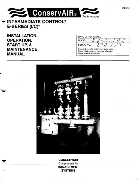
~ ConservAIR®<br />
.".."." Technologies<br />
.. INTERMEDIATE CONTROL®<br />
E-SERIES (I/C)®<br />
OM-CA-2<br />
INSTALLATION,<br />
OPERATION,<br />
START-UP, &<br />
MAINTENANCE<br />
MANUAL<br />
Record above information from name plate.<br />
Retain this information for future reference.<br />
Replacement Price $25.00<br />
r<br />
CONSERVAIR<br />
Compressed Air<br />
MANAGEMENT<br />
SYSTEMS<br />
_
1<br />
CONSERVAIR TECHNOLOGIES<br />
TABLE OF CONTENTS<br />
I. GENERAL INFORMATION 1<br />
II. INSPECTION 1<br />
III. SAFETY INSTRUCTIONS 1<br />
IV. INSTAl.l.ATION ~<br />
V. RECOMMENDED INSTALLATION DIAGRAM 3<br />
VI. START-UP & OPERATION 4<br />
VII. GENERAL ARRANGEMENT DRAWiNG 5<br />
VIII. CONTROL VALVE ASSEMBLY DRAWINGS 6, 7<br />
IX. SERVMATIC CONTROL DIAGRAM<br />
X. DIGITAL ADJUSTMENT CHART<br />
XI. OPTION DETAILS<br />
W XII. TROUBLE-SHOOTING GUiDE<br />
)(111. \nIARRANlr"<br />
8<br />
9<br />
10<br />
11, 12<br />
1~<br />
RECEIVING - INSPECTION<br />
Inspect equipment. Any concealed shipping damage must be<br />
reported to the carrier immediately. Damage claims should be<br />
filed by the consignee with the carrier.<br />
SAFETY INSTRUCTIONS<br />
When using air compressors and compressed air accessories,<br />
basic safety rules, and precautions must always be followed,<br />
including the following:<br />
1. READ ALL INSTRUCTIONS FULLY<br />
., ..... WARNING<br />
Air from compressor, Pneumatech Air Drying System, and<br />
ConservAir Intermediate Control as equipped, is NOT for human<br />
respiration (breathing).<br />
2. WIRING & BREAKERS<br />
Wiring, breakers, and other electrical equipment must<br />
conform to local and national electric codes. Do not<br />
operate this unit with damaged wiring after the unit or air<br />
handling parts have been dropped or damaged in any<br />
manner. Notify authorized service facility for examination,<br />
repair or other adjustments.
2<br />
I. INSTALLATION<br />
Your E-Series Intermediate Control Unit (I/C) has<br />
been air tested for functions and leaks and is ready<br />
for installation. ConservAIR suggests that a temporary<br />
or in-line strainer be installed on the inlet side<br />
of the I/C to guard against contaminants and insure<br />
proper operation.<br />
1) Inspect unit upon receipt. Immediately<br />
report any damage to the shipping<br />
carrier.<br />
2) The ConservAIR IIC Unit has an "IN"<br />
and "OUT" with directional flow arrows<br />
cast right into the Control Element.<br />
Orient the I/C unit in accordance with<br />
compressed air system flow.<br />
3) The ConservAIR IIC Unit can be<br />
installed in any plane. The headers are<br />
capable of supporting the weight of the<br />
unit for either vertical or horizontal<br />
mounting. DO NOT SUPPORT THE<br />
UNIT FROM THE CONTROL ELE<br />
MENTS OR THE ASSOCIATED<br />
CONTROL PIPING.<br />
7) Connect 115 VAC/Single Phase to the<br />
labeled terminal block. A lug is provided<br />
for grounding the control panel enclosure.<br />
The grounding lug is located next<br />
to the terminal block. Note for (I/C)<br />
units with the manual bypass<br />
option: Open the bypass located on<br />
the I/C header before applying<br />
power.<br />
8) Grounding: It is mandatory that the I/C<br />
control panel be grounded. Use an<br />
adequate ground with the conductor<br />
sized to NEC specifications.<br />
9) During shipments, wire connections<br />
may become loose. As recommended<br />
by U.L. specification, torque terminal<br />
screws inside enclosure to 20 in. Ibs.<br />
4) Mount the control panel where most<br />
convenient. The panel is designed for<br />
top connections. Do not exceed 150<br />
feet from the I/C header to the control<br />
panel.<br />
5) Pilot air tubing between the I/C header<br />
and the control panel is 1/4" 00. See<br />
the general arrangement drawing for<br />
control panel pneumatic connections.<br />
Install the CP-5, 40 micron filter, on the<br />
inlet control piping feeding the control<br />
panel.<br />
6) LEAK TEST: An air leak may develop<br />
during transportation or installation.<br />
Pressurize system and check for any<br />
leaks. The servo control line is<br />
extremely sensitive to leakage. This<br />
line must be bubble tight!
i\lI!!,fp'H $<br />
e<br />
--<br />
e<br />
T - TEMPERATURE GAUGE<br />
P - PRESSURE GAUGE<br />
R - RELIEF VALVE<br />
®<br />
AIR COOLED<br />
SEPARATOR<br />
~LE~ (R~,.)','ij'R'i;%<br />
..... Technologies<br />
ConservAIR® '<br />
~~ ~=-M<br />
"'2a..r~<br />
~aw<br />
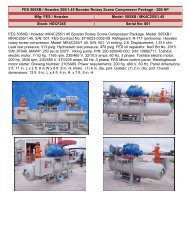
COMPRESSED AIR SYSTEMS<br />
RECOMMENDED INSTALLATION<br />
FLOW DIAGRAM ~<br />
T<br />
RECEIVER<br />
DIFFERENTIAL<br />
PRESSURE GAUGE<br />
OPTIONAL 3 VALVE<br />
SYSTEM BYPASS<br />
REFRIGERATED<br />
AIR DRYER<br />
- ~·O<br />
DIFFERENTIAL<br />
PRESSURE GAUGE<br />
---., ConservAIR -=<br />
TflchnologOl;J5<br />
INTERMEDIATE<br />
CONTROL<br />
AIR<br />
COMPRESSOR<br />
II<br />
11- ,,~n ~" I I<br />
.. - _..<br />
u<br />
WATER COOLED<br />
AFTERCOOLER<br />
COALESCING<br />
II<br />
AFTERFILTER<br />
4477<br />
II<br />
II<br />
AUTO<br />
II<br />
@<br />
DRAIN<br />
II<br />
DRAIN<br />
II<br />
II<br />
®<br />
4477<br />
AUTO<br />
DRAIN<br />
4<br />
II. START liP & OPERATION (See Control Panel Layout<br />
& General Arrangement Drawing)<br />
Prior to start up, check for unusual pressure drops<br />
between the compressor and the I/C unit. Ball<br />
valves located on the I/C should be open if option<br />
included. During start up, relief valves in the<br />
storage portion of the system may open. The air<br />
compressor system characteristics change after<br />
the I/C unit is put on line.<br />
The automatic bypass located on the I/C header is<br />
a fail safe open valve (spring openlair to close). If<br />
control air is disconnected from the automatic<br />
bypass or there is a power failure the automatic<br />
bypass will open. Important: Cycle the automatic<br />
bypass every three (3) months to insure proper<br />
operation.<br />
The control modules on the I/C header are fail<br />
closed valves. If control air (servo) is disconnected<br />
the valves will close. However, the control panel<br />
provides a servo signal to fully open the control<br />
valves in the event of a power failure. Isolation<br />
valves are provided to isolate each control module<br />
for maintenance.<br />
1) Turn the control panel power switch to<br />
the "off" position. Turning the control<br />
power off will insure that the automatic<br />
bypass opens. (For manual bypass<br />
option open the manual bypass located<br />
on the header.)<br />
2) Open the control panel door and turn<br />
the digital adjustment knob to a setting<br />
that is higher than the target discharge<br />
pressure. (This will insure that the<br />
control modules remain open when<br />
power is applied.) The digital adjustment<br />
knob comes equipped with a<br />
locking lever. Push the lever to the left<br />
to adjust the setting. A digital adjustment<br />
chart is located in the appendix<br />
and on the inside of the control panel<br />
door.<br />
3) Turn the control panel power switch to<br />
the "on" position. This will engage the<br />
ServMatic controller and close the<br />
automatic bypass. (For manual bypass<br />
option close the manual bypass located<br />
on the header.)<br />
4) Turn the digital adjustment knob<br />
counter clockwise to the desired discharge<br />
pressure. Turn the digital<br />
adjustment knob in small increments<br />
allowing the system to stabilize<br />
between adjustments. CAUTION!<br />
Failure to adjust the I/C in this manner<br />
may result in a system drawdown. The<br />
"AIR OUT" gauge displays discharge<br />
pressure of the I/C unit.<br />
5, 6, and 7 are Start up instructions for the AUTO<br />
BYPASS ONLY.<br />
5) The low pressure alarm is factory set at<br />
70 psig. If the discharge air pressure<br />
falls below 70 psig the auto bypass<br />
opens, the low pressure light illuminates,<br />
the bypass ready light turns off,<br />
and the buzzer resonates. The low<br />
pressure alarm is a latching alarm. To<br />
restore normal I/C operation the discharge<br />
pressure must rise above 78<br />
psig and an operator must press the<br />
low pressure reset button.<br />
6) The low pressure alarm is activated by<br />
a pressure switch located in the control<br />
panel. The pressure switch setting is<br />
adjustable from 10-100 psig. To change<br />
the low pressure alarm setting the I/C's<br />
discharge pressure must be lowered to<br />
the desired alarm set point. Then, the<br />
thumb wheel on the pressure switch is<br />
turned until the alarm activates. The<br />
thumb wheel is turned clockwise to<br />
increase the setting and counter-clockwise<br />
to decrease the setting.<br />
7) The automatic bypass has an<br />
adjustable travel stop to limit the valves<br />
opening when engaged. Set the<br />
opening for a fixed pressure drop of<br />
approximately 5 psig when the valve is<br />
open. This will provide a smoother transition<br />
if a low pressure alarm occurs<br />
and help prevent a possible compressed<br />
air drawdown situation. To set<br />
the opening position the bypass valve<br />
must be closed. An indicator is<br />
mounted on the actuator. When the<br />
indicator is perpendicular to the pipe<br />
run it is closed. Turn the bolt on the<br />
actuator clockwise to limit opening.<br />
When the bolt is full clockwise the valve<br />
is limited 100% and will not open. Full<br />
adjustable range is approximately 8<br />
turns.<br />
Maximum inlet pressure is 150 PSIG. Maximum<br />
regulating pressure is 145 PSIG.
INTERMEDIATE CONTROL<br />
W/AUTO BYPASS<br />
INTERMEOIA TE CONTROL<br />
W/MANUAL BYPASS<br />
5<br />
IILET<br />
AlR AIR AIR<br />
----7- ~ ~<br />
CJJTlET<br />
]ILET<br />
CUTLET<br />
FlLTEl<br />
Cf'-5<br />
Fll...lER<br />
CP-S<br />
All II<br />
TO I>JIt II ClUE<br />
ElCWUST<br />
~[]]]<br />
~<br />
iiS-i-60<br />
115-1-00<br />
ALL PNELMATIC CONTROL LINES ARE 1/4' 0.0.<br />
f---"-,---::=O:...:,,O-..:..;N-=...;OT,-S=C'"'-"AL=E'----=:-t----.---<br />
---i_J:l_B..,IO_---I GENERAL AR RA NGEMENT<br />
ALL lJn-elSI()G JJ1E IN IhO-ES<br />
ORA WING<br />
-$- -E}- f--+<br />
REy ---OESCRI--PTl-OH----t- t--'''-T-E---i~ Conserv AIR~T"""'rol""'~<br />
rRtU:CTI()I THlI\O #0.£ BY '-"" ",~'~ ~...... VV'v~<br />
UUSS Onel\ilSC 5I'£CIFlEl THIS [RA1JlI(; IJIO Sf'ECIFIC",T1GlS ME HE I'R(l'ERTI IF I'lEU1ATECH SCALE, _ DRA'vIING NO. REV.<br />
TCl..£IW(:ES<br />
DC. .I.I(J IIAY lOT IE CXJ'IH) te'RCDJCED, eft BE U5HJ IN IoIl-U.E CR<br />
ClIK3ffi()G +/- V~tl ((l.'\1wnl IN rMT. loS " &SIS Fal iE;IGN. w.K..FACTUlE. eft SALE \IllIOJT MC- 1()95 00<br />
Nn..E _ +/ - \. f'8MSSUJII FIDl f'1€U1,', TECH DC. t:J
6<br />
---<br />
I:EY<br />
PART NO.<br />
1. 37-199<br />
2. 37-197<br />
3. 37-202<br />
4. 37-205<br />
s. 37-73M-SRI95<br />
6.. 37-218<br />
7. 37-2 19M5 19S<br />
a 37-151<br />
9. 37-241<br />
Ie. 37-233<br />
11. 37-231<br />
12. 37-237<br />
13. 37-28<br />
14. 37-223<br />
IS. 37-221<br />
16. 37-208A<br />
17. 37-201M<br />
18.<br />
19.<br />
6eL.-esM<br />
37-1988<br />
01986<br />
L-1l49<br />
DESCRIPTION<br />
CAP<br />
VALVE SPRING<br />
VALVE a-RING<br />
CAP a-RING<br />
.-EAO<br />
RETAINING RING<br />
DOME<br />
SPRING<br />
PUSHUT FASTEJI::R<br />
Slft'ORT<br />
DIAPl-RAGM<br />
HOUER<br />
O-RING<br />
STEM O-RING<br />
RETAINERO x VI6W<br />
PILOT ~<br />
STEM<br />
SCREW<br />
VALVE<br />
ALLEN PLUG<br />
LABEL<br />
SW-ASSEMBLY on<br />
I<br />
I<br />
I<br />
I<br />
I<br />
1<br />
1<br />
1<br />
I<br />
1.37-237<br />
DIAPI-RAGM I<br />
ASSEMBLY I<br />
1<br />
1<br />
1<br />
I<br />
1<br />
A37-198BM 1<br />
VALVE 1<br />
ASSEMBLY<br />
1<br />
4<br />
4<br />
E£JEiJ------0<br />
NOTES,<br />
l. LUBRICATE DOME \.11TH PARKER<br />
a-LUBE PRIOR TO AN[) AFTER<br />
INSTALLAnON OF PISTON.<br />
2. ALL DIMENSIONS ARE IN INCHES<br />
DO NOT SCALE<br />
+ -E3<br />
rRO..ECTlOI ~ NQ.£<br />
INLET<br />
1-1/2' NPTCF) 1--_-1<br />
1@ @jS.00<br />
II<br />
~r_0 ~.-------rr-----..---r' __,<br />
~<br />
SERVO SIGNAL<br />
1/4" NPTCF)<br />
OUTLET<br />
1-1/2' NPT(Fl<br />
CF1200 ASSEMBLY ORAWlNG<br />
f------t------------+---+----j~\Conserv AIR~T<br />
rol",.,,~<br />
RE DESClUPTIOH BY DATE / --.,,'~ ~ , VV'V~
Ci37 [ 3.<br />
~<br />
7<br />
KEY PART NO. DESCRIPTlON SUB-ASSEMBLY OTY<br />
l. 37-93 O-RING 2-[/8 ID x 1/81,.1 I<br />
2. 37-92 a-RING 1-1/4 10 x 1/8\.1 1<br />
-<br />
37-84 VALVE. A37-84<br />
~<br />
4. 37-87 VALVE SEAT I<br />
17 5. 37-81-2 HEAD 1<br />
6. 37-90 a-RING 5 IO x l/8W I<br />
2<br />
7. 37-91 a-RING 3-7/8 10 x 3/161,..1 2<br />
8. 37-82t'F DOME (TEFLON eOA TEDJ 1<br />
9. 37-8311 PISTON<br />
~ I<br />
3<br />
la. 37-191 BIAS SPRING I<br />
11. 37-98 O-RING 1/4 ID x 1/81,../ 1<br />
4<br />
r"I<br />
12. 456-11 BREATHER ELEMENT 2<br />
L-'<br />
13. -- ---- -<br />
16 14. 37-99 RETAINING RING<br />
1<br />
~ 15. 130-21 O-RING 1/1 10 x 1/161,.1 1<br />
16. 37-89 VALVE STEM I<br />
17. 37-198 VALVE SPRING I<br />
18. 37-85F CAP (TEFLON COATEDJ I<br />
19<br />
19. L-1148 LABEL<br />
I<br />
2a. a 1986 ALLEN PLUG 4<br />
~<br />
\J<br />
~~I<br />
I<br />
@<br />
IN<br />
:~<br />
~/<br />
v-®<br />
if~v® /' ~<br />
~<br />
I<br />
"....<br />
~t-"<br />
~<br />
c::::c:::::J<br />
t<br />
SERVO SIGNAL<br />
114' NPTlF)<br />
NOTES,<br />
I. LUBRICATE DOME \.lITH PARKER<br />
a-LUBE PRIOR TO AND AFTER<br />
INSTALLATION OF FIST ON.<br />
2. ALL DIMENSIONS ARE IN INCHES<br />
DO NOT SCALE<br />
AI...J.. D~~~~~l!l1lOES<br />
0<br />
It-LET<br />
OUTLET<br />
2" NFTCF) 2' NFTlFJ<br />
e:t><br />
ct><br />
5.75<br />
, /'<br />
I<br />
t<br />
11<br />
~ /<br />
7<br />
rJ;638<br />
9<br />
~I<br />
II)<br />
I<br />
lel<br />
""-=:>/1<br />
INLET<br />
r<br />
OUTLET<br />
2' NFTIF) 2' NFTIFJ<br />
@<br />
@<br />
8<br />
1<br />
8.00<br />
IN<br />
OUT<br />
5.00 I I 5.00<br />
J<br />
LL~<br />
.KlB to.<br />
~ -dal<br />
ADDEO DE~lPTlONS TO ITEMS 8. 18 DJH 4-14-94<br />
t<br />
SERVO SIGNAL<br />
1/4' NFTIFJ<br />
CF 1600RS ASSEt"IBL Y ORA WING<br />
~\ConservAIR~<br />
PRlA.ECTIOli THIRD NQE<br />
REV DESCRIPTION B1 DATE TecIloologles<br />
\JlESS OTl£R'WISE SI'ECIFIEO HilS ou.loIlI«' AND SPEClFICHI()15 ME lIE I'Ra'ERlY IF f'NEU1AlECH SCALf, -<br />
TCl...El\AlCES<br />
lJC. All) !\AT t()T EE CO"IEO. REf'ROCUE), (»{ BE USEll IN \l1O..E III<br />
IAPRVU B1, (J;;1 !DRA\.IING NO. REV.<br />
-/- v~'" (d_ IN PART. 1>5 A BASIS FOR CESIGN. IoWLFAClUIE. ()l SALE 'w'IIH:XJT<br />
OJ/EIlSIOIlS _<br />
NlCLE -/-1' I'SlMISSION F!IO'i f'IEUo1ATECH INC.<br />
DAlE" 1-2'HH IDRAW'N BY, B.JS IHOA - 1161 0 1
8,---- -----,<br />
SERVO<br />
(MUST BE BUBBLE TIGHT<br />
TO CONTROL VALVE)<br />
r----;GAUGE<br />
3 6 G<br />
F<br />
S<br />
3<br />
0,0-5,0<br />
G<br />
0,0-5,0 VDC<br />
INPUT SIGNAL<br />
VDC<br />
SERVO SIGNAL<br />
EXHAUST<br />
AIR IN<br />
6<br />
I<br />
I<br />
(+ )S • (- )G •<br />
(+ )F<br />
•<br />
DIGITAL ADJUSTMENT<br />
INPUT SIGNAL<br />
r--<br />
~<br />
IN<br />
IN+ ~<br />
~<br />
2 V+<br />
15 VDC<br />
1 GND ~<br />
00,0-99,9% 4 0-15 VDC<br />
0-150 PSrG<br />
~<br />
3<br />
~<br />
I--<br />
~<br />
The ServMat1c poppet valves maid require cleaning if residue accumulates in<br />
the valves, Before cleaning the ServMatic circuit board, disconnect the power<br />
source and remove from the electrical enclosure, Cleaning of the poppet<br />
valves should be done on a clean dr\:J surface using a clean cloth,<br />
CAUTION: Each poppet valve is frequenc!,j tuned, If the diaphragm or metal<br />
O-ring is damaged, or lost, the valve will need to be rep laced,<br />
r--::-:---::::O:::::O=N=OT~SC:_:_;;AL:;:_:;E~:_t____,__---------+_-KJ-B___,NO___" ------j SERV MATIC CCiNT RCiL [lIAGRAM<br />
ALL Dil'E~lCJNSrME~~iN<br />
INCfi::S<br />
-$- --E3 01 ADDED CLEANING NOTE DJt1 9 17-96 ~\ConservAIR\~<br />
PR~cmlM TH~NoIGLE REV DESCRIPTION BY DA TE ./ -~_.'/~ J Tochnotogles<br />
lM..ESS OT~ISE SPEClFlEO THIS DRA.....ING AND SPECIFICATWNS ARE THE PROPERTY OF PNElA'4ATECH SCALE - I APRVD BY, .' ~. lORA WING NO, IREV,<br />
TOLERANCES INC, AND 'lAY NOT BE C
Cl'l<br />
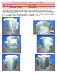
DIGITAL ADJUSTMENT CHART<br />
160<br />
140<br />
120<br />
-G'<br />
CI) 100<br />
e:,<br />
~<br />
;::,<br />
en<br />
en<br />
....<br />
ll..<br />
4)<br />
4) 80<br />
~<br />
.c<br />
en<br />
is<br />
(,) 60<br />
40<br />
20<br />
o<br />
V<br />
/<br />
/<br />
/' /<br />
/<br />
V<br />
/<br />
/<br />
./'/<br />
/<br />
00.0 10.0 20.0 30.0 40.0 ~o.o 60.0 70.0 80.0 90.0 99.9<br />
Digital Adjustment<br />
• t. .." 0 d- .. -p.<br />
/<br />
V<br />
/
10<br />
PRESSURE RESET OPTION for Manual Bypass VC's<br />
The Pressure Reset option allows the operator to<br />
change the I/C discharge setting via a local or<br />
remote switch.<br />
When the Pressure Reset switch is in the "on" position<br />
the Pressure Reset digital adjustment provides<br />
the control signal. In the "auto" position a remote<br />
switch must be used to activate the Pressure Reset<br />
option. The main digital adjustment and Pressure<br />
Reset digital adjustment are set the same way as<br />
described in the Start Up & Operation section.<br />
PRESSURE RESET OPTION for Auto Bypass IIC's<br />
The Pressure Reset option allows the operator to<br />
change the I/C discharge setting via a local or<br />
remote switch.<br />
REMOTE I LOCAL CONTROL OPTION for E Series<br />
Intermediate Control<br />
When the control panel selector switch is in the<br />
local position, use the digital adjustment to set the<br />
desired I/C discharge pressure.<br />
PRESSURE RANGE 0-150 psi<br />
When the control panel selector switch is in the<br />
remote position, a customer supplied 4-20 mA<br />
signal sets the desired I/C discharge pressure. A<br />
pressure transmitter may be installed on the I/C's<br />
outlet header to provide the process variable for a<br />
PID type control algorithm.<br />
INPUT SIGNAL 4-20 rna<br />
INPUT IMPEDANCE 625 ohm<br />
INPUT CURRENT LOOP POWER 15 vdc min.<br />
PRESSURE RANGE 25-125 psi<br />
When the Pressure Reset switch is in the "on" position<br />
the Pressure Reset digital adjustment provides<br />
the control signal. In the "auto" position a remote<br />
switch must be used to activate the Pressure Reset<br />
option. The main digital adjustment and Pressure<br />
Reset digital adjustment are set the same way as<br />
described in the Start Up & Operation section.<br />
A time delay relay is used to delay the pressure<br />
switch from triggering a low pressure alarm when<br />
switching from Pressure Reset mode to normal<br />
mode. <strong>Inc</strong>rease the delay time if the low pressure<br />
alarm activates prematurely.<br />
The Pressure Reset low pressure alarm is factory<br />
set at 50 psig. See Start Up & Operation section 5<br />
and 6 for procedure to change the Pressure Reset<br />
alarm setting. Note: the Pressure Reset option<br />
must be engaged to change the alarm setting.
~ .. ;~ .. 'i ..<br />
IV. TROUBLE-SHOOTING GUIDE<br />
SYMPTOMS<br />
A. Low IIC discharge pressure.<br />
SeNo gauge reads zero.<br />
CAUSE<br />
Pneumatic control tubing is leaking or<br />
damaged. (SeNo line is extremely sensitive to<br />
leaks.)<br />
REMEDY<br />
.:....::..====-.::..._---------<br />
Check for leak and repair as needed.<br />
B. High IIC discharge pressure.<br />
Control modules on header are stuck closed,<br />
internally leaking.<br />
SeNMatic is defective (see ServMatlc drawing).<br />
Auto bypass valve is open.<br />
Manual bypass valve is open.<br />
SeNMatic is defective. (see ServMatic drawing).<br />
Remove auto bypass valve control line to<br />
open bypass (caution: line is pressurized and<br />
will continuously vent air). Close control<br />
module isolation ball valves. SeNo gauge<br />
should increase in pressure. Check for leak<br />
and repair as needed. Open isolation ball<br />
valves. Reattach auto bypass control line.<br />
Open the manual bypass located on the IIC<br />
header. Close control module isolation ball<br />
valves. SeNo gauge should increase in pressure.<br />
Check for leak and repair as needed.<br />
Open isolation ball valves. Close the manual<br />
bypass.<br />
ServMatic test points F, G should read<br />
0-5 VDC for Digital Adjustment setting<br />
00.0-99.9%. Test points S, G should read the<br />
same as F, G. Clean, repair or replace.<br />
Inlet and outlet gauges read the same pressure.<br />
Check if bypass solenoid is closed<br />
andlor deenergized. Repair or replace the<br />
bypass solenoid. Check if there is sufficient<br />
pressure to close the auto bypass valve.<br />
Repair or replace the bypass actuator.<br />
Inlet and outlet gauges read the same pressure.<br />
Close the manual bypass.<br />
ServMatic test points F, G should read<br />
0-5 VDC for Digital Adjustment setting<br />
00.0-99.9%. Test points S, G should read the<br />
same as F, G. Clean, repair or replace.<br />
Control modules are stuck open, relieving<br />
excessive air.<br />
Check modules for contamination. Clean,<br />
repair, or replace.<br />
.....<br />
.....
"'""<br />
IV. TROUBLE-SHOOTING GUIDE (Cont.)<br />
....<br />
IV<br />
SYMPTOMS<br />
..=.C.:....:A=U.=S=E<br />
_<br />
REMEDY<br />
C. Low I/C discharge pressure in alarm<br />
mode.<br />
Auto bypass valve is closed.<br />
Check if bypass solenoid is open and/or energized.<br />
Repair or replace bypass solenoid.<br />
Bypass valve is sticking to its seat. Clean,<br />
repair, or replace bypass valve. Bypass actuator<br />
is defective. Repair or replace bypass<br />
actuator.<br />
D. Control modules exhaust excessive air<br />
while IIC in the alarm mode.<br />
Check valves are leaking.<br />
Check valves for contamination. Clean, repair,<br />
or replace.<br />
Control modules are stuck open.<br />
Check modules for contamination. Clean,<br />
repair, or replace.<br />
E. No I/C control panel power.<br />
Fuse is blown.<br />
Replace<br />
Disconnect is defective (if option included).<br />
Repair or replace<br />
F. Unstable discharge pressure.<br />
Inlet air pressure is within 4 psig of discharge<br />
air pressure set point.<br />
Pneumatic "servo" control line and/or fittings<br />
are leaking. This line should be bubble tight.<br />
ServMatic is defective. (see ServMatic drawing).<br />
Control modules are contaminated and/or<br />
have torn or cracked o-rings.<br />
<strong>Inc</strong>rease inlet air pressure and/or decrease<br />
discharge air pressure set point.<br />
Check for leak from ServMatic circuit board to<br />
each control module. Repair leak.<br />
ServMatic test points F, G should read 0-5<br />
VDC for Digital Adjustment setting 00.0<br />
99.9%. Test points S, G should read the same<br />
as F, G. Clean, repair or replace.<br />
Clean, repair, or replace (Note: for CF1600<br />
control module, replace o-ring 130-21.)<br />
e ~
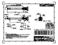
I<br />
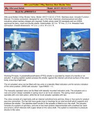
~E------41.5"------<br />
EJ<br />
23,0"<br />
AIR<br />
------<br />
IN<br />
AIR<br />
--<br />
OUT<br />
®<br />
1. 2" Control Module<br />
2, 2" Ball Valve<br />
3. 2" Union<br />
4, 2" Check Valve<br />
5, 3" Header<br />
6, 1/4" NPT Cou ling<br />
7, 2" Butterfl~ Valve<br />
8, 2" Half Coupling<br />
9, 3" 150# R.Ft Flange<br />
Note:<br />
1. Depth: 15"<br />
2. Approximate Weight: 170 LBS.<br />
3, A11 Dimensions Are In <strong>Inc</strong>hes<br />
\<br />
~N:~Do:rut~I~EE~~-----------I-.XJ-B-.IO---1E3-2C2A2 WELDED<br />
IMENSICtlS .... +/: 1/11n 01 AIUJ5TED D1I'ENSJIJIS AS BULT lUI 3-2-95 Intermedl te Control<br />
.•. +/ 4mm ~Xl \/'::::'--/<br />
HOLE ~. +/-1" REV DESCRIPTION BY DATE ~\Conserv AIR~~
~================:;==r==========::::::;::======:::;=:::::;::;l<br />
KEY DESCRIPTION SUB-ASSEMBL Y QTY<br />
1. O-RING 2-lIS ID x liS'" 1<br />
r-=2 ::c..'-+-=O:..--.:....:R;::c:.1N.:.::G:........::.,l--=1:..-/.....;.4.....;.I:..=D,---,-,x......:...1/....;;S.....;."'..--.., C-116 1<br />
3. O-RING 5 In x liS'" VAL VE 1<br />
4 :"-.--+-=O'---R':""IN-G-3--7-/-S-I-D-x-3-/-16-",---I 0 -RING 2<br />
5. O-RING 114 In x liS'" KIT I JA~~E 1<br />
r-=6:..:...-+-=O:..--.:....:R::..:.IN.:.::G:..-:..:1I_4~I=-D -=x-,----"l,;..../::..:16:....:."'=-----+__--1 REPAIR 1<br />
7. VALVE KIT 1<br />
S. VALVE SEAT 1<br />
9. RETAINING RING 1<br />
10. VALVE STEM 1<br />
11. VAL VE SPRING 1<br />
12. HEAD<br />
13. DOME (TEFLON COATED)<br />
14. PISTON<br />
15. BIAS SPRING<br />
16. CAP <br />
17. ALLEN PLUG 4<br />
_IN__~<br />
INLET<br />
2' NPT<br />
r 6.13<br />
1156]I<br />
[ I ] 1<br />
~=<br />
I<br />
,.....,<br />
OUTLET lJ)<br />
2' NPT '-'<br />
r<br />
INLET OUTLET<br />
2' NPT(D<br />
r<br />
2' NPT
7,0<br />
NOTES:<br />
AIR IN AIR OUT 1. DEPTH 8,0"<br />
2. ALL Dlt'IENSIONS ARE<br />
IN INCHES<br />
~\C_on5ervAIR\~<br />
, ,,,,\.., ----"-----J,..,} Technologies<br />
20.0<br />
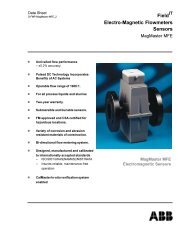
Power Bypass Low Pressure<br />
· I On I I Ready Alarm/Reset<br />
"" /<br />
0 "- }tJ" ©<br />
/<br />
Power<br />
I Off On<br />
@<br />
Hasp<br />
16,0 ---------=;>~I<br />
NEMA 12 ENCLOSURE WITH HINGED DOOR<br />
AND LOCKABLE HASP<br />
mN:~DOt~~~IijEEs 02 flEHO't13) NOTE FROM PANa :..':+-97 LOW PRESSURE CONTROL PANEL<br />
IMENSIOOS .... +/-I/1ln<br />
ARRANGEMENT<br />
... +/-4mm 01 CHANJ8) f"O'WER C»I / CFF LAllEl D-H 11-29-93 r:::---/<br />
HOLE .... +/_1° REV DESCRlPTION BY DIITE ~\COn5erV AIR\~<br />
_r---l<br />
IS ORAWOO A/() SPECIFICATIONS ARE nE P~TY IF<br />
+ ---c.::::.::r- TECH ItC ANO ~y NOT BE OO'IBl. REPROOlX::Bl. ~ BE SCALE. - APRIIO BY, ORA'WING NO. REV.<br />
-$ _<br />
aJ IN WHOLE O~ IN f'A~T. /IS A BASlS Fe« DESIGN, M~AC- PA 10018 02<br />
PIlOJECTIC»II THIRD AN3LE • CR SALE WITI-D.JT PRICR PERMISSION FROM f'IIELHATECH INC. DATE. 8-21-92 DRAWN BY, B.L. - tJ
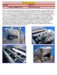
AIR IN BYPASS SERVD AIR OUT<br />
~<br />
2 PORT<br />
20,0<br />
...<br />
EXHAUST<br />
PRESSURE<br />
I -----+------+---J'<br />
SIJITCH<br />
~:=:=:=:±==~--<br />
ServHotlc<br />
I'<br />
I'<br />
I I<br />
I'<br />
I' ,I<br />
,I CONTACT. CONTACT [R]<br />
BlOCK<br />
BlOCK<br />
,I ITDJITDJ 0<br />
Ii<br />
_-J.j<br />
DIGITAL<br />
ADJUSTMENT<br />
i----------------l<br />
CONTROL<br />
RELAY<br />
FUSE-O.5A<br />
DGROUND 1<br />
TERMINAL BLOCK<br />
I.<br />
"<br />
16,0<br />
sou - SERVO SOLENOID VALVE<br />
SOL2 - BYPASS SOLENOID VALVE<br />
, NEMA 12 ENCLOSURE VITH HINGED DOOR<br />
AND LOCKABLE HASP
115V-IPH-60HZ<br />
L1<br />
I<br />
I<br />
I<br />
GND<br />
i<br />
I<br />
I<br />
/ '\.<br />
POler On Light<br />
RtA-fIJ<br />
Servo Solenoid Vo.lve<br />
LOl Pressure Light<br />
2<br />
Bypo.ss Solenoid Vo.lve<br />
BypllsS Reo.dy Light<br />
RIB-fIJ<br />
EXHAUST<br />
SERVO<br />
AIR IN<br />
. 12<br />
+<br />
PO'w'ER<br />
SOURCE<br />
15VDC<br />
13<br />
CIRCUIT<br />
BOARD<br />
4<br />
G)<br />
®<br />