colorado/canyon s/t pu and chassis-cab 43 - GM UPFITTER
colorado/canyon s/t pu and chassis-cab 43 - GM UPFITTER
colorado/canyon s/t pu and chassis-cab 43 - GM UPFITTER

You also want an ePaper? Increase the reach of your titles
YUMPU automatically turns print PDFs into web optimized ePapers that Google loves.
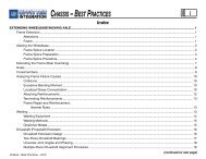
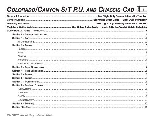
COLORADO/CANYON S/T P.U. AND CHASSIS-CAB<br />
PAGE<br />
i<br />
General Information ............................................................................................................... See “Light Duty General Information” section<br />
Camper Loading ............................................................................................................. See Online Order Guide — Light Duty Information<br />
Trailering Information ......................................................................................................... See “Light Duty Trailering Information” section<br />
Model <strong>and</strong> Option Weights ......................................................... See Online Order Guide — Model & Option Weight–Weight Calculator<br />
BODY BUILDERS INSTRUCTIONS .................................................................................................................................................................. 1<br />
Section 0 – General Instructions ...............................................................................................................................................................1<br />
Section 1 – Body ..........................................................................................................................................................................................2<br />
Air Conditioning ....................................................................................................................................................................................2<br />
Section 2 – Frame........................................................................................................................................................................................3<br />
Flanges ..................................................................................................................................................................................................3<br />
Holes .....................................................................................................................................................................................................3<br />
Welding .................................................................................................................................................................................................3<br />
Alterations .............................................................................................................................................................................................4<br />
Shear Plate Attachments ......................................................................................................................................................................4<br />
Section 3 – Front Suspension ....................................................................................................................................................................4<br />
Section 4 – Rear Suspension .....................................................................................................................................................................5<br />
Section 5 – Brakes ......................................................................................................................................................................................5<br />
Section 6 – Engine .......................................................................................................................................................................................6<br />
Section 7 – Transmission ............................................................................................................................................................................7<br />
Section 8 – Fuel <strong>and</strong> Exhaust.....................................................................................................................................................................8<br />
Fuel Systems ........................................................................................................................................................................................8<br />
Fuel Lines ..............................................................................................................................................................................................8<br />
Fuel Tank ...............................................................................................................................................................................................9<br />
Exhaust System ....................................................................................................................................................................................9<br />
Section 9 – Steering ..................................................................................................................................................................................10<br />
Section 10 – Tires ......................................................................................................................................................................................11<br />
2004 <strong>GM</strong>T355 – Colorado/Canyon – Revised 06/2009
Colorado/Canyon S/T P.U. <strong>and</strong> Chassis-Cab<br />
BODY BUILDERS INSTRUCTIONS – (Continued)<br />
Section 12 – Electrical Battery <strong>and</strong> Battery Cables...............................................................................................................................11<br />
Accessory Power Supply Feed:..........................................................................................................................................................12<br />
Section 13 – Cooling..................................................................................................................................................................................13<br />
Model Symbol Chart..........................................................................................................................................................................................14<br />
VEHICLE GENERAL ARRANGEMENT<br />
S/T15403 .....................................................................................................................................................................................................15<br />
S/T15653 .....................................................................................................................................................................................................16<br />
S/T156<strong>43</strong> .....................................................................................................................................................................................................17<br />
S/T15603 .....................................................................................................................................................................................................18<br />
PICKUP WEIGHT DISTRIBUTION<br />
Regular Cab Pickup – S/T15403..............................................................................................................................................................19<br />
Extended Cab Pickup – S/T15653............................................................................................................................................................20<br />
Crew Cab Pickup – S/T156<strong>43</strong>...................................................................................................................................................................21<br />
Regular Chassis-Cab – S/T15603............................................................................................................................................................22<br />
BODY<br />
EXTERIOR<br />
Pickup: General Arrangement – S/T15403 .....................................................................................................................................23<br />
Pickup: General Arrangement – S15653 ........................................................................................................................................24<br />
Pickup: General Arrangement – T15653 ........................................................................................................................................25<br />
Pickup: General Arrangement – S/T156<strong>43</strong> .....................................................................................................................................26<br />
Chassis-Cab: General Arrangement – S/T15603 ..........................................................................................................................27<br />
Cab – Crew (<strong>43</strong>) – H/L/W, Hood Opening, Rear Window..............................................................................................................28<br />
Door Swings – Extended Cab (53)...................................................................................................................................................29<br />
Door Swings – Crew Cab (<strong>43</strong>)..........................................................................................................................................................30<br />
Cab, Rear Profile – Regular (03)......................................................................................................................................................31<br />
PAGE<br />
ii<br />
2004 <strong>GM</strong>T355 – Colorado/Canyon – Revised 06/2009
Colorado/Canyon S/T P.U. <strong>and</strong> Chassis-Cab<br />
BODY, EXTERIOR — Continued<br />
Cab, Rear Profile – Extended (53)....................................................................................................................................................32<br />
Cab, Rear Profile – Crew (<strong>43</strong>)...........................................................................................................................................................33<br />
Hood Profile .......................................................................................................................................................................................34<br />
Front End Sheet Metal......................................................................................................................................................................35<br />
Pickup Box, Tie Down Loops, Bulkhead Dividers, Two Tier Loading, PU Box Top..................................................................36<br />
Pickup Box, Tie Down Loops, Bulkhead Dividers, Two Tier Loading, PU Box Top..................................................................37<br />
Pickup Box, Tie Down Loops, Bulkhead Dividers, Two Tier Loading, PU Box Top..................................................................38<br />
Pickup Box, Tie Down Loops, Bulkhead Dividers, Two Tier Loading, PU Box Top..................................................................39<br />
INTERIOR<br />
Cab Interior – Regular Cab (03).......................................................................................................................................................40<br />
Cab Interior – Extended Cab (53)....................................................................................................................................................41<br />
Cab Interior – Crew Cab (<strong>43</strong>)............................................................................................................................................................42<br />
Seating Positions (03 & 53)...............................................................................................................................................................<strong>43</strong><br />
Seating Positions (<strong>43</strong>).......................................................................................................................................................................44<br />
CHASSIS<br />
FRAME AND CROSSMEMBER ARRANGEMENT<br />
Frame <strong>and</strong> Crossmember – S/T154 (03) Regular Cab Pickup.....................................................................................................45<br />
Frame <strong>and</strong> Crossmember – S/T156 (<strong>43</strong>) Crew Cab Pickup.........................................................................................................46<br />
Frame <strong>and</strong> Crossmember – S/T156 (53) Extended Cab Pickup..................................................................................................47<br />
Frame <strong>and</strong> Crossmember – S/T156 (03) Regular Cab Chassis-Cab...........................................................................................48<br />
SPARE TIRE<br />
Spare Tire Location (compact) S Truck..........................................................................................................................................49<br />
Spare Tire Location (full size) T Truck............................................................................................................................................50<br />
TRAILER HITCH<br />
Factory Installed Trailer Hitch, Option VR4....................................................................................................................................51<br />
PAGE<br />
iii<br />
2004 <strong>GM</strong>T355 – Colorado/Canyon – Revised 06/2009
Colorado/Canyon S/T P.U. <strong>and</strong> Chassis-Cab<br />
AXLE SUSPENSION<br />
Front Axle / Tire Data..........................................................................................................................................................................52-54<br />
Rear Axle / Tire Data...........................................................................................................................................................................55-58<br />
FUEL SYSTEMS<br />
S/T15403 & S/T15603 & S/T15653............................................................................................................................................................59<br />
S/T156<strong>43</strong> .....................................................................................................................................................................................................60<br />
EXHAUST SYSTEMS<br />
Exhaust System S15403 ...........................................................................................................................................................................61<br />
Exhaust System T15403............................................................................................................................................................................62<br />
Exhaust System S156 (03/<strong>43</strong>/53)..............................................................................................................................................................63<br />
Exhaust System T156 (03/<strong>43</strong>/53) .............................................................................................................................................................64<br />
Exhaust System S/T15653 & S/T156<strong>43</strong> with 5.3L V8 Option LH9........................................................................................................65<br />
Tailpipe Locations S/T 15 (000)................................................................................................................................................................66<br />
PAGE<br />
iv<br />
2004 <strong>GM</strong>T355 – Colorado/Canyon – Revised 10/2009
Colorado/Canyon S/T P.U. <strong>and</strong> Chassis-Cab<br />
BODY BUILDERS INSTRUCTIONS<br />
PAGE<br />
<br />
The Incomplete Vehicle Document (IVD) is supplied with each incomplete vehicle, <strong>and</strong> provides information that should be used by<br />
intermediate <strong>and</strong> final stage manufacturers in determining conformity to appli<strong>cab</strong>le Federal Motor Vehicle Safety St<strong>and</strong>ards (FMVSS).<br />
The IVD also includes information which must be followed in order to ensure that Environmental Protection Agency (EPA) <strong>and</strong> California<br />
emissions certification requirements <strong>and</strong> NHTSA Fuel Regulations are met.<br />
The Body Builders Manual contains information that may be used in addition to the IVD for any manufacturer making alterations to a<br />
<strong>GM</strong> complete/incomplete vehicle. No alteration should be made to the incomplete vehicle which either directly or indirectly results in<br />
any component, assembly or system being in nonconformance with any appli<strong>cab</strong>le Federal Motor Vehicle Safety St<strong>and</strong>ard or Emission<br />
Regulation. Intermediate <strong>and</strong> final stage manufacturers should be familiar with all Federal Motor Vehicle Safety St<strong>and</strong>ards <strong>and</strong> Emission<br />
Regulations <strong>and</strong> aware of their specific responsibilities as manufacturers.<br />
For further assistance contact Upfitter Integration at: 1 (800) 875-4742, or go to our Web site at “http://www.gmupfitter.com.”<br />
Section 0 — General Instructions<br />
Check for proper clearance between body members <strong>and</strong> <strong>chassis</strong> components which may in any way affect the reliability <strong>and</strong> performance<br />
of the vehicle by developing abrasion <strong>and</strong> wear points from moving parts or degradation from extreme environment or thermal exposure<br />
or may increase interior noise.<br />
Check headlamp aim <strong>and</strong> all vehicle illumination systems for proper operation when the vehicle has been completed. Re-aim headlamps<br />
when necessary. Check for proper operation of windshield washer, wipers <strong>and</strong> defroster system.<br />
Extreme care must be taken when working on vehicles equipped with Powertrain Control Module (PCM), Body Control Module (BCM) or<br />
any electronic unit associated with an inflatable restraint system. (See Owner’s Manual).<br />
If arc-welding is employed on the <strong>chassis</strong>, precautions must be taken to protect all vehicle components, especially brake, fuel lines <strong>and</strong><br />
fuel tank assembly, electrical wiring <strong>and</strong> ECM/PCM/TCM or BCM. To avoid electronic component damage, disconnect battery (batteries);<br />
disconnect the negative <strong>cab</strong>le first, followed by the positive. To reconnect <strong>cab</strong>les; connect the positive first, then the negative.<br />
When welding components to the frame assembly, remove the wax coating in the area of the weld in order to obtain secure welds. After<br />
completion of the weld, a compatible corrosion protection should be applied to the affected weld areas.<br />
All labels on the vehicle (any message applied to the vehicle or vehicle component that informs, instructs, or warns) must appear on the<br />
completed vehicle so the user can read them easily <strong>and</strong> without obstruction.<br />
2004 <strong>GM</strong>T355 – Colorado/Canyon<br />
(Section 0 — continued on next page)
Colorado/Canyon S/T P.U. <strong>and</strong> Chassis-Cab<br />
PAGE<br />
<br />
(Section 0 — continued from previous page)<br />
Service <strong>and</strong> service replacement parts for your add-on systems may not be available from a <strong>GM</strong> dealer. Those installing aftermarket systems<br />
should provide information as to where <strong>and</strong> how to obtain service.<br />
Section 1 — Body<br />
Body structures, interior <strong>and</strong> accessory arrangements must be designed into the vehicle to provide for proper load distribution on both axles<br />
<strong>and</strong> not to exceed any gross axle weight ratings. Lateral load equalization must also be maintained. The resultant Center of Gravity of the<br />
unladen vehicle must be within the limits tabulated in the FMVSS 105 section of the Incomplete Vehicle Document.<br />
Body insulation provided by General Motors should not be removed. This includes any thermal or underbody heat shields. This insulation is<br />
provided to protect the vehicle body <strong>and</strong> occupants from excessive heat <strong>and</strong>/or provide noise attenuation. Any replacement material internal<br />
to the occupant compartment must be certified for MVSS st<strong>and</strong>ard on flammability. Areas of specific concern, but not limited to, are:<br />
• Underbody exhaust, muffler <strong>and</strong> tail pipe shields <strong>and</strong> insulators.<br />
• Front floor interior insulation.<br />
• Dash mat insulation.<br />
• Engine cowl insulation – interior <strong>and</strong> exterior.<br />
If body builder installs seating other than that supplied with vehicle, it is the body builder’s responsibility to ensure that the seating <strong>and</strong><br />
restraint systems comply with FMVSS requirements. The restraint systems supplied with the vehicle were designed to accommodate the<br />
seating reference points <strong>and</strong> seat travel of the original equipment seats only.<br />
Air Conditioning<br />
For additional information refer to Engine – Section 6.<br />
NOTE: Air conditioning systems using R-134A refrigerant are equipped with metric fittings to prevent interchange with R-12 refrigerant<br />
components. Do not interchange R-134A components, refrigerant oil or service equipment with R-12 components, refrigerant oil or<br />
service equipment.<br />
2004 <strong>GM</strong>T355 – Colorado/Canyon
Colorado/Canyon S/T P.U. <strong>and</strong> Chassis-Cab<br />
Section 2 — Frame<br />
PAGE<br />
<br />
Hole drilling, welding, modifications, or alterations to the frame assembly are the responsibility of persons performing these operations.<br />
These same individuals assume complete responsibility for frame assembly reliability, performance after alterations <strong>and</strong> compliance to<br />
appli<strong>cab</strong>le FMVSS requirements.<br />
The following procedures <strong>and</strong> specific precautionary instructions are recommended for proper installation of special bodies <strong>and</strong>/or equipment<br />
on <strong>GM</strong> frames. Failure to follow these recommendations could result in serious damage to the basic vehicle.<br />
Flanges<br />
Do not drill holes in frame flanges.<br />
Holes<br />
Holes to mount brackets, supports, <strong>and</strong> out-riggers must be drilled in the vertical side rail web with the following restrictions:<br />
• Material between edge of hole <strong>and</strong> inside of upper or lower flange must not be less than 37 mm (1.50 in.) for low carbon steel<br />
(36,000 PSI yield).<br />
• The minimum edge distance between any two (2) holes must be larger than twice the diameter of the larger hole.<br />
• No holes should exceed 20 mm (0.75 in.) in diameter.<br />
• All holes should be drilled in the frame using appropriate drilling practice <strong>and</strong> safety precautions.<br />
Welding<br />
CAUTION: Fueltank <strong>and</strong> fuel lines must be drained <strong>and</strong> all vapors <strong>pu</strong>rged to ensure noncombustible mixture before any welding, brazing<br />
or soldering.<br />
When welding low carbon steel side rails, crossmembers <strong>and</strong> brackets (32,000 or 36,000 PSI yield strength), emphasis is placed upon weld<br />
application techniques to avoid stress risers that may adversely affect frame operating stresses.<br />
When welding is performed anywhere on the vehicle, precautionary measures should be taken to prevent damage to electrical system<br />
wiring or components. Prior to any welding, parts or components which could be damaged by excessive temperatures must be removed or<br />
adequately shielded; the battery <strong>cab</strong>les should be disconnected at the battery. Also prior to welding, the area to be welded <strong>and</strong> surrounding<br />
area must be cleaned of all frame protective coating. After welding, when parts are cool, carefully inspect wiring <strong>and</strong> electrical components.<br />
2004 <strong>GM</strong>T355 – Colorado/Canyon<br />
(Section 2 — continued on next page)
Colorado/Canyon S/T P.U. <strong>and</strong> Chassis-Cab<br />
(Section 2 — continued from previous page)<br />
for shorts or other damage which could draw excessive currents <strong>and</strong> possibly cause an electrical system short when the battery is<br />
reconnected. Apply protective coating to areas where coating was removed.<br />
Alterations<br />
If the wheelbase is modified the alterer must take responsibility for compliance with affected motor vehicle safety st<strong>and</strong>ards <strong>and</strong> for warranty<br />
on items such as driveshafts, universal joints, center bearings <strong>and</strong> rear transmission tailshaft, transfer case <strong>and</strong> transmission case fractures,<br />
out<strong>pu</strong>t shaft bushings, bearings, brakes, fuel systems <strong>and</strong> any other related component failures. Additionally, the customer must be alerted<br />
in the modifier’s owner’s manual that parts for the reworked area are not available through the General Motors service parts system.<br />
Shear Plate Attachments<br />
Attachments of shear plates should be accomplished by using existing manufacturing holes already available in the frame side rails. Manufacturing<br />
holes, normally 16 mm in diameter, are consistently placed along the frame side member in the center of the web on each frame.<br />
When additional holes are required for shear plate attachment, they should be no larger than 20 mm (0.75 in.) in diameter. Holes are to be<br />
drilled no closer than 63.5 mm (2.5 in.) apart. For holes drilled forward of the rear axle, centers are to be no closer than 63.5 mm (2.5 in.)<br />
from the top or bottom flanges <strong>and</strong> no closer than 89 mm (3.5 in.) from any suspension attachments. For frame holes drilled rearward of<br />
the rear axle, hole centers are to be no closer than 51 mm (2.0 in.) from the top or bottom flange <strong>and</strong> no closer than 89 mm (3.5 in.) from<br />
suspension attachments.<br />
No additional holes or notching of either top or bottom frame flanges is allowed.<br />
Rear bodies or platforms added to the vehicle must utilize the released attachment points used by the pick-up box, along with fasteners of<br />
the same diameter. These are minimum requirements; additional fasteners are permissible.<br />
Section 3 — Front Suspension<br />
See <strong>chassis</strong> data information for clearances <strong>and</strong> assistance in calculating trim heights.<br />
Since there is a large variation in completed vehicle front weight due to differences in body weight <strong>and</strong> equipment, the front suspension<br />
alignment must be checked <strong>and</strong> reset if necessary after the vehicle is completed. Caster <strong>and</strong> camber should be set with reference to the<br />
“A” dimensions.<br />
See Truck Service Manual for complete alignment procedure, specifications <strong>and</strong> measurement of the “A” dimension under “Diagnosis <strong>and</strong><br />
Front Alignment” section.<br />
2004 <strong>GM</strong>T355 – Colorado/Canyon<br />
PAGE
Colorado/Canyon S/T P.U. <strong>and</strong> Chassis-Cab<br />
Section 4 — Rear Suspension<br />
PAGE<br />
<br />
Clearance to body should be provided for the suspension, axle, driveshaft <strong>and</strong> tires under the following conditions: (1) Axle in full jounce<br />
against the metal-to-metal stop, (2) Axle at 4.5˚ roll with one side of axle in full jounce at the metal-to-metal stop <strong>and</strong> (3) Axle at design<br />
position. Allowance for the tire chain clearance shown on a maximum grown tire must allow for (1.66 in.) clearance to the sides of the tire<br />
<strong>and</strong> (2.5 in.) to the top of the tire. Be sure sufficient clearance is provided for suspension, axle <strong>and</strong> tire <strong>and</strong> wheel in full vertical travel (up<br />
<strong>and</strong> down).<br />
NOTE: Notification to the consumer may be required in certain states if tire chains cannot be used.<br />
Pipes, wiring, conduits <strong>and</strong> any other related components must not be placed where they cross the path of motion of the rear axle, driveshaft,<br />
axle brake pipes, hoses, spring or tires. Such crossing could result in rupture, wear through, or separation due to normal axle motion.<br />
See <strong>chassis</strong> data information for additional clearances <strong>and</strong> for assistance in calculating trim heights.<br />
See Truck Service Manual for brake specifications.<br />
Section 5 — Brakes<br />
Due to the critical nature of brake systems, anyone making modifications or alterations must assume complete responsibility for system<br />
reliability, performance <strong>and</strong> certification to FMVSS 105 or FMVSS 121.<br />
It is m<strong>and</strong>atory that no change be made to the brake main cylinder location, brake pedal <strong>pu</strong>sh rod length or pedal position.<br />
Ensure that hydraulic brake system is free of air <strong>and</strong> hydraulic leaks. Bleed brakes if required, following procedures as outlined in truck<br />
<strong>chassis</strong> service manual. Ensure that vacuum booster system or hydroboost system is functional <strong>and</strong> free of leaks.<br />
Check master cylinder fluid level <strong>and</strong> fill as necessary. (Refer to Owner’s Manual).<br />
Check power steering fluid level for models equipped with hydroboost brake. (Refer to Owner’s Manual).<br />
Added floor covering or carpeting must not restrict service or parking brake pedal travel from released position to full pedal travel.<br />
No body part or <strong>chassis</strong>-mounted component may be located within 2.0 in. of brake hose routing in all wheel <strong>and</strong> axle positions. All exhaust<br />
system components must also have a minimum of 2.0 in. clearance to brake hoses in closest positions. (Be sure to account for brake hose<br />
travel with suspension).<br />
2004 <strong>GM</strong>T355 – Colorado/Canyon<br />
(Section 5 — continued on next page)
Colorado/Canyon S/T P.U. <strong>and</strong> Chassis-Cab<br />
(Section 5 — continued from previous page)<br />
Body builder is to verify that the brake warning switch is operative. The brake warning switch on models equipped with vacuum-hydraulic<br />
brakes is located adjacent to the master cylinder vacuum unit. This includes both the brake system differential pressure <strong>and</strong> parking brake<br />
actuator switch.<br />
For additional information refer to Body – Section 1.<br />
Section 6 — Engine<br />
Air conditioning <strong>and</strong> auxiliary belt-driven equipment installation recommendations:<br />
No alterations or additions to the accessory drive belt system will be warranted on serpentine belt systems.<br />
The serpentine belt type of drive is designed as a total system, incorporating a single poly-V belt <strong>and</strong> an automatic tensioner. In this type of<br />
system, degrees of <strong>pu</strong>lley wrap, belt tension, <strong>and</strong> <strong>pu</strong>lley alignment are very critical factors. Modification is not recommended.<br />
In some single belt serpentine systems, belt tension is determined by the automatic tensioner <strong>and</strong> its position relative to the belt. No<br />
adjustment is required.<br />
Due to the critical nature of the accelerator system, anyone making modifications or alterations assumes complete responsibility for<br />
system reliability, performance <strong>and</strong> compliance to FMVSS 124. Caution must be exercised so that the accelerator <strong>cab</strong>le is properly routed.<br />
Specifications are as follows:<br />
• Route <strong>cab</strong>le to maximize all bend radii. In no case should bend radii be less than 3 in. (76 mm).<br />
• Minimum distance from exhaust manifold to be 6.0 in. (150 mm), unless a heat shield is provided.<br />
• Do not use accelerator <strong>cab</strong>le or clips to route wires, harnesses or other <strong>cab</strong>les. Cable sheath must be clipped so as not to pinch<br />
inner <strong>cab</strong>le. Cable must not be loose in clip allowing sheath to move when accelerator pedal is applied <strong>and</strong> released.<br />
• Cable must not be subjected to kinking or routing across any sharp edges.<br />
• Cable routing must be perpendicular to the surface of the front-of-dash at the dash fitting. No objects or routings should force<br />
<strong>cab</strong>le to have a bend at the dash fitting. Flexible components (hoses, wires, conduits, etc.) must not be routed within 2.0 in.<br />
(50 mm) of moving parts or accelerator linkage unless routing is positively controlled.<br />
PAGE<br />
<br />
2004 <strong>GM</strong>T355 – Colorado/Canyon<br />
(Section 6 — continued on next page)
Colorado/Canyon S/T P.U. <strong>and</strong> Chassis-Cab<br />
(Section 6 — continued from previous page)<br />
• Caution must be taken so that the accelerator pedal remains properly located. Guidelines for accelerator pedal locations are as<br />
follows:<br />
— Ensure that the accelerator can freely operate from idle to wide-open throttle position <strong>and</strong> return. Make sure that the pedal<br />
will not hang up on any nearby items such as carpets, floor, screws, wiring harnesses, etc. Engine cover should have at least<br />
one inch (25 mm) clearance to side of accelerator pedal with the carpet mat installed.<br />
— Accelerator to brake pedal relationship has been designed to provide minimum driver movement <strong>and</strong> should not be altered in<br />
any way.<br />
Gasoline engine induction <strong>and</strong>/or ignition system is certified in compliance with the Federal Vehicle Emission St<strong>and</strong>ards. Any alterations to<br />
the systems or components could void compliance <strong>and</strong> render the vehicle illegal. System includes:<br />
• Fuel system – throttle body <strong>and</strong> port fuel injection (PFI) or sequential central port injector (SCPI) <strong>and</strong> associated tubes, hoses <strong>and</strong><br />
pipes, air cleaner outside air hose, mass air flow sensor, fuel <strong>pu</strong>mp <strong>and</strong> inlet manifold, fuel vapor canister.<br />
• Exhaust system.<br />
• Ignition system distributor <strong>and</strong> initial spark timing setting, spark plugs, spark plug wires.<br />
• Crankcase ventilation system.<br />
Section 7 — Transmission<br />
Light duty models equipped with manual transmission have a clutch-operated start safety switch. Starter should operate whenever the<br />
ignition is turned to start <strong>and</strong> the clutch is fully depressed. Readjust if necessary as outlined in the Truck Service Manual.<br />
Models equipped with automatic transmissions have a steering column mounted neutral/park start safety mechanical lockout feature, which<br />
interfaces with the steering column ignition switch. Starter should operate only when gear shift lever is in neutral or park position. Readjust<br />
the shift linkage or neutral start backup switch if necessary as outlined in the Truck Service Manual.<br />
Models equipped with manual transmission use a hydraulic clutch actuator. Check fluid level as outlined in the vehicle owner’s manual.<br />
It is m<strong>and</strong>atory that no change be made to the clutch master cylinder location, clutch master or slave cylinder <strong>pu</strong>sh rod length, or pedal<br />
position.<br />
PAGE<br />
<br />
2004 <strong>GM</strong>T355 – Colorado/Canyon
Colorado/Canyon S/T P.U. <strong>and</strong> Chassis-Cab 8<br />
Fuel Systems<br />
Section 8 — Fuel <strong>and</strong> Exhaust<br />
Due to the critical nature of sealing the fuel system, anyone making modifications or alterations to the existing system must assume<br />
complete responsibility for the system reliability, performance <strong>and</strong> compliance to FMVSS 301.<br />
The fuel evaporative emission control equipment is certified to be in compliance with the Federal <strong>and</strong> California Vehicle Emission St<strong>and</strong>ards.<br />
Any alterations to systems or components <strong>and</strong> their location could void compliance. System includes but not limited to:<br />
• Fuel tank, metering unit, lines including <strong>pu</strong>rge control solenoids <strong>and</strong> canister or canisters.<br />
For these reasons, NO ALTERATION OF THE FUEL SYSTEM IS RECOMMENDED.<br />
Fuel Lines<br />
Fuel line routing precautions:<br />
• 12 in. minimum clearance to exhaust system is required or a metal shield must be provided.<br />
• Fuel lines should be clipped to <strong>chassis</strong> to prevent chafing. Metal clips must have rubber or plastic liners.<br />
• Use corrosion resistant steel tubing with short sections of approved hose to connect components. Steel tube ends should be<br />
beaded for hose retention. Fuel supply is pressurized by an in-tank <strong>pu</strong>mp for PFI <strong>and</strong> SCPI systems. Coupled hose or nylon<br />
quick-connects must be used. Clamped hose is not acceptable for PFI <strong>and</strong> SCPI systems.<br />
All engines require a fuel return system which returns excess fuel from the injection <strong>pu</strong>mp <strong>and</strong> injector nozzles back to fuel tanks. Care<br />
should be taken that these lines are not blocked nor their hoses pinched.<br />
All gasoline engine vehicles are equipped with fuel evaporative emission control equipment which is certified to be in compliance with the<br />
Federal or appli<strong>cab</strong>le California vehicle emission st<strong>and</strong>ards. Alterations to fuel tank <strong>and</strong> metering unit, lines, canister or canisters, canister<br />
filters, canister <strong>pu</strong>rge control valves, relay switches, tank auxiliary vent valve, engine speed controller, or other devices/systems are therefore<br />
not allowable since vehicle adherence to C.A.R.B. <strong>and</strong> Federal regulations may be affected.<br />
PAGE<br />
2010 <strong>GM</strong>T355 – Colorado/Canyon
Colorado/Canyon S/T P.U. <strong>and</strong> Chassis-Cab 9<br />
(Section 8 — continued from previous page)<br />
Fuel Tank<br />
For vehicles with full frames, the tank must have a minimum clearance of 2 in. top, front, rear <strong>and</strong> sides to body <strong>and</strong> other supports.<br />
Tank may be pressurized to 1.25 PSI maximum to check for final line leakage or for forcing fuel through the system. Pressures greater than<br />
this amount may be detrimental <strong>and</strong> affect tank durability.<br />
The use of auxiliary fuel tanks is not recommended. If an auxiliary fuel tank is added, the alterer must take responsibility for compliance<br />
with affected motor vehicle safety st<strong>and</strong>ards.<br />
Gasoline fueled vehicles are now equipped with a fuel <strong>pu</strong>mp return line. If an auxiliary tank is added, the tank selector valve must include a<br />
return port which returns fuel to the tank from which the fuel is being drawn.<br />
In gasoline engines the fuel <strong>pu</strong>mp is located in the fuel tank. The battery must be disconnected before starting any work on the fuel system.<br />
PAGE<br />
Conversions to gaseous fuel should be made in conformance with appli<strong>cab</strong>le Federal <strong>and</strong> State regulations. Removal of emission-control<br />
components, or the addition of gaseous fuel systems which could damage or reduce the longevity of those components <strong>and</strong> could also<br />
cause the mechanical <strong>and</strong> emission performance warranty to be voided.<br />
Exhaust System<br />
Particular care should be taken to prevent the possibility of exhaust fumes <strong>and</strong> carbon monoxide exposure to vehicle occupants in units<br />
completed by body builders. Holes <strong>and</strong> openings through the floor <strong>and</strong> all other parts of the body must be permanently <strong>and</strong> adequately<br />
sealed by the body builder to avoid exhaust intrusion into any occupant area. If it is necessary to change the exhaust outlet location, the<br />
exhaust discharge must be unobstructed <strong>and</strong> directed away from occupant areas. Alteration of the exhaust outlet or its position may<br />
increase exhaust noise <strong>and</strong> render the vehicle illegal in those areas with pass-by noise regulations. All vehicles > 10,000 lbs. GVWR come<br />
under Federal noise regulations, vehicles: ≤ 10,000 lbs. GVWR are regulated by various state <strong>and</strong> local regulations of the Environmental<br />
Protection Agency; see those regulations for rules, test procedure <strong>and</strong> noise levels permitted.<br />
2010 <strong>GM</strong>T355 – Colorado/Canyon<br />
(Section 8 — continued on next page)
Colorado/Canyon S/T P.U. <strong>and</strong> Chassis-Cab 10<br />
(Section 8 — continued from previous page)<br />
Tail pipe outlet location must be tested statically <strong>and</strong> with the vehicle in motion to ensure that exhaust gases do not penetrate side or rear<br />
windows or underbody seams <strong>and</strong> holes. Auxiliary power plants should also be tested under the same conditions. Tail pipe exit ahead of<br />
rear wheels is not recommended.<br />
Check for leaks in exhaust systems <strong>and</strong> repair as required.<br />
Any exhaust joint which has been disassembled must have the exhaust gasket replaced <strong>and</strong> the fasteners torqued to specifications.<br />
Re-check exhaust system for leaks.<br />
Exhaust temperatures can exceed 1600ºF under extreme operating conditions, with pipe surface temperatures slightly less than this. Extreme<br />
care must be used when placing body components in the proximity of the exhaust system so as not to exceed the rated temperature limits<br />
of the components. Due to variants in underbody configurations of the vehicles, we are not in a position to make recommendations on how<br />
to insulate or design components in the proximity of the exhaust system.<br />
Each manufacturer must make temperature checks of critical areas of his vehicle <strong>and</strong> adjust his design accordingly, or provide shielding to<br />
ensure safe operation of his body components.<br />
The same can be said for the engine compartment. Obviously there will be additional heat radiated from the engine. How much is retained<br />
in the area will depend on how well this area is ventilated in your individual designs. Here again, temperature checks of interior areas<br />
surrounding the engine should be made to determine if your insulation is adequate. This is the same engineering practice we have followed<br />
on our complete vehicles incorporating these exhaust systems.<br />
Exhaust system materials are selected <strong>and</strong> tested to withst<strong>and</strong> the operating environment of the vehicle. Do not modify the exhaust<br />
system in any way. The tail pipes are made of 409 aluminized stainless steel.<br />
Heatshields are mounted to the underbody <strong>and</strong>/or exhaust system components (catalytic converter, muffler <strong>and</strong> tail pipe). Shields for the<br />
propshaft hanger bearings are also provided in some vehicles.<br />
Section 9 — Steering<br />
Check power steering fluid level <strong>and</strong> system operations. (Refer to Owner’s Manual).<br />
The power steering hydraulic system should not be used to drive any other accessories.<br />
Steering wheel <strong>and</strong> horn pad must not be altered or replaced.<br />
The steering column mast jacket must not be altered.<br />
2004 <strong>GM</strong>T355 – Colorado/Canyon<br />
PAGE
Co l o r a d o/Ca n y o n S/T P.U. <strong>and</strong> Chassis-Cab 11<br />
Section 10 — Tires<br />
Check wheel lug nuts for proper torque; specifications are provided in the Owner’s Manual.<br />
Substitution of tires of greater capacity than those offered as original equipment by vehicle manufacturer is not approved for use on original<br />
equipment wheels. Any usage of higher capacity tires must be accompanied by higher capacity wheels. However, the wheel offset <strong>and</strong><br />
distance from centerline of rim to wheel mounting face must be the same as the replaced original equipment wheel to ensure proper wheel<br />
bearing loading <strong>and</strong> clearance of tires to body <strong>and</strong> <strong>chassis</strong> components.<br />
Increasing tire <strong>and</strong> wheel capacity does not necessarily increase vehicle GVW ratings. It is recommended that tire chain clearance guideline,<br />
J683, from the Society of Automotive Engineers be adhered to in designing rear wheelhouse clearance.<br />
Check tires <strong>and</strong> inflate to recommended tire pressure according to the tire pressure information provided in Owner’s Manual <strong>and</strong> tire inflation<br />
label provided with vehicle.<br />
Any substitution of tires may affect Speedometer/Odometer accuracy.<br />
Section 12 — Electrical Battery <strong>and</strong> Battery Cables<br />
The vehicle battery should be located <strong>and</strong> positioned to make use of the existing battery <strong>cab</strong>les. If the battery requires relocation <strong>and</strong> longer<br />
<strong>cab</strong>les are required, a proportionately larger gauge wire must be used. If in relocating the battery the negative ground <strong>cab</strong>le is attached to<br />
frame rail, a <strong>cab</strong>le of similar gauge be provided between the frame rail <strong>and</strong> the engine. This is required due to the heavy electrical loads<br />
imposed by the starting circuit. To ensure proper operation of the battery <strong>cab</strong>les the following chart on length, gauge <strong>and</strong> materials must<br />
be strictly adhered to:<br />
Combined length of positive <strong>and</strong> negative<br />
Cable Gauge<br />
Cable in Inches (Copper)<br />
4 66<br />
2 107<br />
0 170<br />
If the battery is remotely mounted (other than in the engine compartment) the ‘sense’ circuit in the generator regulator shall be used. The<br />
sense circuit consists of a 7.76 OHM 1/4 watt resistor connected in series between the ‘S’ terminal of the generator <strong>and</strong> the B+ terminal of<br />
the battery.<br />
PAGE<br />
2004 <strong>GM</strong>T355 – Colorado/Canyon – Revised 06/2009<br />
(Section 12 — continued on next page)
Colorado/Canyon S/T P.U. <strong>and</strong> Chassis-Cab 12<br />
(Section 12 — continued from previous page)<br />
Modifications/add-on wiring must be carefully reviewed to ensure compatibility with the base vehicle wiring by reviewing system schematics,<br />
wire routing paths, harness connections, etc. Due to the wide range of modifications that may be required for vocational needs, it is not<br />
feasible for the O.E.M. to take into account all potential revisions. For this reason, any person modifying existing vehicle wiring must assume<br />
responsibility that the revisions have not degraded the electrical system performance. Any add-on wiring must be properly fused <strong>and</strong><br />
routed to prevent cut, pinch, <strong>and</strong> chafe problems, as well as avoid exposure to excessive heat. Care must be exercised that existing vehicle<br />
interfaces do not have their current load capabilities exceeded, <strong>and</strong> that the respective control devices are not overloaded. Added wire size<br />
should be at least as large as the wire to which it is attaching in order for fuse protection to be maintained.<br />
A Packard electric wiring repair kit is available through Kent-Moore (<strong>GM</strong> P/N 12085264, Kent-Moore P/N J38125-4). This kit contains<br />
instructions, tools <strong>and</strong> components for making repairs to wiring harness components. This kit would also greatly assist in accomplishing<br />
necessary add-on wiring such as body marker lamps, so that system reliability/durability is maintained.<br />
Electrical wiring components can be obtained through your authorized <strong>GM</strong> dealer. Many Packard Electric components are also available<br />
through Pioneer St<strong>and</strong>ard Company (1 800-PACKARD). Pioneer may also be able to assist in making necessary wiring additions by providing<br />
custom wiring stubs or jumpers to your specifications.<br />
Fusible Link Repair Procedure:<br />
1. Cut damaged fusible link from wiring harness assembly splice.<br />
2. Strip insulation from harness wire as required to splice on new fusible link.<br />
3. Fabricate a new fusible link wire approximately 6 to 8 in. long from the same wire size as the original link. (Acceptable fusible<br />
link material will be imprinted with the wire size <strong>and</strong> the wording to identify it as fusible link. Fusible link <strong>cab</strong>le is not the same as<br />
normal vehicle wiring.)<br />
4. Terminate fusible link harness wire with a suitable compression splice clip, <strong>and</strong> solder with an electrical grade rosin core solder.<br />
Wrap splice area with tape to provide electrical insulation, as well as mechanical strain relief at the splice.<br />
5. Strip, terminate, solder, <strong>and</strong> insulate remaining end of fusible link with appropriate termination to be compatible with the rest of<br />
the electrical system.<br />
6. For further information, refer to the instruction manual in the wiring repair kit referenced elsewhere in this section.<br />
Accessory Power Supply Feed:<br />
For power requirements to service additional devices to be added by body builder/upfitter, the power supply source must be at the junction<br />
block on the front of dash above battery using the small on the left-h<strong>and</strong> side of junction block.<br />
NOTE: A ground stud has also been provided above the junction block.<br />
2004 <strong>GM</strong>T355 – Colorado/Canyon<br />
PAGE
Colorado/Canyon S/T P.U. <strong>and</strong> Chassis-Cab 13<br />
Section 13 — Cooling<br />
To provide satisfactory engine cooling, the following conditions must be met:<br />
1. Do not locate any large objects in front of the radiator core or grille such as batteries, spare tires, lights/sirens, etc. They restrict<br />
air flow into the radiator core <strong>and</strong> influence fan blade stress.<br />
2. Grille opening, size configuration <strong>and</strong> the external baffles provided should not be altered in any manner. Any reduction in cooling<br />
ability may adversely affect engine/transmission performance.<br />
3. Fan clutches not conforming to the original equipment specifications may not operate correctly <strong>and</strong> may stay “on” continuously,<br />
never come on, or cycle on <strong>and</strong> off excessively. This will result in a reduction of fuel economy, engine overheat at times, <strong>and</strong><br />
annoying cycling respectively.<br />
4. Continuous coolant flow is necessary from heater connection on engine-to-heater connection on radiator to control transmission<br />
oil temperatures during closed thermostat (warm-up) operation. Do not alter this flow as it may result in premature engine or<br />
transmission failure.<br />
5. If a heater unit is not installed in the vehicle or a heater shut-off-valve is required, a line connecting the heater connection on the<br />
engine to the heater connection on the radiator must be installed. When a shut-off valve is required in heating system, it must<br />
be teed into the system in such a manner as to maintain continuous flow between engine heater connection-radiator heater<br />
connection at all times.<br />
6. Use <strong>GM</strong> 6277M Long Life Coolant only.<br />
Do not install any internal flow restrictors.<br />
• Heater hose: 3-way or 4-way valves must be used to provide constant water flow through the intake manifold pad area.<br />
• If in-line shut-off valve is used in combination with 3-way valves, shut-off valve must not be closed until 3-way valve at engine is<br />
in the proper position.<br />
Valve Sources<br />
Red-White Valve Corp., Carson, CA (213) 549-1010<br />
3<br />
Ranco Controls Div., Delaware, OH (614) 876-8022<br />
4 Ranco Controls Div., Delaware, OH (614) 876-8022<br />
Be sure to add coolant to system after adding capacity to system (heaters).<br />
PAGE<br />
2004 <strong>GM</strong>T355 – Colorado/Canyon
Co l o r a d o/Ca n y o n S/T P.U. <strong>and</strong> Chassis-Cab 14<br />
Model Symbol Chart<br />
PAGE<br />
TRUCK (Optional)<br />
ENGINEERING<br />
MODEL<br />
MODEL / MODEL / MODEL / MODEL /<br />
MERCHANDISING MERCHANDISING MERCHANDISING MERCHANDISING<br />
DESCRIPTION DESCRIPTION DESCRIPTION DESCRIPTION<br />
GVWR WHEELBASE CAB-TO-AXLE<br />
(kg/lbs) (mm/in) (mm/in)<br />
03<br />
S154 4,850 C6I 2825 / 111 34.15”<br />
Regular Cab<br />
S156<br />
53 <strong>43</strong><br />
Extended Cab Crew Cab<br />
5,000 C5C<br />
5,300 C3H<br />
5,500 C8S & LH8<br />
3199 / 126<br />
53 – 34.24”<br />
<strong>43</strong> – 22.54”<br />
03<br />
T154 5,150 C6F 2825 / 111 34.15”<br />
Regular Cab<br />
T156<br />
53 <strong>43</strong> 5,300 C3H<br />
53 – 34.24”<br />
3199 / 126<br />
Extended Cab Crew Cab 5,500 C8S & LH8 <strong>43</strong> – 22.54”<br />
03<br />
S156 / T156 5,500 C8S 3199 / 126 03 – 48.97”<br />
Chassis Cab<br />
LH8 – 5.3L V8 SFI<br />
Colorado/Canyon – Revised 05/2008
Colorado/Canyon S/T P.U. <strong>and</strong> Chassis-Cab 15<br />
S/T15403<br />
PAGE<br />
2004 <strong>GM</strong>T355 – Colorado/Canyon<br />
TD006074A
Colorado/Canyon S/T P.U. <strong>and</strong> Chassis-Cab 16<br />
S/T15653<br />
PAGE<br />
2004 <strong>GM</strong>T355 – Colorado/Canyon<br />
TD006074C
Colorado/Canyon S/T P.U. <strong>and</strong> Chassis-Cab 17<br />
S/T156<strong>43</strong><br />
PAGE<br />
2004 <strong>GM</strong>T355 – Colorado/Canyon<br />
TD006074B
Colorado/Canyon S/T P.U. <strong>and</strong> Chassis-Cab 18<br />
S/T15603<br />
PAGE<br />
2004 <strong>GM</strong>T355 – Colorado/Canyon<br />
TD006074D
Colorado/Canyon S/T P.U. <strong>and</strong> Chassis-Cab 19<br />
Regular Cab Pickup – S/T15403<br />
PAGE<br />
2004 <strong>GM</strong>T355 – Colorado/Canyon<br />
TD000000A<br />
TD006098A
Colorado/Canyon S/T P.U. <strong>and</strong> Chassis-Cab 20<br />
Extended Cab Pickup – S/T15653<br />
PAGE<br />
2004 <strong>GM</strong>T355 – Colorado/Canyon<br />
TD006098B<br />
TD000000A
Colorado/Canyon S/T P.U. <strong>and</strong> Chassis-Cab 21<br />
Crew Cab Pickup – S/T156<strong>43</strong><br />
PAGE<br />
2004 <strong>GM</strong>T355 – Colorado/Canyon<br />
TD006098C<br />
TD000000A
Colorado/Canyon S/T P.U. <strong>and</strong> Chassis-Cab 22<br />
Regular Chassis-Cab – S/T15603<br />
PAGE<br />
2004 <strong>GM</strong>T355 – Colorado/Canyon – Revised 02/2007<br />
TD006098D
Colorado/Canyon S/T P.U. <strong>and</strong> Chassis-Cab 23<br />
Pickup: General Arrangement – S/T15403<br />
PAGE<br />
2004 <strong>GM</strong>T355 – Colorado/Canyon<br />
TD006071A
Colorado/Canyon S/T P.U. <strong>and</strong> Chassis-Cab 24<br />
Pickup: General Arrangement – S15653<br />
PAGE<br />
2004 <strong>GM</strong>T355 – Colorado/Canyon<br />
TD006072A
Colorado/Canyon S/T P.U. <strong>and</strong> Chassis-Cab 25<br />
Pickup: General Arrangement – T15653<br />
PAGE<br />
2004 <strong>GM</strong>T355 – Colorado/Canyon<br />
TD006072B
Colorado/Canyon S/T P.U. <strong>and</strong> Chassis-Cab 26<br />
Pickup: General Arrangement – S/T156<strong>43</strong><br />
PAGE<br />
2004 <strong>GM</strong>T355 – Colorado/Canyon<br />
TD006073A
Colorado/Canyon S/T P.U. <strong>and</strong> Chassis-Cab 27<br />
Chassis-Cab: General Arrangement – S/T15603<br />
PAGE<br />
2004 <strong>GM</strong>T355 – Colorado/Canyon – Revised 02/2007<br />
TD006099A
Colorado/Canyon S/T P.U. <strong>and</strong> Chassis-Cab 28<br />
Cab – Crew (<strong>43</strong>) – H/L/W, Hood Opening, Rear Window<br />
PAGE<br />
2004 <strong>GM</strong>T355 – Colorado/Canyon<br />
TD006075A
Colorado/Canyon S/T P.U. <strong>and</strong> Chassis-Cab 29<br />
Door Swings – Extended Cab (53)<br />
PAGE<br />
2004 <strong>GM</strong>T355 – Colorado/Canyon<br />
TD000000A<br />
TD006308A
Colorado/Canyon S/T P.U. <strong>and</strong> Chassis-Cab 30<br />
Door Swings – Crew Cab (<strong>43</strong>)<br />
PAGE<br />
2004 <strong>GM</strong>T355 – Colorado/Canyon<br />
TD006082A
Colorado/Canyon S/T P.U. <strong>and</strong> Chassis-Cab 31<br />
Cab, Rear Profile – Regular (03)<br />
PAGE<br />
2004 <strong>GM</strong>T355 – Colorado/Canyon<br />
TD006078A
Colorado/Canyon S/T P.U. <strong>and</strong> Chassis-Cab 32<br />
Cab, Rear Profile – Extended (53)<br />
PAGE<br />
2004 <strong>GM</strong>T355 – Colorado/Canyon<br />
TD006078B
Colorado/Canyon S/T P.U. <strong>and</strong> Chassis-Cab 33<br />
Cab, Rear Profile – Crew (<strong>43</strong>)<br />
PAGE<br />
2004 <strong>GM</strong>T355 – Colorado/Canyon<br />
TD006078C
Colorado/Canyon S/T P.U. <strong>and</strong> Chassis-Cab 34<br />
Hood Profile<br />
PAGE<br />
2004 <strong>GM</strong>T355 – Colorado/Canyon<br />
TD006100A
Colorado/Canyon S/T P.U. <strong>and</strong> Chassis-Cab 35<br />
Front End Sheet Metal<br />
PAGE<br />
2004 <strong>GM</strong>T355 – Colorado/Canyon<br />
TD006076A
Colorado/Canyon S/T P.U. <strong>and</strong> Chassis-Cab 36<br />
Pickup Box, Tie Down Loops, Bulkhead Dividers, Two Tier Loading, PU Box Top<br />
PAGE<br />
2004 <strong>GM</strong>T355 – Colorado/Canyon<br />
TD006079A
Colorado/Canyon S/T P.U. <strong>and</strong> Chassis-Cab 37<br />
Pickup Box, Tie Down Loops, Bulkhead Dividers, Two Tier Loading, PU Box Top<br />
PAGE<br />
2004 <strong>GM</strong>T355 – Colorado/Canyon<br />
TD006081A
Colorado/Canyon S/T P.U. <strong>and</strong> Chassis-Cab 38<br />
Pickup Box, Tie Down Loops, Bulkhead Dividers, Two Tier Loading, PU Box Top<br />
PAGE<br />
2004 <strong>GM</strong>T355 – Colorado/Canyon<br />
TD006079B
Colorado/Canyon S/T P.U. <strong>and</strong> Chassis-Cab 39<br />
Pickup Box, Tie Down Loops, Bulkhead Dividers, Two Tier Loading, PU Box Top<br />
PAGE<br />
2004 <strong>GM</strong>T355 – Colorado/Canyon<br />
TD006081B
Colorado/Canyon S/T P.U. <strong>and</strong> Chassis-Cab 40<br />
Cab Interior – Regular Cab (03)<br />
PAGE<br />
2004 <strong>GM</strong>T355 – Colorado/Canyon<br />
TD006088A
Colorado/Canyon S/T P.U. <strong>and</strong> Chassis-Cab 41<br />
Cab Interior – Extended Cab (53)<br />
PAGE<br />
2004 <strong>GM</strong>T355 – Colorado/Canyon<br />
TD006088B
Colorado/Canyon S/T P.U. <strong>and</strong> Chassis-Cab 42<br />
Cab Interior – Crew Cab (<strong>43</strong>)<br />
PAGE<br />
2004 <strong>GM</strong>T355 – Colorado/Canyon<br />
TD006088C
Co l o r a d o/Ca n y o n S/T P.U. <strong>and</strong> Chassis-Cab <strong>43</strong><br />
Seating Positions (03 & 53)<br />
PAGE<br />
TD006088.6<br />
Colorado/Canyon – Revised 05/2008
Co l o r a d o/Ca n y o n S/T P.U. <strong>and</strong> Chassis-Cab 44<br />
Seating Positions (<strong>43</strong>)<br />
PAGE<br />
Colorado/Canyon – Revised 05/2008<br />
TD006088.7
Colorado/Canyon S/T P.U. <strong>and</strong> Chassis-Cab 45<br />
Frame <strong>and</strong> Crossmember – S/T154 (03) Regular Cab Pickup<br />
PAGE<br />
2004 <strong>GM</strong>T355 – Colorado/Canyon<br />
TD000000A<br />
TD006084A
Colorado/Canyon S/T P.U. <strong>and</strong> Chassis-Cab 46<br />
Frame <strong>and</strong> Crossmember – S/T156 (<strong>43</strong>) Crew Cab Pickup<br />
PAGE<br />
2004 <strong>GM</strong>T355 – Colorado/Canyon<br />
TD006084B<br />
TD000000A
Colorado/Canyon S/T P.U. <strong>and</strong> Chassis-Cab 47<br />
Frame <strong>and</strong> Crossmember – S/T156 (53) Extended Cab Pickup<br />
PAGE<br />
2004 <strong>GM</strong>T355 – Colorado/Canyon<br />
TD006084C<br />
TD000000A
Colorado/Canyon S/T P.U. <strong>and</strong> Chassis-Cab 48<br />
Frame <strong>and</strong> Crossmember – S/T156 (03) Regular Cab Chassis-Cab<br />
PAGE<br />
2004 <strong>GM</strong>T355 – Colorado/Canyon<br />
TD006084D<br />
TD000000A
Colorado/Canyon S/T P.U. <strong>and</strong> Chassis-Cab 49<br />
Spare Tire Location (compact) S Truck<br />
PAGE<br />
2004 <strong>GM</strong>T355 – Colorado/Canyon<br />
TD006083A
Colorado/Canyon S/T P.U. <strong>and</strong> Chassis-Cab 50<br />
Spare Tire Location (full size) T Truck<br />
PAGE<br />
2004 <strong>GM</strong>T355 – Colorado/Canyon<br />
TD006083B
Colorado/Canyon S/T P.U. <strong>and</strong> Chassis-Cab 51<br />
Factory Installed Trailer Hitch, Option VR4<br />
PAGE<br />
22.5 X 8.5 DAI SLOT<br />
[.65] [.60]<br />
C L<br />
OF VEHICLE<br />
533.9<br />
21.02<br />
560.0<br />
22.05<br />
LC<br />
REAR AXLE<br />
175.0<br />
6.89<br />
904.3<br />
35.6<br />
389.3<br />
15.33<br />
150.8<br />
5.94<br />
109.0<br />
4.29<br />
-36.5<br />
NORMAL TOP<br />
OF FRAME<br />
C L<br />
REAR AXLE<br />
35.3 X 15.3 DIA SLOT<br />
[1.39] [.60]<br />
25.0<br />
[.98]<br />
27.5<br />
1.08<br />
65.9<br />
2.6<br />
VR4 - TRAILER HITCH<br />
<strong>GM</strong>T355-TRAILER HITCH<br />
[ ]=INCHES<br />
AND31425.3<br />
TD000000A<br />
2004 <strong>GM</strong>T355 – Colorado/Canyon – Revised 06/2006
Colorado/Canyon S/T P.U. <strong>and</strong> Chassis-Cab 52<br />
Front Axle / Tire Data<br />
PAGE<br />
2004 <strong>GM</strong>T355 – Colorado/Canyon – Revised 10/2007<br />
ANE88663.3<br />
TD000000A
Colorado/Canyon S/T P.U. <strong>and</strong> Chassis-Cab 53<br />
Front Axle / Tire Data (cont’d)<br />
PAGE<br />
2004 <strong>GM</strong>T355 – Colorado/Canyon – Revised 10/2007<br />
ANE88663.4
Colorado/Canyon S/T P.U. <strong>and</strong> Chassis-Cab 54<br />
Front Axle / Tire Data (cont’d)<br />
PAGE<br />
2004 <strong>GM</strong>T355 – Colorado/Canyon – Revised 10/2007<br />
ANE88663.5
Colorado/Canyon S/T P.U. <strong>and</strong> Chassis-Cab 55<br />
Rear Axle / Tire Data<br />
PAGE<br />
2004 <strong>GM</strong>T355 – Colorado/Canyon – Revised 10/2007<br />
ANE89377.3<br />
TD000000A
Colorado/Canyon S/T P.U. <strong>and</strong> Chassis-Cab 56<br />
Rear Axle / Tire Data (cont’d)<br />
PAGE<br />
2004 <strong>GM</strong>T355 – Colorado/Canyon – Revised 10/2007<br />
ANE89377.4
Colorado/Canyon S/T P.U. <strong>and</strong> Chassis-Cab 57<br />
Rear Axle / Tire Data (cont’d)<br />
PAGE<br />
2004 <strong>GM</strong>T355 – Colorado/Canyon – Revised 10/2007<br />
ANE89377.5
Colorado/Canyon S/T P.U. <strong>and</strong> Chassis-Cab 58<br />
Rear Axle / Tire Data (cont’d)<br />
PAGE<br />
2004 <strong>GM</strong>T355 – Colorado/Canyon – Revised 10/2007<br />
ANE89377.6
Colorado/Canyon S/T P.U. <strong>and</strong> Chassis-Cab 59<br />
Fuel Systems S/T15403 & S/T15603 & S/T15653<br />
PAGE<br />
2004 <strong>GM</strong>T355 – Colorado/Canyon – Revised 02/2007<br />
TD006085.3<br />
TD000000A
Colorado/Canyon S/T P.U. <strong>and</strong> Chassis-Cab 60<br />
Fuel Systems S/T156<strong>43</strong><br />
PAGE<br />
2004 <strong>GM</strong>T355 – Colorado/Canyon – Revised 06/2006<br />
TD006085.4
Colorado/Canyon S/T P.U. <strong>and</strong> Chassis-Cab 61<br />
Exhaust System S15403<br />
PAGE<br />
2004 <strong>GM</strong>T355 – Colorado/Canyon – Revised 06/2007<br />
TD006086.8<br />
TD000000A
Colorado/Canyon S/T P.U. <strong>and</strong> Chassis-Cab 62<br />
Exhaust System T15403<br />
PAGE<br />
2004 <strong>GM</strong>T355 – Colorado/Canyon – Revised 06/2007<br />
TD006086.9<br />
TD000000A
Colorado/Canyon S/T P.U. <strong>and</strong> Chassis-Cab 63<br />
Exhaust System S156 (03/<strong>43</strong>/53)<br />
PAGE<br />
2004 <strong>GM</strong>T355 – Colorado/Canyon – Revised 06/2007<br />
TD006086.10<br />
TD000000A
Colorado/Canyon S/T P.U. <strong>and</strong> Chassis-Cab 64<br />
Exhaust System T156 (03/<strong>43</strong>/53)<br />
PAGE<br />
2004 <strong>GM</strong>T355 – Colorado/Canyon – Revised 06/2007<br />
TD006086.11<br />
TD000000A
Co l o r a d o/Ca n y o n S/T P.U. <strong>and</strong> Chassis-Cab 65<br />
Exhaust System S/T 15653 & S/T 156<strong>43</strong> With 5.3L V8 Option LH9<br />
PAGE<br />
2008 <strong>GM</strong>T355 – Colorado/Canyon – Revised 10/2009<br />
TD006086.12
Colorado/Canyon S/T P.U. <strong>and</strong> Chassis-Cab 66<br />
Tailpipe Locations S/T15 (000)<br />
PAGE<br />
2004 <strong>GM</strong>T355 – Colorado/Canyon – Revised 06/2007<br />
TD006086.13