84 Accessories - General Teknik Elektronik
84 Accessories - General Teknik Elektronik
84 Accessories - General Teknik Elektronik

You also want an ePaper? Increase the reach of your titles
YUMPU automatically turns print PDFs into web optimized ePapers that Google loves.
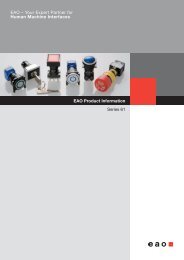
EAO – Your Expert Partner for<br />
Human Machine Interfaces<br />
EAO Product Information<br />
Series <strong>84</strong>
Switches and Indicators<br />
<strong>84</strong>
Contents<br />
<strong>84</strong><br />
Description ...................................................................................................... 3<br />
Product Assembly .......................................................................................... 4<br />
Mounting instruction ...................................................................................... 6<br />
Devices raised mounting ............................................................................... 7<br />
Devices flush mounting ................................................................................. 9<br />
<strong>Accessories</strong>................................................................................................... 13<br />
Technical Data............................................................................................... 27<br />
Application guidelines.................................................................................. 30<br />
Drawings........................................................................................................ 31<br />
Index............................................................................................................... 45<br />
2<br />
02.2009
Description<br />
<strong>84</strong><br />
<strong>General</strong> notes<br />
The Series <strong>84</strong> consists of indicators, pushbuttons and emergency-stop<br />
switches. The indicators and pushbuttons are a modular system of lens,<br />
actuator, switching element and a variety of means of connection and<br />
mounting. Different front protection of IP 67, IP 65 or IP 40 ensure that<br />
the pushbuttons are suited for industrial use.<br />
Anodized aluminium parts can have visible variations due productiontechnical<br />
reasons.<br />
Specimen order<br />
0<br />
Product Information Indicator :<br />
- Indicator actuator, IP67 <strong>84</strong>-0100.0<br />
Essential accessories :<br />
- Lens plastic blue <strong>84</strong>-7111.600<br />
- Illumination element<br />
Single-LED blue 24VDC, plug-in terminal<br />
<strong>84</strong>-8001.6620<br />
or<br />
Mounting<br />
The actuators of the Series <strong>84</strong> are inserted in a 22.5 mm diameter<br />
mounting hole and the switching units are clipped on to the rear of the<br />
actuators. The pushbutton system can be mounted as a complete unit<br />
(actuator and switching unit). Mounting from the front with the wiring<br />
already attached is also possible.<br />
When mounted on printed circuit boards the actuators are inserted in<br />
the mounting hole 22.5 mm dia. and the switching elements are fixed on<br />
the board. The printed circuit board is connected to the preassembled<br />
actuator by means of the mounting flange. There is no need for<br />
subsequent adjustment or spacing studs.<br />
Lenses<br />
The lenses are available in various colours and made either from plastic<br />
or anodized aluminium.<br />
Indicator with PCB terminal :<br />
- Indicator actuator, IP67 <strong>84</strong>-3100.1<br />
Essential accessories :<br />
- Lens plastic red <strong>84</strong>-7111.200<br />
- Illumination element with PCB terminal 92-800.042<br />
- Single-LED red 2.1VDC 10-2602.3202L<br />
- Mounting flange 92-960.0<br />
We reserve the right to modify technical data<br />
All dimensions in mm<br />
Marking<br />
The marking plates of the Series <strong>84</strong> can be marked by engraving or hot<br />
stamping.<br />
Specific symbols and markings are available on request.<br />
The lenses are without holder not engravable, since by mounting no<br />
accurate position of the engraving text is reached.<br />
Illumination<br />
To ensure full illumination, the switching elements can be supplied with<br />
integrated single LEDs in the colours red, orange, yellow, green, blue or<br />
white. The series resistor is integrated.<br />
Luminosity and wave length scattering caused by the technology used<br />
in the LED manufacturing processes may lead to visual differences in<br />
our products.<br />
Emergency-stop pushbutton, foolproof<br />
The E-stop pushbutton can be mounted in front panels with a thickness<br />
between 1 and 4 mm. It has a low behind-panel depth of 13.5 mm<br />
(max.) and 18.5 mm with plug-in terminlas and can be safely and easily<br />
adapted to PCBs of different heights. The front protection degree is<br />
IP 65.<br />
Importantly, the Series <strong>84</strong> emergency-stop requires no additional<br />
assembly because of its single-piece 'monoblock' design.<br />
The switch's status is clearly indicated by a black or green colour ring<br />
on the shaft, and the foolproof actuator design conforms to DIN EN ISO<br />
13850 and EN IEC 60947.<br />
It can be supplied with LED illumination that is visible even from the<br />
side.<br />
3<br />
02.2009
Product Assembly<br />
<strong>84</strong><br />
Indicator and pushbutton illuminative, 25 mm dia.<br />
0<br />
1<br />
2<br />
3<br />
4<br />
1 Lens<br />
2 Marking plate<br />
3 Lens holder<br />
4 Actuator housing<br />
5 Outer sealing<br />
6 Inner sealing<br />
7 Front panel<br />
8 Fixing nut<br />
9 Switching-/Illumination element with plug-in terminal (solderable)<br />
5<br />
6<br />
7<br />
8<br />
9<br />
Indicator and pushbutton illuminative, 40 mm dia.<br />
0<br />
1<br />
2<br />
3<br />
4<br />
1 Lens<br />
2 Marking plate<br />
3 Lens holder<br />
4 Actuator housing<br />
5 Sealing<br />
6 Front panel<br />
7 Fixing nut<br />
8 Switching-/Illumination element with flat ribbon cable<br />
5<br />
6<br />
7<br />
8<br />
4<br />
02.2009
Product Assembly<br />
<strong>84</strong><br />
Indicator and pushbutton illuminative, 25 mm dia., PCB version<br />
0<br />
1<br />
2<br />
3<br />
4<br />
5<br />
1 Lens<br />
2 Marking plate<br />
3 Lens holder<br />
4 Actuator housing<br />
5 Sealing<br />
6 Front panel<br />
7 Fixing nut<br />
8 Mounting flange<br />
9 Switching-/Illumination element with PCB terminal<br />
10 PCB<br />
11 Fixing screws<br />
6<br />
7<br />
8<br />
9<br />
10<br />
11<br />
Emergency-stop pushbutton<br />
0<br />
1<br />
3<br />
1 Emergency-stop pushbutton<br />
2 Fixing nut<br />
3 Position indication ring green or black<br />
2<br />
5<br />
02.2009
Mounting instruction<br />
<strong>84</strong><br />
Arrangement mounting flange for switching- and illumination element, PCB mounting<br />
0<br />
The arrangement of the mounting flanges and their number is determined by the size of<br />
the front panel or PCB. To ensure uniform, tactile switching, we recommend a layout of<br />
the flanges as per adjacent sketch.<br />
For large PCBs with several switching elements we recommend the following procedure :<br />
1. Fit the actuator to the front panel.<br />
2. Clip the mounting flange to the rear of the intended actuator.<br />
3. Screw the PCB with the components soldered to it to the assembled mounting flange.<br />
This arrangement applies to PCBs 1.6 mm thick.<br />
><br />
Dismantling mounting flange<br />
The tool <strong>84</strong>-998 must be used for removing the mounting flange from the actuator. Before<br />
removing the flange, the PCB fixing srews must be loosened.<br />
6<br />
02.2009
Devices raised mounting<br />
<strong>84</strong><br />
Emergency-stop pushbutton, foolproof EN IEC 60947-5-5, complete<br />
Application as per DIN EN ISO 13850 and EN 60204-1<br />
Continuation see next page<br />
Emergency-stop<br />
pushbutton, foolproof EN IEC<br />
60947-5-5, complete<br />
Position indication ring black<br />
Twist to unlock clockwise<br />
Position indication ring black<br />
Twist to unlock clockwise<br />
LED operating voltage: 5 ... 30 VDC<br />
Current consumption: 9.7 ...12.4 mA<br />
Position indication ring green<br />
Twist to unlock clockwise<br />
Position indication ring green<br />
Twist to unlock clockwise<br />
LED operating voltage: 5 ... 30 VDC<br />
Current consumption: 9.7 ... 12.4 mA<br />
Front protection<br />
Switching action<br />
Mushroom<br />
had cap<br />
Illumination<br />
Terminals<br />
Contacts<br />
Ø 32 mm<br />
Typ-Nr.<br />
Component layout<br />
Mounting dimensions<br />
Technical drawing<br />
IP 65 MA Plastic red without FR 1 NC <strong>84</strong>-5020.0040 2 2 16 8 0.036<br />
1 NC + 1 NO <strong>84</strong>-5030.0040 2 2 16 9 0.036<br />
2 NC <strong>84</strong>-5040.0040 2 2 16 10 0.036<br />
PT 2.8 s 1 NC <strong>84</strong>-5020.0020 1 2 16 8 0.028<br />
1 NC + 1 NO <strong>84</strong>-5030.0020 1 2 16 9 0.028<br />
2 NC <strong>84</strong>-5040.0020 1 2 16 10 0.028<br />
IP 65 MA Plastic red LED red FR 1 NC <strong>84</strong>-5021.2B40 2 2 16 11 0.036<br />
1 NC + 1 NO <strong>84</strong>-5031.2B40 2 2 16 12 0.036<br />
2 NC <strong>84</strong>-5041.2B40 2 2 16 13 0.036<br />
PT 2.8 s 1 NC <strong>84</strong>-5021.2B20 1 2 16 11 0.028<br />
1 NC + 1 NO <strong>84</strong>-5031.2B20 1 2 16 12 0.028<br />
2 NC <strong>84</strong>-5041.2B20 1 2 16 13 0.028<br />
IP 65 MA Plastic red without FR 1 NC <strong>84</strong>-5120.0040 2 2 16 8 0.036<br />
1 NC + 1 NO <strong>84</strong>-5130.0040 2 2 16 9 0.036<br />
2 NC <strong>84</strong>-5140.0040 2 2 16 10 0.036<br />
PT 2.8 s 1 NC <strong>84</strong>-5120.0020 1 2 16 8 0.028<br />
1 NC + 1 NO <strong>84</strong>-5130.0020 1 2 16 9 0.028<br />
2 NC <strong>84</strong>-5140.0020 1 2 16 10 0.028<br />
IP 65 MA Plastic red LED red FR 1 NC <strong>84</strong>-5121.2B40 2 2 16 11 0.036<br />
1 NC + 1 NO <strong>84</strong>-5131.2B40 2 2 16 12 0.036<br />
2 NC <strong>84</strong>-5141.2B40 2 2 16 13 0.036<br />
PT 2.8 s 1 NC <strong>84</strong>-5121.2B20 1 2 16 10 0.028<br />
1 NC + 1 NO <strong>84</strong>-5131.2B20 1 2 16 12 0.028<br />
2 NC <strong>84</strong>-5141.2B20 1 2 16 13 0.028<br />
Circuit drawing<br />
e<br />
Standard version:<br />
Flat ribbon-cable length 300 mm; Plug-in terminal 2.8 x 0.5 mm.<br />
Other options on request:<br />
Customisation of flat ribbon-cable and connectors.<br />
Switching action: MA = Maintained action<br />
Terminals: FR = Flat ribbon cable, PT 2.8 s = Plug-in terminal 2.8 mm (solderable)<br />
Contacts: NC = Normally closed, NO = Normally open<br />
Component layout from page 31, Mounting dimensions from page 34, Technical drawing from page 35, Circuit drawing from page 43<br />
7<br />
02.2009
Devices raised mounting<br />
<strong>84</strong><br />
Stop pushbutton grey, complete<br />
Continuation see next page<br />
Stop pushbutton grey, complete<br />
Position indication ring black<br />
Twist to unlock clockwise<br />
Position indication ring black<br />
Twist to unlock clockwise<br />
LED operating voltage: 5 ... 30 VDC<br />
Current consumption: 9.7 ...12.4 mA<br />
Front protection<br />
Switching action<br />
Mushroom<br />
had cap<br />
Illumination<br />
Terminals<br />
Contacts<br />
Ø 32 mm<br />
Typ-Nr.<br />
Component layout<br />
Mounting dimensions<br />
Technical drawing<br />
IP 65 MA Plastic grey without FR 1 NC <strong>84</strong>-6020.0040 2 2 16 8 0.036<br />
1 NC + 1 NO <strong>84</strong>-6030.0040 2 2 16 9 0.036<br />
2 NC <strong>84</strong>-6040.0040 2 2 16 10 0.036<br />
PT 2.8 s 1 NC <strong>84</strong>-6020.0020 1 2 16 8 0.028<br />
1 NC + 1 NO <strong>84</strong>-6030.0020 1 2 16 9 0.028<br />
2 NC <strong>84</strong>-6040.0020 1 2 16 10 0.028<br />
IP 65 MA Plastic grey LED red FR 1 NC <strong>84</strong>-6021.2B40 2 2 16 11 0.036<br />
1 NC + 1 NO <strong>84</strong>-6031.2B40 2 2 16 12 0.036<br />
2 NC <strong>84</strong>-6041.2B40 2 2 16 13 0.036<br />
PT 2.8 s 1 NC <strong>84</strong>-6021.2B20 1 2 16 11 0.028<br />
1 NC + 1 NO <strong>84</strong>-6031.2B20 1 2 16 12 0.028<br />
2 NC <strong>84</strong>-6041.2B20 1 2 16 13 0.028<br />
Circuit drawing<br />
e<br />
Standard version:<br />
Flat ribbon-cable length 300 mm; Plug-in terminal 2.8 x 0.5 mm.<br />
Other options on request:<br />
Customisation of flat ribbon-cable and connectors.<br />
Switching action: MA = Maintained action<br />
Terminals: FR = Flat ribbon cable, PT 2.8 s = Plug-in terminal 2.8 mm (solderable)<br />
Contacts: NC = Normally closed, NO = Normally open<br />
Component layout from page 31, Mounting dimensions from page 34, Technical drawing from page 35, Circuit drawing from page 43<br />
8<br />
02.2009
Devices flush mounting<br />
<strong>84</strong><br />
Indicator actuator<br />
Illuminated lens, non-illuminated bezel<br />
Essential <strong>Accessories</strong>:<br />
d Illumination element page 17<br />
d Lens plastic page 13<br />
Continuation see next page<br />
Front protection<br />
Mounting dimensions<br />
Technical drawing<br />
Front ring<br />
Ø 25 mm<br />
Typ-Nr.<br />
e<br />
Indicator actuator IP 40 Plastic black <strong>84</strong>-3100.0 1 15 0.004<br />
IP 67 Aluminium natural <strong>84</strong>-0200.7 1 15 0.008<br />
Plastic black <strong>84</strong>-0100.0 1 15 0.003<br />
Mounting dimensions from page 34, Technical drawing from page 35<br />
Illuminated pushbutton actuator<br />
Illuminated lens, non-illuminated bezel<br />
Essential <strong>Accessories</strong>:<br />
d Lens plastic page 13<br />
d Switching element illuminated page 19<br />
Continuation see next page<br />
Switching action<br />
Front protection<br />
Front ring<br />
Ø 40 mm<br />
Typ-Nr.<br />
Ø 25 mm<br />
Typ-Nr.<br />
Mounting dimensions<br />
Technical drawing<br />
Circuit drawing<br />
Illuminated pushbutton actuator M IP 67 Aluminium natural <strong>84</strong>-1221.7 3 17 4 0.022<br />
IP 40 Plastic black <strong>84</strong>-2101.0 1 15 4 0.004<br />
IP 67 Aluminium black <strong>84</strong>-1201.0 1 15 4 0.008<br />
Aluminium blue <strong>84</strong>-1201.6 1 15 4 0.008<br />
Aluminium green <strong>84</strong>-1201.5 1 15 4 0.008<br />
Aluminium natural <strong>84</strong>-1201.7 1 15 4 0.008<br />
Aluminium red <strong>84</strong>-1201.2 1 15 4 0.008<br />
Aluminium yellow <strong>84</strong>-1201.4 1 15 4 0.008<br />
Plastic black <strong>84</strong>-1101.0 1 15 4 0.003<br />
e<br />
Switching action: M = Momentary action<br />
Mounting dimensions from page 34, Technical drawing from page 35, Circuit drawing from page 43<br />
9<br />
02.2009
Devices flush mounting<br />
<strong>84</strong><br />
Pushbutton actuator<br />
Non-illuminated lens and bezel<br />
Essential <strong>Accessories</strong>:<br />
d Lens metal page 14<br />
d Switching element non-illuminated page 20<br />
Continuation see next page<br />
Front protection<br />
Switching action<br />
Front ring<br />
Ø 40 mm<br />
Typ-Nr.<br />
Ø 25 mm<br />
Typ-Nr.<br />
Mounting dimensions<br />
Technical drawing<br />
Circuit drawing<br />
Pushbutton actuator IP 67 M Aluminium natural <strong>84</strong>-1221.7 3 17 4 0.022<br />
IP 40 M Plastic black <strong>84</strong>-2101.0 1 15 4 0.004<br />
IP 67 M Aluminium black <strong>84</strong>-1201.0 1 15 4 0.008<br />
Aluminium blue <strong>84</strong>-1201.6 1 15 4 0.008<br />
Aluminium green <strong>84</strong>-1201.5 1 15 4 0.008<br />
Aluminium natural <strong>84</strong>-1201.7 1 15 4 0.008<br />
Aluminium red <strong>84</strong>-1201.2 1 15 4 0.008<br />
Aluminium yellow <strong>84</strong>-1201.4 1 15 4 0.008<br />
Plastic black <strong>84</strong>-1101.0 1 15 4 0.003<br />
e<br />
Switching action: M = Momentary action<br />
Mounting dimensions from page 34, Technical drawing from page 35, Circuit drawing from page 43<br />
Indicator actuator with ring illumination (illuminated bezel)<br />
Essential <strong>Accessories</strong>:<br />
d Illumination element page 17<br />
d Lens metal for Ring illumination page 14<br />
Continuation see next page<br />
Ø 25 mm<br />
Front ring<br />
Typ-Nr.<br />
e<br />
Indicator actuator with ring illumination (illuminated bezel) IP 67 Plastic translucent <strong>84</strong>-0090.7 1 15 0.006<br />
Front protection<br />
Mounting dimensions<br />
Technical drawing<br />
<strong>Accessories</strong> for ring illumination:<br />
Essential lenses Typ-Nr. <strong>84</strong>-7202.x00A and <strong>84</strong>-7205.x00A<br />
Bi-colour illumination elements are not recommended.<br />
Mounting dimensions from page 34, Technical drawing from page 35<br />
10<br />
02.2009
Devices flush mounting<br />
<strong>84</strong><br />
Pushbutton actuator with ring illumination (illuminated bezel)<br />
Essential <strong>Accessories</strong>:<br />
d Lens metal for Ring illumination page 14<br />
d Switching element illuminated page 19<br />
Continuation see next page<br />
Ø 25 mm<br />
Front ring<br />
Typ-Nr.<br />
e<br />
Pushbutton actuator with ring illumination (illuminated bezel) M IP 67 Plastic translucent <strong>84</strong>-1091.7 1 15 4 0.006<br />
Switching action<br />
Front protection<br />
Mounting dimensions<br />
Technical drawing<br />
Circuit drawing<br />
<strong>Accessories</strong> for ring illumination:<br />
Essential lenses Typ-Nr. <strong>84</strong>-7202.x00A and <strong>84</strong>-7205.x00A<br />
Bi-colour switching elements are not recommended.<br />
Switching action: M = Momentary action<br />
Mounting dimensions from page 34, Technical drawing from page 35, Circuit drawing from page 43<br />
Indicator actuator with ring illumination (illuminated multi-colour bezel)<br />
Essential <strong>Accessories</strong>:<br />
d IIlumination element PCB mounting page 21<br />
d Lens plastic page 13<br />
d Mounting flange page 21<br />
d Single-LED page 22<br />
Continuation see next page<br />
Ø 25 mm<br />
Front ring<br />
Typ-Nr.<br />
e<br />
Indicator actuator with ring illumination (illuminated multi-colour bezel) IP 67 Plastic transparent <strong>84</strong>-0080.7 1 15 0.006<br />
Front protection<br />
Mounting dimensions<br />
Technical drawing<br />
Mounting dimensions from page 34, Technical drawing from page 35<br />
11<br />
02.2009
Devices flush mounting<br />
<strong>84</strong><br />
Pushbutton actuator with ring illumination (illuminated multi-colour bezel)<br />
Essential <strong>Accessories</strong>:<br />
d Lens plastic page 13<br />
d Mounting flange page 21<br />
d Single-LED page 22<br />
d Switching element PCB mounting illuminative page 21<br />
Continuation see next page<br />
Pushbutton actuator with ring illumination<br />
(illuminated multi-colour bezel)<br />
Switching action<br />
Front protection<br />
Mounting dimensions<br />
Technical drawing<br />
Circuit drawing<br />
Ø 25 mm<br />
Front ring<br />
Typ-Nr.<br />
e<br />
M IP 67 Plastic transparent <strong>84</strong>-1081.7 1 15 4 0.006<br />
Switching action: M = Momentary action<br />
Mounting dimensions from page 34, Technical drawing from page 35, Circuit drawing from page 43<br />
12<br />
02.2009
<strong>Accessories</strong><br />
<strong>84</strong><br />
Front<br />
Lens plastic<br />
Continuation see next page<br />
Lens plastic<br />
flush - level, illuminative<br />
Mounting type<br />
Lens<br />
Ø 25 mm<br />
Typ-Nr. e<br />
level with bezel blue transparent <strong>84</strong>-7111.600 0.001<br />
colourless transparent <strong>84</strong>-7111.700 0.001<br />
green transparent <strong>84</strong>-7111.500 0.001<br />
orange transparent <strong>84</strong>-7111.300 0.001<br />
red transparent <strong>84</strong>-7111.200 0.001<br />
yellow transparent <strong>84</strong>-7111.400 0.001<br />
flush - level, non-illuminative level with bezel black opaque <strong>84</strong>-7121.000 0.001<br />
level with bezel grey opaque <strong>84</strong>-7121.800 0.001<br />
flush - raised, illuminative raised above bezel blue transparent <strong>84</strong>-7115.600 0.001<br />
colourless transparent <strong>84</strong>-7115.700 0.001<br />
green transparent <strong>84</strong>-7115.500 0.001<br />
orange transparent <strong>84</strong>-7115.300 0.001<br />
red transparent <strong>84</strong>-7115.200 0.001<br />
yellow transparent <strong>84</strong>-7115.400 0.001<br />
flush - raised, non-illuminative raised above bezel black opaque <strong>84</strong>-7125.000 0.001<br />
grey opaque <strong>84</strong>-7125.800 0.001<br />
Marking plate for lens plastic<br />
can be hot stamped<br />
Continuation see next page<br />
Marking plate Typ-Nr. e<br />
Marking plate for lens plastic Plastic colourless transparent 61-9707.7 0.001<br />
Lens plastic with symbol<br />
Continuation see next page<br />
Lens plastic with symbol<br />
flush - level, illuminative<br />
Mounting type Symbol Lens<br />
Ø 25 mm<br />
Typ-Nr. e<br />
level with bezel ON/OFF blue transparent <strong>84</strong>-7111.602 0.002<br />
colourless transparent <strong>84</strong>-7111.702 0.002<br />
green transparent <strong>84</strong>-7111.502 0.002<br />
red transparent <strong>84</strong>-7111.202 0.002<br />
Ring blue transparent <strong>84</strong>-7111.601 0.002<br />
colourless transparent <strong>84</strong>-7111.701 0.002<br />
green transparent <strong>84</strong>-7111.501 0.002<br />
orange transparent <strong>84</strong>-7111.301 0.002<br />
red transparent <strong>84</strong>-7111.201 0.002<br />
yellow transparent <strong>84</strong>-7111.401 0.002<br />
Stand by blue transparent <strong>84</strong>-7111.603 0.002<br />
colourless transparent <strong>84</strong>-7111.703 0.002<br />
green transparent <strong>84</strong>-7111.503 0.002<br />
red transparent <strong>84</strong>-7111.203 0.002<br />
The silvery coat is being applied on the lens (screen print) with an additional protective lacquer.<br />
13<br />
02.2009
<strong>Accessories</strong><br />
<strong>84</strong><br />
Lens metal<br />
Continuation see next page<br />
Lens metal<br />
convex - level, non-illuminative<br />
Mounting type<br />
Lens<br />
Ø 25 mm<br />
Typ-Nr. e<br />
level with bezel Aluminium black <strong>84</strong>-7202.000 0.003<br />
Aluminium blue <strong>84</strong>-7202.600 0.003<br />
Aluminium green <strong>84</strong>-7202.500 0.003<br />
Aluminium natural <strong>84</strong>-7202.800 0.003<br />
Aluminium red <strong>84</strong>-7202.200 0.003<br />
Aluminium yellow <strong>84</strong>-7202.400 0.003<br />
flush - level, non-illuminative level with bezel Aluminium black <strong>84</strong>-7201.000 0.003<br />
Aluminium blue <strong>84</strong>-7201.600 0.003<br />
Aluminium green <strong>84</strong>-7201.500 0.003<br />
Aluminium natural <strong>84</strong>-7201.800 0.003<br />
Aluminium red <strong>84</strong>-7201.200 0.003<br />
Aluminium yellow <strong>84</strong>-7201.400 0.003<br />
flush - raised, non-illuminative raised above bezel Aluminium black <strong>84</strong>-7205.000 0.003<br />
Aluminium blue <strong>84</strong>-7205.600 0.003<br />
Aluminium green <strong>84</strong>-7205.500 0.003<br />
Aluminium natural <strong>84</strong>-7205.800 0.003<br />
Aluminium red <strong>84</strong>-7205.200 0.003<br />
Aluminium yellow <strong>84</strong>-7205.400 0.003<br />
Lens metal for Ring illumination<br />
Continuation see next page<br />
Lens metal for Ring illumination<br />
convex - raised, non-illuminative<br />
Mounting type<br />
Lens<br />
Ø 25 mm<br />
Typ-Nr. e<br />
raised above bezel Aluminium black <strong>84</strong>-7202.000A 0.004<br />
Aluminium blue <strong>84</strong>-7202.600A 0.004<br />
Aluminium green <strong>84</strong>-7202.500B 0.004<br />
Aluminium natural <strong>84</strong>-7202.800A 0.004<br />
Aluminium red <strong>84</strong>-7202.200A 0.004<br />
Aluminium yellow <strong>84</strong>-7202.400A 0.004<br />
flush - raised, non-illuminative raised above bezel Aluminium black <strong>84</strong>-7205.000A 0.003<br />
Aluminium blue <strong>84</strong>-7205.600A 0.003<br />
Aluminium green <strong>84</strong>-7205.500A 0.003<br />
Aluminium natural <strong>84</strong>-7205.800A 0.003<br />
Aluminium red <strong>84</strong>-7205.200A 0.003<br />
Aluminium yellow <strong>84</strong>-7205.400A 0.003<br />
14<br />
02.2009
<strong>Accessories</strong><br />
<strong>84</strong><br />
Lens metal with spot<br />
Continuation see next page<br />
Lens metal with spot<br />
flush - level, illuminative<br />
Mounting type<br />
Lens<br />
Ø 25 mm<br />
Typ-Nr. e<br />
level with bezel Aluminium black <strong>84</strong>-7211.000 0.002<br />
Aluminium blue <strong>84</strong>-7211.600 0.002<br />
Aluminium green <strong>84</strong>-7211.500 0.002<br />
Aluminium natural <strong>84</strong>-7211.800 0.002<br />
Aluminium red <strong>84</strong>-7211.200 0.002<br />
Aluminium yellow <strong>84</strong>-7211.400 0.002<br />
flush - raised, illuminative raised above bezel Aluminium black <strong>84</strong>-7215.000 0.002<br />
Aluminium blue <strong>84</strong>-7215.600 0.002<br />
Aluminium green <strong>84</strong>-7215.500 0.002<br />
Aluminium natural <strong>84</strong>-7215.800 0.002<br />
Aluminium red <strong>84</strong>-7215.200 0.002<br />
Aluminium yellow <strong>84</strong>-7215.400 0.002<br />
Mushroom-head cap<br />
Continuation see next page<br />
Mushroom had cap<br />
Ø 32 mm<br />
Typ-Nr. e<br />
Mushroom-head cap Plastic black opaque <strong>84</strong>-7124.000A 0.004<br />
Plastic blue opaque <strong>84</strong>-7124.600A 0.004<br />
Plastic blue transparent <strong>84</strong>-7114.600A 0.004<br />
Plastic green opaque <strong>84</strong>-7124.500A 0.004<br />
Plastic red opaque <strong>84</strong>-7124.200A 0.004<br />
Plastic yellow opaque <strong>84</strong>-7124.400A 0.004<br />
Front protective cap<br />
for flush - level lenses only<br />
Continuation see next page<br />
Front protective cap Typ-Nr. e<br />
Front protective cap Silicone natural transparent <strong>84</strong>-9103.7 0.001<br />
ATTENTION<br />
when using the front protection cover the external sealing in the actuator has to be removed !<br />
Legend frame<br />
for devices 25 mm dia.<br />
Continuation see next page<br />
Legend frame<br />
30 x 50 mm, adhesive, Aluminium black<br />
Technical drawing<br />
Typ-Nr. e<br />
61-9980.0 7 0.001<br />
Technical drawing from page 35<br />
15<br />
02.2009
<strong>Accessories</strong><br />
<strong>84</strong><br />
Legend plate insert<br />
for Legend frame 61-9980.0<br />
Continuation see next page<br />
Legend plate insert<br />
14.5 x 23.5 mm, adhesive, Aluminium black<br />
Typ-Nr. e<br />
704.968.1 0.001<br />
14.5 x 23.5 mm, adhesive, Aluminium natural 704.968.0 0.001<br />
Blind plug<br />
Continuation see next page<br />
Blind plug<br />
Size 25 mm dia., for mounting hole 22.5 mm dia.<br />
Technical drawing from page 35<br />
Technical drawing<br />
Blind plug<br />
Typ-Nr. e<br />
Plastic black 61-9453.0 8 0.006<br />
Size 36 mm dia., for mounting hole 30.5 mm dia. Plastic black 704.964.8 1 0.007<br />
16<br />
02.2009
<strong>Accessories</strong><br />
<strong>84</strong><br />
><br />
Backside<br />
Illumination element<br />
Continuation see next page<br />
Illumination element<br />
LED and built-in resistor<br />
included<br />
Protection degree<br />
Illumination<br />
Operating voltage/-<br />
current<br />
Typ-Nr.<br />
e<br />
IP 40 Single-LED blue 12 VDC, 10 mA FR <strong>84</strong>-8001.6340 5 0.010<br />
PT 2.8 s <strong>84</strong>-8001.6320 5 0.005<br />
24 VDC, 20 mA FR <strong>84</strong>-8001.6640 5 0.010<br />
PT 2.8 s <strong>84</strong>-8001.6620 5 0.005<br />
Single-LED green 12 VDC, 10 mA FR <strong>84</strong>-8001.5340 5 0.010<br />
PT 2.8 s <strong>84</strong>-8001.5320 5 0.005<br />
24 VDC, 20 mA FR <strong>84</strong>-8001.5640 5 0.010<br />
PT 2.8 s <strong>84</strong>-8001.5620 5 0.005<br />
Single-LED orange 12 VDC, 10 mA FR <strong>84</strong>-8001.3340 5 0.010<br />
PT 2.8 s <strong>84</strong>-8001.3320 5 0.005<br />
24 VDC, 20 mA FR <strong>84</strong>-8001.3640 5 0.010<br />
PT 2.8 s <strong>84</strong>-8001.3620 5 0.005<br />
Single-LED red 12 VDC, 10 mA FR <strong>84</strong>-8001.2340 5 0.010<br />
12 VDC, 20 mA PT 2.8 s <strong>84</strong>-8001.2320 5 0.005<br />
24 VDC, 20 mA FR <strong>84</strong>-8001.2640 5 0.010<br />
PT 2.8 s <strong>84</strong>-8001.2620 5 0.005<br />
Single-LED white 12 VDC, 10 mA FR <strong>84</strong>-8001.9340 5 0.010<br />
PT 2.8 s <strong>84</strong>-8001.9320 5 0.005<br />
24 VDC, 20 mA FR <strong>84</strong>-8001.9640 5 0.010<br />
PT 2.8 s <strong>84</strong>-8001.9620 5 0.005<br />
Single-LED yellow 12 VDC, 10 mA FR <strong>84</strong>-8001.4340 5 0.010<br />
PT 2.8 s <strong>84</strong>-8001.4320 5 0.005<br />
24 VDC, 20 mA FR <strong>84</strong>-8001.4640 5 0.010<br />
PT 2.8 s <strong>84</strong>-8001.4620 5 0.005<br />
Terminals<br />
Circuit drawing<br />
Standard version:<br />
Cable length 300 mm with insulated ferrule; Plug-in terminal 2.8 x 0.8 mm.<br />
Other options on request:<br />
Customisation of cable and connectors; Rear side fully sealed (IP 67).<br />
Protection degree (rear side):<br />
IP 40, upgrade to IP 67 with plug typ-Nr. <strong>84</strong>-900 possible; With applications where strong vibrations occure, the plugs may<br />
become loose.<br />
Terminals: FR = Flat ribbon cable, PT 2.8 s = Plug-in terminal 2.8 mm (solderable)<br />
Circuit drawing from page 43<br />
17<br />
02.2009
<strong>Accessories</strong><br />
<strong>84</strong><br />
Illumination element with Bi-colour illumination<br />
Continuation see next page<br />
Illumination element with<br />
Bi-colour illumination<br />
LED and built-in resistor included<br />
Illumination<br />
Bi-colour LED<br />
red/green<br />
Bi-colour LED<br />
yellow/green<br />
Protection degree<br />
Terminals<br />
Operating voltage/-<br />
current<br />
Typ-Nr.<br />
e<br />
24 VDC, 20 mA IP 40 PT 2.8 s <strong>84</strong>-8005.8620 1 0.005<br />
IP 67 FR <strong>84</strong>-8005.8640 2 0.011<br />
24 VDC, 20 mA IP 40 PT 2.8 s <strong>84</strong>-8005.7620 1 0.005<br />
IP 67 FR <strong>84</strong>-8005.7640 2 0.011<br />
Circuit drawing<br />
Standard version:<br />
Cable length 300 mm with insulated ferrule; Plug-in terminal 2.8 x 0.8 mm.<br />
Other options on request:<br />
Customisation of cable and connectors; Rear side fully sealed (IP 67).<br />
Best illumination level will be reached with Alu lens with window, Typ-Nr. <strong>84</strong>-7215.x00 and <strong>84</strong>-7211.x00.<br />
Protection degree (rear side):<br />
- Plug-in terminal IP 40, upgrade to IP 67 with plug typ-Nr. <strong>84</strong>-900 possible. With applications where strong vibrations<br />
occure, the plugs may become loose.<br />
- Cabel connection IP 67, rear side fully sealed. The illumination element of the cable version cannot be disconnected from<br />
the actuator any longer.<br />
Terminals: PT 2.8 s = Plug-in terminal 2.8 mm (solderable), FR = Flat ribbon cable<br />
Circuit drawing from page 43<br />
18<br />
02.2009
<strong>Accessories</strong><br />
<strong>84</strong><br />
Switching element illuminated<br />
Continuation see next page<br />
Switching element<br />
illuminated<br />
LED and built-in<br />
resistor included<br />
Protection degree<br />
Contacts<br />
Illumination<br />
Operating voltage/-<br />
current<br />
Typ-Nr.<br />
e<br />
IP 40 1 NO Single-LED blue 12 VDC, 10 mA FR <strong>84</strong>-8511.6340 7 0.015<br />
12 VDC, 20 mA PT 2.8 s <strong>84</strong>-8511.6320 7 0.006<br />
24 VDC, 20 mA FR <strong>84</strong>-8511.6640 7 0.015<br />
PT 2.8 s <strong>84</strong>-8511.6620 7 0.006<br />
Single-LED green 12 VDC, 10 mA FR <strong>84</strong>-8511.5340 7 0.015<br />
PT 2.8 s <strong>84</strong>-8511.5320 7 0.006<br />
24 VDC, 20 mA FR <strong>84</strong>-8511.5640 7 0.015<br />
PT 2.8 s <strong>84</strong>-8511.5620 7 0.006<br />
Single-LED orange 12 VDC, 10 mA FR <strong>84</strong>-8511.3340 7 0.015<br />
PT 2.8 s <strong>84</strong>-8511.3320 7 0.006<br />
24 VDC, 20 mA FR <strong>84</strong>-8511.3640 7 0.015<br />
PT 2.8 s <strong>84</strong>-8511.3620 7 0.006<br />
Single-LED red 12 VDC, 10 mA FR <strong>84</strong>-8511.2340 7 0.015<br />
PT 2.8 s <strong>84</strong>-8511.2320 7 0.006<br />
24 VDC, 20 mA FR <strong>84</strong>-8511.2640 7 0.015<br />
PT 2.8 s <strong>84</strong>-8511.2620 7 0.006<br />
Single-LED white 12 VDC, 10 mA FR <strong>84</strong>-8511.9340 7 0.015<br />
PT 2.8 s <strong>84</strong>-8511.9320 7 0.006<br />
24 VDC, 20 mA FR <strong>84</strong>-8511.9640 7 0.015<br />
PT 2.8 s <strong>84</strong>-8511.9620 7 0.006<br />
Single-LED yellow 12 VDC, 10 mA FR <strong>84</strong>-8511.4340 7 0.015<br />
PT 2.8 s <strong>84</strong>-8511.4320 7 0.006<br />
24 VDC, 20 mA FR <strong>84</strong>-8511.4640 7 0.015<br />
PT 2.8 s <strong>84</strong>-8511.4620 7 0.006<br />
Terminals<br />
Circuit drawing<br />
Standard version:<br />
Cable length 300 mm with insulated ferrule; Plug-in terminal 2.8 x 0.8 mm.<br />
Other options on request:<br />
Customisation of cable and connectors; Rear side fully sealed (IP 67).<br />
Protection degree (rear side):<br />
IP 40, upgrade to IP 67 with plug typ-Nr. <strong>84</strong>-900 possible; With applications where strong vibrations occure, the plugs may<br />
become loose.<br />
Contacts: NO = Normally open<br />
Terminals: FR = Flat ribbon cable, PT 2.8 s = Plug-in terminal 2.8 mm (solderable)<br />
Circuit drawing from page 43<br />
19<br />
02.2009
<strong>Accessories</strong><br />
<strong>84</strong><br />
Switching element with Bi-colour illumination<br />
Continuation see next page<br />
Switching element with<br />
Bi-colour illumination<br />
LED and built-in resistor<br />
included<br />
Protection degree<br />
Contacts<br />
Illumination<br />
IP 67 1 NO Bi-colour LED<br />
red/green<br />
Bi-colour LED<br />
yellow/green<br />
Terminals<br />
Circuit drawing<br />
Operating voltage/-<br />
current<br />
Typ-Nr.<br />
e<br />
24 VDC, 20 mA FR <strong>84</strong>-8515.8640 3 0.015<br />
24 VDC, 20 mA FR <strong>84</strong>-8515.7640 3 0.015<br />
Standard version:<br />
Cable length 300 mm with insulated ferrule.<br />
Other options on request:<br />
Customisation of cable and connectors.<br />
Protection degree IP 67, rear side fully sealed. The switching element cannot be disconnected from the actuator any<br />
longer.<br />
Best illumination level will be reached with Alu lens with window, Typ-Nr. <strong>84</strong>-7215.x00 and <strong>84</strong>-7211.x00.<br />
Contacts: NO = Normally open<br />
Terminals: FR = Flat ribbon cable<br />
Circuit drawing from page 43<br />
Switching element non-illuminated<br />
Continuation see next page<br />
Typ-Nr.<br />
e<br />
Switching element non-illuminated IP 40 1 NO FR <strong>84</strong>-8510.0040 6 0.010<br />
PT 2.8 s <strong>84</strong>-8510.0020 6 0.005<br />
Protection degree<br />
Contacts<br />
Terminals<br />
Circuit drawing<br />
Standard version:<br />
Cable length 300 mm with insulated ferrule; Plug-in terminal 2.8 x 0.8 mm (solderable).<br />
Other options on request:<br />
Customisation of cable and connectors; Rear side fully sealed (IP 67).<br />
Protection degree (rear side):<br />
IP 40, upgrade to IP 67 with plug typ-Nr. <strong>84</strong>-900 possible; With applications where strong vibrations occure, the plugs may<br />
become loose.<br />
Contacts: NO = Normally open<br />
Terminals: FR = Flat ribbon cable, PT 2.8 s = Plug-in terminal 2.8 mm (solderable)<br />
Circuit drawing from page 43<br />
20<br />
02.2009
<strong>Accessories</strong><br />
<strong>84</strong><br />
Switching element PCB mounting illuminative<br />
The customer has to decide what series resistor shall be used to the LED<br />
Continuation see next page<br />
Contacts<br />
Terminals<br />
Typ-Nr.<br />
e<br />
Switching element PCB mounting illuminative 1 NO P 92-851.342 4 14 14 0.001<br />
Component layout<br />
Technical drawing<br />
Circuit drawing<br />
Illumination and mounting flange to be ordered separately.<br />
Contacts: NO = Normally open<br />
Terminals: P = PCB terminal<br />
Component layout from page 31, Technical drawing from page 35, Circuit drawing from page 43<br />
IIlumination element PCB mounting<br />
The customer has to decide what series resistor shall be used to the LED<br />
Continuation see next page<br />
Typ-Nr.<br />
e<br />
IIlumination element PCB mounting P 92-800.042 3 9 0.001<br />
Terminals<br />
Component layout<br />
Technical drawing<br />
Illumination and mounting flange to be ordered separately.<br />
Terminals: P = PCB terminal<br />
Component layout from page 31, Technical drawing from page 35<br />
Mounting flange<br />
Continuation see next page<br />
Mounting flange<br />
Ring illumination (illuminated multi-color bezel)<br />
Technical drawing from page 35<br />
Technical drawing<br />
Typ-Nr. e<br />
<strong>84</strong>-960.0 13 0.001<br />
Standard version (non-illuminated) 92-960.0 10 0.001<br />
Flat receptacle<br />
Continuation see next page<br />
Flat receptacle<br />
2.8 x 0.8 mm<br />
Typ-Nr. e<br />
<strong>84</strong>-9420 0.001<br />
21<br />
02.2009
<strong>Accessories</strong><br />
<strong>84</strong><br />
Insulation sleeve<br />
Continuation see next page<br />
Insulation sleeve<br />
for Flat receptacles <strong>84</strong>-9420<br />
Typ-Nr. e<br />
31-929 0.001<br />
Plug<br />
Continuation see next page<br />
Typ-Nr. e<br />
Plug <strong>84</strong>-900 0.001<br />
for back protection IP67 of switching elements and illumination elements.<br />
Two plugs are nessecary per element.<br />
><br />
Illumination<br />
Single-LED<br />
The customer has to decide what series resistor shall be used to the LED<br />
Continuation see next page<br />
Socket Light colour Operating voltage/-current Typ-Nr. e<br />
Single-LED T1 Bi-Pin blue 3.5 VDC, 20 mA 10-2602.3206L 0.001<br />
green 3.5 VDC, 20 mA 10-2602.3205L 0.001<br />
orange 2.1 VDC, 20 mA 10-2602.3203L 0.001<br />
red 2.1 VDC, 20 mA 10-2602.3202L 0.001<br />
white 3.5 VDC, 20 mA 10-2602.3209L 0.001<br />
yellow 2.2 VDC, 20 mA 10-2602.3174D 0.001<br />
Bi-colour LED<br />
The customer has to decide what series resistor shall be used to the LED<br />
Continuation see next page<br />
Socket Light colour Operating voltage/-current Typ-Nr. e<br />
Bi-colour LED T1 Bi-Pin red/green 1.9/3.5 VDC, 20 mA 10-2603.320AL 0.001<br />
yellow/green 2.0/3.2 VDC, 20 mA 10-2603.320CL 0.001<br />
Multi-LED<br />
The customer has to decide what series resistor shall be used to the LED<br />
Continuation see next page<br />
Socket Light colour Operating voltage/-current Typ-Nr. e<br />
Multi-LED T1 Bi-Pin yellow 12 VDC, 40 mA 10-5609.3174D 0.001<br />
22<br />
02.2009
<strong>Accessories</strong><br />
<strong>84</strong><br />
><br />
Emergency-stop and Stop pushbutton<br />
Emergency-stop label<br />
front panel thickness 3 mm max.<br />
Continuation see next page<br />
Emergency-stop label<br />
60 mm dia., yellow, Mounting hole size 22.5 mm dia.<br />
Marking Typ-Nr. e<br />
ARRET D'URGENCE 704.963.7 0.011<br />
EMERGENCY STOP 704.963.6 0.011<br />
NOT AUS 704.963.5 0.011<br />
NOT HALT 704.963.8 0.011<br />
90 mm dia., yellow, Mounting hole size 22.5 mm dia. ARRET D'URGENCE 704.963.2 0.011<br />
EMERGENCY STOP 704.963.1 0.011<br />
NOT AUS 704.963.0 0.011<br />
NOT HALT 704.963.3 0.011<br />
Emergency-stop protective shroud<br />
Front panel thickness 1 ... 3 mm<br />
Continuation see next page<br />
Emergency-stop protective shroud<br />
45 mm dia., IP 40, mounting hole 22.5 mm dia., with anti-twist device<br />
Marking<br />
Typ-Nr. e<br />
without <strong>84</strong>-909 12 0.021<br />
50 mm dia., IP 65, mounting hole 22.5 mm dia., with anti-twist device EMERGENCY STOP <strong>84</strong>-902B 0.006<br />
NOT - AUS <strong>84</strong>-902A 0.006<br />
NOT - HALT <strong>84</strong>-902D 0.006<br />
without <strong>84</strong>-902 0.006<br />
Please note: By using the protective shroud Typ-Nr. <strong>84</strong>-909 the E-stop or Stop-Switch has to be mounted twisted by<br />
180 °. Consult the dimensional drawing therfore.<br />
Technical drawing from page 35<br />
Technical drawing<br />
Fixing nut<br />
Continuation see next page<br />
Fixing nut<br />
28 mm dia., for limited-space applications<br />
Fixing nut Typ-Nr. e<br />
Plastic black <strong>84</strong>-905 0.002<br />
30 mm dia., standard delivery Plastic black <strong>84</strong>-908 0.002<br />
23<br />
02.2009
<strong>Accessories</strong><br />
<strong>84</strong><br />
Emergency-stop enclosures<br />
Bottom grey similar RAL 7035; cover lead-sealable, yellow similar RAL 1004<br />
Continuation see next page<br />
Emergency-stop enclosures<br />
with mounting hole 22.5 mm dia., with anti- twist device<br />
Technical drawing<br />
Dimension<br />
Typ-Nr. e<br />
L 65 mm, W 65 mm, H 57 mm <strong>84</strong>-910 11 0.099<br />
Openings for cable gland M16 or M20.<br />
Protection class IP 66.<br />
Technical drawing from page 35<br />
Stop pushbutton enclosure<br />
Grey similar RAL 7035; cover lead-sealable<br />
Continuation see next page<br />
Stop pushbutton enclosure<br />
with mounting hole 1 x 22.5 mm dia., with anti-twist device<br />
Technical drawing from page 35<br />
Technical drawing<br />
Dimension<br />
Typ-Nr. e<br />
L 94 mm, W 94 mm, H 81 mm 704.945.1 2 0.211<br />
with mounting hole 2 x 22.5 mm dia., with anti-twist device L 130 mm, W 94 mm, H 81 mm 704.945.2 3 0.251<br />
with mounting hole 3 x 22.5 mm dia., with anti-twist device L 180 mm, W 94 mm, H 81 mm 704.945.3 4 0.313<br />
with mounting hole 4 x 22.5 mm dia., with anti-twist device L 180 mm, W 182 mm, H 110 mm 704.945.4 5 0.572<br />
with mounting hole 6 x 22.5 mm dia., with anti-twist device L 180 mm, W 182 mm, H 110 mm 704.945.5 6 0.568<br />
Cable gland<br />
Continuation see next page<br />
Cable gland<br />
M16, Plastic grey<br />
with traction relief; protection degree IP 68.<br />
Typ-Nr. e<br />
61-9481.6 0.007<br />
M20, Plastic grey 704.945.6 0.011<br />
Flat receptacle<br />
Continuation see next page<br />
Flat receptacle<br />
2.8 x 0.5 mm for Plug-in terminal<br />
Typ-Nr. e<br />
31-946 0.001<br />
24<br />
02.2009
<strong>Accessories</strong><br />
<strong>84</strong><br />
Insulation sleeve<br />
Continuation see next page<br />
Insulation sleeve<br />
for Flat receptacles 31-946<br />
Typ-Nr. e<br />
31-929 0.001<br />
><br />
Stop request pushbutton<br />
Housing, pole mounting 35 mm dia.<br />
Continuation see next page<br />
Housing Colour Typ-Nr. e<br />
Housing, pole mounting 35 mm dia. Plastic blue RAL 5017 traffic blue <strong>84</strong>-9500.6A 18 0.035<br />
Plastic grey RAL 7016 <strong>84</strong>-9500.8 18 0.035<br />
Plastic yellow RAL 1023 <strong>84</strong>-9500.4 18 0.035<br />
Screws are not contained in the scope of supply.<br />
Technical drawing from page 35<br />
Technical drawing<br />
Housing, pole mounting 38 mm dia.<br />
Continuation see next page<br />
Housing Colour Typ-Nr. e<br />
Housing, pole mounting 38 mm dia. Plastic grey RAL 7016 <strong>84</strong>-9600.8 19 0.030<br />
Plastic yellow RAL 1023 <strong>84</strong>-9600.4 19 0.030<br />
Screws are not contained in the scope of supply.<br />
Technical drawing from page 35<br />
Technical drawing<br />
Adaptor, reducing to 30 mm dia.<br />
Continuation see next page<br />
Adaptor, reducing to 30 mm dia.<br />
for housing, pole mounting 35 mm dia.<br />
Housing Colour Typ-Nr. e<br />
Plastic grey RAL 7016 <strong>84</strong>-9700.8 22 0.024<br />
Plastic yellow RAL 1023 <strong>84</strong>-9700.4 22 0.024<br />
Technical drawing<br />
Technical drawing from page 35<br />
25<br />
02.2009
<strong>Accessories</strong><br />
<strong>84</strong><br />
Adaptor, reducing to 25 mm dia.<br />
Continuation see next page<br />
Adaptor, reducing to 25 mm dia.<br />
for housing, pole mounting 35 mm dia.<br />
Housing Colour Typ-Nr. e<br />
Plastic grey RAL 7016 <strong>84</strong>-9300.8 21 0.008<br />
Plastic yellow RAL 1023 <strong>84</strong>-9300.4 21 0.008<br />
Technical drawing<br />
Technical drawing from page 35<br />
Housing, wall mounting<br />
Continuation see next page<br />
Housing Colour Typ-Nr. e<br />
Housing, wall mounting Plastic grey RAL 7016 <strong>84</strong>-9800.8 20 0.024<br />
Plastic yellow RAL 1023 <strong>84</strong>-9800.4 20 0.024<br />
Screws are not contained in the scope of supply.<br />
Technical drawing from page 35<br />
Technical drawing<br />
><br />
Assembling<br />
Lens remover<br />
Continuation see next page<br />
Typ-Nr. e<br />
Lens remover 61-9730.0 0.011<br />
Mounting tool<br />
Continuation see next page<br />
Mounting tool<br />
for tightening or loosening of Emergency-stop and Stop-Switch fixing nut<br />
Typ-Nr. e<br />
<strong>84</strong>-996 0.014<br />
for tightening or loosening of Fixing nut, Indicator and Pushbutton <strong>84</strong>-997 0.027<br />
Dismantling tool<br />
Continuation see next page<br />
Dismantling tool<br />
for actuator dismantling of switching- and illumination element and mounting flange<br />
Typ-Nr. e<br />
<strong>84</strong>-998 0.002<br />
26<br />
02.2009
Technical Data<br />
<strong>84</strong><br />
Emergency-stop<br />
Switching system<br />
The double-break switching system can be supplied for the<br />
following switching functions:<br />
1 Normally closed, 2 Normally closed, 1 Normally closed +<br />
1 Normally open.<br />
The Normally closed contacts have forced opening according to<br />
EN IEC 60947-5-1<br />
Material<br />
Connection cable<br />
Polyvinylchloride (PVC), operating temperature up to +65 °C<br />
Mushroom-head cap<br />
Polybutylenterephthalate (PBT), as per UL 94 V0 (red items)<br />
Actuator housing<br />
Polyamide (PA 66), as per UL 94 V0, Flat ribbon cable-cover<br />
Polyamide (PA 6.6), as per UL 94 V0<br />
Material of contact<br />
Silver alloy gold plated<br />
Mechanical characteristics<br />
Front panel thickness<br />
Standard 1 ... 4 mm<br />
with E-stop protective shroud Typ-Nr. <strong>84</strong>-902 1 ... 3 mm<br />
0<br />
0<br />
Rated Impulse Withstand Voltage U imp<br />
2.5 kV, as per EN IEC 60947-1<br />
Contact resistance<br />
New state ≤ 50 mΩ, as per DIN IEC 60512-2-3<br />
Isolation resistance<br />
>10 11 Ω between the opend contats at 500 VDC, as per DIN IEC<br />
60512-2-10<br />
Electrical life<br />
≥50 000 cycles of operations (inductive cosφ 0.4), as per EN IEC<br />
60947-5-1<br />
Voltage 120 VAC 240 VAC 125 VDC 250 VDC<br />
Current 3 A 1.5 A 0.55 A 0.27 A<br />
Reduced load ≥50'000 cycles of operations (resistive)<br />
Voltage 1 VAC/DC 42 VAC/DC<br />
Current 100 mA 200 mA<br />
Conventional free air thermal current I th<br />
5 A, as per EN IEC 60947-5-1<br />
the maximum current in continuous operation and at ambient<br />
temperature must not exceed the quoted maximum values.<br />
Switch rating<br />
Switch rating AC with silver contact (gold plated), service category<br />
AC-15, as per EN IEC 60947-5-1<br />
Voltage 120 VAC 240 VAC<br />
Current 3 A 1.5 A<br />
Mounting hole<br />
22.5 mm dia. as per EN IEC 60947-5-1 with anti-twist device<br />
Terminals<br />
Soldering terminals 2.8 x 0.5 mm (solderable), CuSn6 tin-plated<br />
Flat ribbon cable 2-, 4-, or 6-poles 0.35 mm² (AWG 22)<br />
Tightening torque<br />
Fixing nut 80 Ncm<br />
Actuating force<br />
22 N ±4 N<br />
Actuating travel<br />
approx. 4 mm to release the internal operation part<br />
Mechanical lifetime<br />
≥50.000 cycles of operations<br />
Electrical characteristics<br />
0<br />
Standards<br />
The devices comply with : EN IEC 60947-5-1, EN IEC 60947-5-5<br />
(Emergency-stop), DIN EN ISO 13850, EN IEC 60204<br />
Illumination<br />
LED red with pole reversal, constant current source<br />
Operation Voltage 5 VDC ... 30 VDC<br />
Current consumption 9.7 mA ... 12.4 mA<br />
Rated Operational Voltage U e<br />
250 VAC, as per EN IEC 60947-1<br />
Rated Insulation Voltage U i<br />
250 V, as per EN IEC 60947-1<br />
0<br />
0<br />
Switch rating DC for silver contact (gold plated), service category<br />
DC-13, as per EN IEC 60947-5-1 (inductive)<br />
Voltage 12 VDC 24 VDC 48 VDC 60 VDC 125 VDC 250 VDC<br />
Current Plug 5 A 4 A 2.1 A 1.7 A 0.55 A 0.27 A<br />
Current Cable 3 A 3 A 2.1 A 1.7 A 0.55 A 0.27 A<br />
Recommended minimum operational data<br />
Silver contacts (gold plated)<br />
Voltage<br />
Current<br />
1 VAC/DC<br />
1 mA<br />
Electric strength<br />
500 VAC, 50 Hz, 1 min, as per DIN IEC 60512-2<br />
Rated conditional short-circuit current<br />
1000 A, type of short-circuit unit 6 A gG, as per EN IEC 60947-5-1<br />
Protection class<br />
Class II, as per EN IEC 60947-5<br />
Overvoltage category<br />
II, as per EN IEC 60947-1<br />
Degree of pollution<br />
3, as per EN IEC 60947-1<br />
Environmental conditions<br />
Storage temperature<br />
-25 °C ... +80 °C<br />
Operating temperature<br />
-25 °C ... +65 °C<br />
Front protection<br />
IP 65, as per EN IEC 60529<br />
27<br />
02.2009
Technical Data<br />
<strong>84</strong><br />
Shock resistance<br />
(semi-sinusoidal)<br />
max. 150 m/s², pulse width 11 ms, 3-axis, as per EN IEC 60068-2-<br />
27<br />
Vibration resistance<br />
(sinusoidal)<br />
max. 50 m/s² at 10 Hz ... 500 Hz, 10 cycles, 3-axis, as per EN IEC<br />
60068-2-6<br />
Climate resistance<br />
Damp heat, cyclic<br />
96 hours, +25 °C / 97 %, +55 °C / 93 % relative humidity, as per EN<br />
IEC 60068-2-30<br />
Damp heat, steady<br />
56 days, +40 °C / 93 % relative humidity, as per EN IEC 60068-2-78<br />
Dry heat<br />
96 hours, +70 °C, as per EN IEC 60068-2-2<br />
Low temperature<br />
96 hours, -40 °C, as per EN IEC 60068-2-1<br />
Saline mist<br />
96 Stunden, +35 °C in chemical solution NaCl, as per EN IEC<br />
60068-2-11<br />
Actuating travel<br />
~0.5 mm<br />
Rebound time<br />
≤1 ms<br />
Resistance to heat of soldering<br />
260 °C, 5 s (PCB assembly)<br />
350 °C, 10 s (when using a soldering iron)<br />
as per EN IEC 60068-2-20<br />
Mechanical lifetime<br />
≥1 million cycles of operations<br />
Electrical characteristics<br />
0<br />
Illumination<br />
Single-Chip or Multi-Chip LED, green, orange, red, yellow, white<br />
and blue<br />
Operation Voltage 12 VDC 24 VDC<br />
Current consumption 40 mA 20 mA<br />
Contact resistance<br />
Starting value (initial) ≤100 mΩ, as per DIN IEC 60512-2<br />
Isolation resistance<br />
≥1 G Ω between all terminals at 100 VDC, as per DIN IEC 60512-2<br />
Approvals<br />
><br />
Approbations<br />
SEV<br />
UL<br />
Declaration of conformity<br />
CE<br />
RoHS<br />
Switching element illuminated pushbutton<br />
Switching system<br />
Short-travel switching system with 2 independent contact points<br />
and tactile operation.<br />
Guarantees reliable switching even of very light loads.<br />
Fitted with 1 normally open contact.<br />
Material<br />
Connection cable<br />
Polyvinylchloride (PVC), short-time heat-resistant up to 105 °C<br />
Material of contact<br />
Silver alloy gold plated<br />
0<br />
0<br />
Electrical life<br />
as per EN IEC 60512-5<br />
5 million cycles of operation 24 VAC, 50 mA at 480 Ω<br />
5 million cycles of operation 24 VAC, 100 mA at 240 Ω<br />
2 million cycles of operation 42 VAC, 50 mA at <strong>84</strong>0 Ω<br />
2 million cycles of operation 42 VAC, 100 mA at 420 Ω<br />
300 000 cycles of operation 42 VAC, 100 mA at cosφ 0,4<br />
250 000 cycles of operation 42 VAC, 200 mA at cosφ 0,395<br />
1 million cycles of operation 12 VDC, 250 mA at 48 Ω<br />
1 million cycles of operation 24 VDC, 50 mA at 480 Ω<br />
1 million cycles of operation 24 VDC, 100 mA at 240 Ω<br />
5 million cycles of operation 42 VDC, 25 mA at 1680 Ω<br />
1.5 million cycles of operation 42 VDC, 50 mA at <strong>84</strong>0 Ω<br />
100 000 cycles of operation 42 VDC, 100 mA at 420 Ω<br />
500 000 cycles of operation 24 VDC, 200 mA at L/R=30 ms<br />
300 000 cycles of operation 42 VDC, 100 mA at L/R=30 ms<br />
100 000 cycles of operation 42 VDC, 200 mA at L/R=30 ms<br />
Switch rating<br />
Voltage<br />
Current<br />
Power<br />
50 mVAC/DC ... 42 VAC/DC<br />
10 uA ... 100 mA<br />
max. 2 W<br />
Switching element<br />
Thermoplastic polyester (PET, PBT), as per UL 94 V0 and<br />
Polyacetale (POM), as per UL 94 HB<br />
Mechanical characteristics<br />
Terminals<br />
Plug-in terminals 2.8 x 0.8 mm (solderable)<br />
Flat ribbon cable 0.5 mm²<br />
PCB terminal<br />
Actuating force<br />
4.0 N ±0.2 N (measured at the lens)<br />
Electric strength<br />
500 VAC, 50 Hz, 1 min, as per DIN IEC 60512-2<br />
Environmental conditions<br />
Storage temperature<br />
-40 °C ... +85 °C<br />
Operating temperature<br />
-25 °C ... +70 °C<br />
Protection degree<br />
Back protection:<br />
IP 40, standard version<br />
IP 67, fully sealed version, with mounted actuator only.<br />
28<br />
02.2009
Technical Data<br />
<strong>84</strong><br />
><br />
Shock resistance<br />
(semi-sinusoidal)<br />
max. 100 m/s², pulse width 11 ms, 3-axis, as per EN IEC 60068-2-<br />
27<br />
Vibration resistance<br />
(sinusoidal)<br />
max. 50 m/s² at 10 Hz ... 500 Hz, 10 cycles, 3-axis, as per EN IEC<br />
60068-2-6<br />
Actuator<br />
Material<br />
Lens<br />
Polycarbonate (PC), as per UL 94 V2 or Aluminium anodised<br />
Actuator housing<br />
Polyetherimid (PEI), as per UL 94 V0 or Aluminium anodised<br />
Mechanical characteristics<br />
Mounting hole<br />
22.5 mm dia. and 30.5 mm dia.<br />
Tightening torque<br />
Fixing nut max. 80 Ncm<br />
Actuating force<br />
4.0 N ±0.2 N (measured at the lens)<br />
Actuating travel<br />
Total switching travel 1.2 mm<br />
Mechanical lifetime<br />
≥1 million cycles of operations<br />
Electrical characteristics<br />
0<br />
Electrostatic breakdown value<br />
Plastic case ≥15 kV<br />
Aluminium case ≥5 kV<br />
as per IEC 61000-4-2, mounted in plastic front panel<br />
Environmental conditions<br />
Storage temperature<br />
-40 °C ... +85 °C<br />
Operating temperature<br />
-25 °C ... +70 °C<br />
Front protection<br />
IP 67, IP 65 and IP40, as per EN IEC 60529<br />
Climate resistance<br />
Damp heat, cyclic<br />
96 hours, +25 °C / 97 %, +55 °C / 93 % relative humidity, as per EN<br />
IEC 60068-2-30<br />
Damp heat, state<br />
56 days, +40 °C / 93 % relative humidity, as per EN IEC 60068-2-78<br />
Rapid change of temperature<br />
100 cycles, -40 °C ... +80 °C, as per EN IEC 60068-2-14<br />
29<br />
02.2009
Application guidelines<br />
<strong>84</strong><br />
Suppressor circuits<br />
When switching inductive loads such as relays, DC motors, and DC solenoids, it is always important<br />
to absorb surges (e.g. with a diode) to protect the contacts. When these inductive loads are switched<br />
off, a counter emf can severely damage switch contacts and greatly shorten lifetime.<br />
Fig. 1 shows an inductive load with a free-wheeling diode connected in parallel. This free-wheeling<br />
diode provides a path for the inductor current to flow when the current is interrupted by the switch.<br />
Without this free-wheeling diode, the voltage across the coil will be limited only by dielectric breakdown<br />
voltages of the circuit or parasitic elements of the coil. This voltage can be kilovolts in amplitude<br />
even when nominal circuit voltages are low (e.g. 12 VDC) see Fig. 2.<br />
The free-wheeling diode should be chosen so that the reverse breakdown voltage is greater than the<br />
voltage driving the inductive load. The DC blocking voltage (VR) of the free-wheeling diode can be<br />
found in the datasheet of a diode. The forward current should be equal or greater than the maximum<br />
current flowing through the load.<br />
To get an efficient protection, the free-wheeling diode must be connected as close as possible<br />
to the inductive load!<br />
0<br />
Switching with inductive load<br />
Fig. 1<br />
Counter emf<br />
over load without free-wheeling diode<br />
Fig. 2<br />
Switch<br />
ON<br />
OFF<br />
0<br />
VDC<br />
+<br />
_<br />
Free-wheeling<br />
diode<br />
Inductive<br />
load<br />
Sveral hundred<br />
to several<br />
thousend volts<br />
__<br />
e = L di<br />
dt<br />
30<br />
02.2009
Drawings<br />
<strong>84</strong><br />
Component layout<br />
1 Emergency-stop pushbutton, foolproof EN IEC 60947-5-5, complete page 7 | Stop pushbutton grey, complete page 8<br />
2 Emergency-stop pushbutton, foolproof EN IEC 60947-5-5, complete page 7 | Stop pushbutton grey, complete page 8<br />
31<br />
02.2009
A<br />
Drawings<br />
<strong>84</strong><br />
3 IIlumination element PCB mounting page 21<br />
Single-LED<br />
Bi-colour-LED<br />
Drilling plan (Elementside)<br />
A Fixing holes for mounting flange (92-960.0)<br />
B Holes for LED<br />
C Holes for centering pins<br />
Drilling plan (Elementside)<br />
A Fixing holes for mounting flange (92-960.0)<br />
B Holes for Bi-colour LED:<br />
BA1 (green) + BA2 (yellow or red) = Anodes, BC = Cathode<br />
C Holes for centering pins<br />
15.24<br />
10.16<br />
6.35<br />
A<br />
B<br />
B<br />
C<br />
C<br />
6.35<br />
Ø2.0<br />
Ø1.0<br />
15.24<br />
10.16<br />
6.35<br />
BA1<br />
A<br />
BA2<br />
C<br />
C<br />
6.35<br />
BC<br />
10.16<br />
15.24<br />
A<br />
Ø2.0<br />
Ø1.0<br />
10.16<br />
15.24<br />
Hyper mini SMD-LED<br />
Drilling plan (Elementside)<br />
A Fixing holes for mounting flange (<strong>84</strong>-960.0)<br />
Ø20.8<br />
A<br />
0.8<br />
2.8<br />
1<br />
10.61<br />
Ø2.0<br />
10.61<br />
A<br />
10.61 10.61<br />
Pads<br />
Libraries for the PCB layout-system p-cad 200X see : www.pcad.com/en/library Third-party Libraries<br />
32<br />
02.2009
Drawings<br />
<strong>84</strong><br />
4 Switching element PCB mounting illuminative page 21<br />
Single-LED<br />
Bi-colour-LED<br />
Drilling plan (Elementside)<br />
A Fixing holes for mounting flange (92-960.0)<br />
B Holes for LED<br />
C Holes for contact pins<br />
Pad max. Ø 2.5 mm<br />
Through-connection recommended<br />
Drilling plan (Elementside)<br />
A Fixing holes for mounting flange (92-960.0)<br />
B Holes for Bi-colour LED:<br />
BA1 (green) + BA2 (yellow or red) = Anodes, BK = Cathode<br />
C Holes for contact pins<br />
Pad max. Ø 2.5 mm<br />
Through-connection recommended<br />
15.24<br />
10.16<br />
5.08<br />
A<br />
C<br />
C<br />
B<br />
B<br />
C<br />
C<br />
A<br />
Ø2.0<br />
Ø1.3<br />
Ø1.0<br />
15.24<br />
10.16<br />
5.08<br />
A<br />
C<br />
C<br />
BA1<br />
BA2<br />
C<br />
C<br />
BK<br />
A<br />
Ø2.0<br />
Ø1.3<br />
Ø1.0<br />
10.16<br />
12.7<br />
15.24<br />
10.16<br />
12.7<br />
15.24<br />
Hyper mini SMD-LED<br />
Drilling plan (Elementside)<br />
A Fixing holes for mounting flange (<strong>84</strong>-960.0)<br />
Ø20.8<br />
A<br />
0.8<br />
2.8<br />
10.61<br />
1<br />
10.61<br />
Ø2.0<br />
A<br />
10.61 10.61<br />
Pads<br />
Libraries for the PCB layout-system p-cad 200X see : www.pcad.com/en/library Third-party Libraries<br />
33<br />
02.2009
Drawings<br />
<strong>84</strong><br />
Mounting dimensions<br />
1 Indicator actuator page 9 | Illuminated pushbutton actuator page 9 | Pushbutton actuator page 10 | Indicator actuator with ring<br />
illumination (illuminated bezel) page 10 | Pushbutton actuator with ring illumination (illuminated bezel) page 11 | Indicator actuator with<br />
ring illumination (illuminated multi-colour bezel) page 11 | Pushbutton actuator with ring illumination (illuminated multi-colour bezel)<br />
page 12<br />
Hole spacing 31 mm min. by using blind plug 704.960.4<br />
2 Emergency-stop pushbutton, foolproof EN IEC 60947-5-5, complete page 7 | Stop pushbutton grey, complete page 8<br />
3 Illuminated pushbutton actuator page 9 | Pushbutton actuator page 10<br />
34<br />
02.2009
Drawings<br />
<strong>84</strong><br />
Technical drawing<br />
1 Blind plug page 16<br />
2 Stop pushbutton enclosure page 24<br />
94 81<br />
94<br />
50<br />
79<br />
50<br />
79<br />
3 Stop pushbutton enclosure page 24<br />
94<br />
79<br />
81<br />
130<br />
50<br />
50<br />
90<br />
115<br />
35<br />
02.2009
Drawings<br />
<strong>84</strong><br />
4 Stop pushbutton enclosure page 24<br />
94 81<br />
180<br />
100<br />
50<br />
79<br />
120<br />
165<br />
5 Stop pushbutton enclosure page 24<br />
111<br />
182<br />
180<br />
50<br />
120<br />
165<br />
50<br />
120<br />
167<br />
36<br />
02.2009
Drawings<br />
<strong>84</strong><br />
6 Stop pushbutton enclosure page 24<br />
111<br />
182<br />
50 50<br />
180<br />
50<br />
120<br />
120<br />
167<br />
7 Legend frame page 15<br />
50<br />
14.5<br />
Ø25<br />
4<br />
165<br />
23.5<br />
30<br />
8 Blind plug page 16<br />
2<br />
16.5 min.<br />
20.5 max.<br />
23.5<br />
1...5<br />
25<br />
With this print version of the series <strong>84</strong>, the panel thickness is reduced to 2.5 mm max.<br />
37<br />
02.2009
Drawings<br />
<strong>84</strong><br />
9 IIlumination element PCB mounting page 21<br />
10 Mounting flange page 21<br />
4<br />
7.1<br />
20<br />
R2.2<br />
21.55 -+ 0.1<br />
4.9<br />
11 Emergency-stop enclosures page 24<br />
57<br />
65<br />
65<br />
25<br />
50<br />
50<br />
12 Emergency-stop protective shroud page 23<br />
26<br />
1<br />
15<br />
Ø45<br />
Ø37<br />
+0.3<br />
22.3 0<br />
38<br />
02.2009
Drawings<br />
<strong>84</strong><br />
13 Mounting flange page 21<br />
6.85<br />
24.5<br />
R2.2<br />
30 -+ 0.04<br />
7.35<br />
14 Switching element PCB mounting illuminative page 21<br />
39<br />
02.2009
Drawings<br />
<strong>84</strong><br />
15 Indicator actuator page 9 | Illuminated pushbutton actuator page 9 | Pushbutton actuator page 10 | Indicator actuator with ring<br />
illumination (illuminated bezel) page 10 | Pushbutton actuator with ring illumination (illuminated bezel) page 11 | Indicator actuator with<br />
ring illumination (illuminated multi-colour bezel) page 11 | Pushbutton actuator with ring illumination (illuminated multi-colour bezel)<br />
page 12<br />
Lenses<br />
flush - level<br />
6 max.<br />
Plug-in terminal<br />
2<br />
25<br />
flush - raised<br />
4<br />
31<br />
6 max.<br />
Flat ribbon cable<br />
convex - level<br />
5<br />
23<br />
L = 300 -+ 10<br />
convex - raised<br />
7<br />
4 max.<br />
PCB terminal<br />
mushroom<br />
18 3.6<br />
9.5<br />
32<br />
16 Emergency-stop pushbutton, foolproof EN IEC 60947-5-5, complete page 7 | Stop pushbutton grey, complete page 8<br />
40<br />
02.2009
Drawings<br />
<strong>84</strong><br />
17 Illuminated pushbutton actuator page 9 | Pushbutton actuator page 10<br />
3 max.<br />
40<br />
Plug-in terminal<br />
29<br />
Flat ribbon cable<br />
7<br />
21 L= 300-+<br />
10<br />
convex - level<br />
PCB terminal<br />
16<br />
4 flush - level<br />
18 Housing, pole mounting 35 mm dia. page 25<br />
31<br />
50<br />
111<br />
Ø 35<br />
Ø 22.5<br />
Ø 4.8<br />
38.7<br />
98<br />
Please note: The cut-out of the pole must read min. 22 mm dia. and needs to be aligned with the switch!<br />
41<br />
02.2009
Drawings<br />
<strong>84</strong><br />
19 Housing, pole mounting 38 mm dia. page 25<br />
31<br />
42.5<br />
110.5<br />
Ø 38<br />
Ø 22.5<br />
38<br />
98<br />
Ø 4.8<br />
Please note: The cut-out of the pole must read min. 22 mm dia. and needs to be aligned with the switch!<br />
20 Housing, wall mounting page 26<br />
31<br />
31<br />
110 36<br />
Ø 22.5<br />
98<br />
Ø 4.8<br />
Please note: The cut-out of the wall must read min. 22 mm dia. and needs to be aligned with the switch!<br />
21 Adaptor, reducing to 25 mm dia. page 26<br />
98<br />
111<br />
Ø 4.8<br />
20.5<br />
22 Adaptor, reducing to 30 mm dia. page 25<br />
Ø 30<br />
Ø 25<br />
98<br />
111<br />
Ø 4.8<br />
20.5<br />
42<br />
02.2009
Drawings<br />
<strong>84</strong><br />
Circuit drawing<br />
1 Illumination element with Bi-colour illumination page 18<br />
X3+<br />
24 VDC<br />
X1-<br />
0 V<br />
X2+<br />
+24 VDC<br />
green<br />
red or yellow<br />
2 Illumination element with Bi-colour illumination page 18<br />
gb<br />
+24 VDC<br />
bl<br />
0 V<br />
rt<br />
+24 VDC<br />
green<br />
red or yellow<br />
3 Switching element with Bi-colour illumination page 20<br />
gr ye gn<br />
+24 VDC<br />
wt<br />
0 V<br />
bn<br />
+24 VDC<br />
green<br />
red or yellow<br />
4 Illuminated pushbutton actuator page 9 | Pushbutton actuator page 10 | Pushbutton actuator with ring illumination (illuminated bezel)<br />
page 11 | Pushbutton actuator with ring illumination (illuminated multi-colour bezel) page 12<br />
5 Illumination element page 17<br />
6 Switching element non-illuminated page 20<br />
7 Switching element illuminated page 19<br />
8 Emergency-stop pushbutton, foolproof EN IEC 60947-5-5, complete page 7 | Stop pushbutton grey, complete page 8<br />
43<br />
02.2009
Drawings<br />
<strong>84</strong><br />
9 Emergency-stop pushbutton, foolproof EN IEC 60947-5-5, complete page 7 | Stop pushbutton grey, complete page 8<br />
10 Emergency-stop pushbutton, foolproof EN IEC 60947-5-5, complete page 7 | Stop pushbutton grey, complete page 8<br />
11 Emergency-stop pushbutton, foolproof EN IEC 60947-5-5, complete page 7 | Stop pushbutton grey, complete page 8<br />
12 Emergency-stop pushbutton, foolproof EN IEC 60947-5-5, complete page 7 | Stop pushbutton grey, complete page 8<br />
13 Emergency-stop pushbutton, foolproof EN IEC 60947-5-5, complete page 7 | Stop pushbutton grey, complete page 8<br />
14 Switching element PCB mounting illuminative page 21<br />
44<br />
02.2009
Index from Typ-Nr.<br />
Typ-Nr. Page Typ-Nr. Page Typ-Nr. Page<br />
10-2602.3174D .......................... 22<br />
10-2602.3202L ........................... 22<br />
10-2602.3203L ........................... 22<br />
10-2602.3205L ........................... 22<br />
10-2602.3206L ........................... 22<br />
10-2602.3209L ........................... 22<br />
10-2603.320AL .......................... 22<br />
10-2603.320CL .......................... 22<br />
10-5609.3174D .......................... 22<br />
31-929 ........................................ 22<br />
31-929 ........................................ 25<br />
31-946 ........................................ 24<br />
61-9453.0 ................................... 16<br />
61-9481.6 ................................... 24<br />
61-9707.7 ................................... 13<br />
61-9730.0 ................................... 26<br />
61-9980.0 ................................... 15<br />
704.945.1 ................................... 24<br />
704.945.2 ................................... 24<br />
704.945.3 ................................... 24<br />
704.945.4 ................................... 24<br />
704.945.5 ................................... 24<br />
704.945.6 ................................... 24<br />
704.963.0 ................................... 23<br />
704.963.1 ................................... 23<br />
704.963.2 ................................... 23<br />
704.963.3 ................................... 23<br />
704.963.5 ................................... 23<br />
704.963.6 ................................... 23<br />
704.963.7 ................................... 23<br />
704.963.8 ................................... 23<br />
704.964.8 ................................... 16<br />
704.968.0 ................................... 16<br />
704.968.1 ................................... 16<br />
<strong>84</strong>-0080.7 ................................... 11<br />
<strong>84</strong>-0090.7 ................................... 10<br />
<strong>84</strong>-0100.0 ..................................... 9<br />
<strong>84</strong>-0200.7 ..................................... 9<br />
<strong>84</strong>-1081.7 ................................... 12<br />
<strong>84</strong>-1091.7 ................................... 11<br />
<strong>84</strong>-1101.0 ................................... 10<br />
<strong>84</strong>-1101.0 ..................................... 9<br />
<strong>84</strong>-1201.0 ................................... 10<br />
<strong>84</strong>-1201.0 ..................................... 9<br />
<strong>84</strong>-1201.2 ................................... 10<br />
<strong>84</strong>-1201.2 ..................................... 9<br />
<strong>84</strong>-1201.4 ................................... 10<br />
<strong>84</strong>-1201.4 ..................................... 9<br />
<strong>84</strong>-1201.5 ................................... 10<br />
<strong>84</strong>-1201.5 ..................................... 9<br />
<strong>84</strong>-1201.6 ................................... 10<br />
<strong>84</strong>-1201.6 ..................................... 9<br />
<strong>84</strong>-1201.7 ................................... 10<br />
<strong>84</strong>-1201.7 ..................................... 9<br />
<strong>84</strong>-1221.7 ................................... 10<br />
<strong>84</strong>-1221.7 ..................................... 9<br />
<strong>84</strong>-2101.0 ................................... 10<br />
<strong>84</strong>-2101.0 ..................................... 9<br />
<strong>84</strong>-3100.0 ..................................... 9<br />
<strong>84</strong>-5020.0020 ............................... 7<br />
<strong>84</strong>-5020.0040 ............................... 7<br />
<strong>84</strong>-5021.2B20 .............................. 7<br />
<strong>84</strong>-5021.2B40 .............................. 7<br />
<strong>84</strong>-5030.0020 ............................... 7<br />
<strong>84</strong>-5030.0040 ............................... 7<br />
<strong>84</strong>-5031.2B20 ............................... 7<br />
<strong>84</strong>-5031.2B40 ............................... 7<br />
<strong>84</strong>-5040.0020 ............................... 7<br />
<strong>84</strong>-5040.0040 ............................... 7<br />
<strong>84</strong>-5041.2B20 ............................... 7<br />
<strong>84</strong>-5041.2B40 ............................... 7<br />
<strong>84</strong>-5120.0020 ............................... 7<br />
<strong>84</strong>-5120.0040 ............................... 7<br />
<strong>84</strong>-5121.2B20 ............................... 7<br />
<strong>84</strong>-5121.2B40 ............................... 7<br />
<strong>84</strong>-5130.0020 ............................... 7<br />
<strong>84</strong>-5130.0040 ............................... 7<br />
<strong>84</strong>-5131.2B20 ............................... 7<br />
<strong>84</strong>-5131.2B40 ............................... 7<br />
<strong>84</strong>-5140.0020 ............................... 7<br />
<strong>84</strong>-5140.0040 ............................... 7<br />
<strong>84</strong>-5141.2B20 ............................... 7<br />
<strong>84</strong>-5141.2B40 ............................... 7<br />
<strong>84</strong>-6020.0020 ............................... 8<br />
<strong>84</strong>-6020.0040 ............................... 8<br />
<strong>84</strong>-6021.2B20 ............................... 8<br />
<strong>84</strong>-6021.2B40 ............................... 8<br />
<strong>84</strong>-6030.0020 ............................... 8<br />
<strong>84</strong>-6030.0040 ............................... 8<br />
<strong>84</strong>-6031.2B20 ............................... 8<br />
<strong>84</strong>-6031.2B40 ............................... 8<br />
<strong>84</strong>-6040.0020 ............................... 8<br />
<strong>84</strong>-6040.0040 ............................... 8<br />
<strong>84</strong>-6041.2B20 ............................... 8<br />
<strong>84</strong>-6041.2B40 ............................... 8<br />
<strong>84</strong>-7111.200 ...............................13<br />
<strong>84</strong>-7111.201 ...............................13<br />
<strong>84</strong>-7111.202 ...............................13<br />
<strong>84</strong>-7111.203 ...............................13<br />
<strong>84</strong>-7111.300 ...............................13<br />
<strong>84</strong>-7111.301 ...............................13<br />
<strong>84</strong>-7111.400 ...............................13<br />
<strong>84</strong>-7111.401 ...............................13<br />
<strong>84</strong>-7111.500 ...............................13<br />
<strong>84</strong>-7111.501 ...............................13<br />
<strong>84</strong>-7111.502 ...............................13<br />
<strong>84</strong>-7111.503 ...............................13<br />
<strong>84</strong>-7111.600 ...............................13<br />
<strong>84</strong>-7111.601 ...............................13<br />
<strong>84</strong>-7111.602 ...............................13<br />
<strong>84</strong>-7111.603 ...............................13<br />
<strong>84</strong>-7111.700 ...............................13<br />
<strong>84</strong>-7111.701 ...............................13<br />
<strong>84</strong>-7111.702 ...............................13<br />
<strong>84</strong>-7111.703 ...............................13<br />
<strong>84</strong>-7114.600A ............................. 15<br />
<strong>84</strong>-7115.200 ...............................13<br />
<strong>84</strong>-7115.300 ...............................13<br />
<strong>84</strong>-7115.400 ...............................13<br />
<strong>84</strong>-7115.500 ...............................13<br />
<strong>84</strong>-7115.600 ...............................13<br />
<strong>84</strong>-7115.700 ...............................13<br />
<strong>84</strong>-7121.000 ...............................13<br />
<strong>84</strong>-7121.800 ...............................13<br />
<strong>84</strong>-7124.000A ............................. 15<br />
<strong>84</strong>-7124.200A ............................. 15<br />
<strong>84</strong>-7124.400A .............................15<br />
<strong>84</strong>-7124.500A .............................15<br />
<strong>84</strong>-7124.600A .............................15<br />
<strong>84</strong>-7125.000 ...............................13<br />
<strong>84</strong>-7125.800 ...............................13<br />
<strong>84</strong>-7201.000 ...............................14<br />
<strong>84</strong>-7201.200 ...............................14<br />
<strong>84</strong>-7201.400 ...............................14<br />
<strong>84</strong>-7201.500 ...............................14<br />
<strong>84</strong>-7201.600 ...............................14<br />
<strong>84</strong>-7201.800 ...............................14<br />
<strong>84</strong>-7202.000 ...............................14<br />
<strong>84</strong>-7202.000A .............................14<br />
<strong>84</strong>-7202.200 ...............................14<br />
<strong>84</strong>-7202.200A .............................14<br />
<strong>84</strong>-7202.400 ...............................14<br />
<strong>84</strong>-7202.400A .............................14<br />
<strong>84</strong>-7202.500 ...............................14<br />
<strong>84</strong>-7202.500B .............................14<br />
<strong>84</strong>-7202.600 ...............................14<br />
<strong>84</strong>-7202.600A .............................14<br />
<strong>84</strong>-7202.800 ...............................14<br />
<strong>84</strong>-7202.800A .............................14<br />
<strong>84</strong>-7205.000 ...............................14<br />
<strong>84</strong>-7205.000A .............................14<br />
<strong>84</strong>-7205.200 ...............................14<br />
<strong>84</strong>-7205.200A .............................14<br />
<strong>84</strong>-7205.400 ...............................14<br />
<strong>84</strong>-7205.400A .............................14<br />
<strong>84</strong>-7205.500 ...............................14<br />
<strong>84</strong>-7205.500A .............................14<br />
<strong>84</strong>-7205.600 ...............................14<br />
<strong>84</strong>-7205.600A .............................14<br />
<strong>84</strong>-7205.800 ...............................14<br />
<strong>84</strong>-7205.800A .............................14<br />
<strong>84</strong>-7211.000 ...............................15<br />
<strong>84</strong>-7211.200 ...............................15<br />
<strong>84</strong>-7211.400 ...............................15<br />
<strong>84</strong>-7211.500 ...............................15<br />
<strong>84</strong>-7211.600 ...............................15<br />
<strong>84</strong>-7211.800 ...............................15<br />
<strong>84</strong>-7215.000 ...............................15<br />
<strong>84</strong>-7215.200 ...............................15<br />
<strong>84</strong>-7215.400 ...............................15<br />
<strong>84</strong>-7215.500 ...............................15<br />
<strong>84</strong>-7215.600 ...............................15<br />
<strong>84</strong>-7215.800 ...............................15<br />
<strong>84</strong>-8001.2320 .............................17<br />
<strong>84</strong>-8001.2340 .............................17<br />
<strong>84</strong>-8001.2620 .............................17<br />
<strong>84</strong>-8001.2640 .............................17<br />
<strong>84</strong>-8001.3320 .............................17<br />
<strong>84</strong>-8001.3340 .............................17<br />
<strong>84</strong>-8001.3620 .............................17<br />
<strong>84</strong>-8001.3640 .............................17<br />
<strong>84</strong>-8001.4320 .............................17<br />
<strong>84</strong>-8001.4340 .............................17<br />
<strong>84</strong>-8001.4620 .............................17<br />
<strong>84</strong>-8001.4640 .............................17<br />
<strong>84</strong>-8001.5320 .............................17<br />
<strong>84</strong>-8001.5340 .............................17<br />
<strong>84</strong>-8001.5620 .............................17<br />
<strong>84</strong>-8001.5640 .............................17<br />
45<br />
02.2009
Index from Typ-Nr.<br />
Typ-Nr. Page Typ-Nr. Page Typ-Nr. Page<br />
<strong>84</strong>-8001.6320 .............................17<br />
<strong>84</strong>-8001.6340 .............................17<br />
<strong>84</strong>-8001.6620 .............................17<br />
<strong>84</strong>-8001.6640 .............................17<br />
<strong>84</strong>-8001.9320 .............................17<br />
<strong>84</strong>-8001.9340 .............................17<br />
<strong>84</strong>-8001.9620 .............................17<br />
<strong>84</strong>-8001.9640 .............................17<br />
<strong>84</strong>-8005.7620 .............................18<br />
<strong>84</strong>-8005.7640 .............................18<br />
<strong>84</strong>-8005.8620 .............................18<br />
<strong>84</strong>-8005.8640 .............................18<br />
<strong>84</strong>-8510.0020 .............................20<br />
<strong>84</strong>-8510.0040 .............................20<br />
<strong>84</strong>-8511.2320 .............................19<br />
<strong>84</strong>-8511.2340 .............................19<br />
<strong>84</strong>-8511.2620 .............................19<br />
<strong>84</strong>-8511.2640 .............................19<br />
<strong>84</strong>-8511.3320 .............................19<br />
<strong>84</strong>-8511.3340 .............................19<br />
<strong>84</strong>-8511.3620 .............................19<br />
<strong>84</strong>-8511.3640 .............................19<br />
<strong>84</strong>-8511.4320 .............................19<br />
<strong>84</strong>-8511.4340 .............................19<br />
<strong>84</strong>-8511.4620 .............................19<br />
<strong>84</strong>-8511.4640 .............................19<br />
<strong>84</strong>-8511.5320 .............................19<br />
<strong>84</strong>-8511.5340 .............................19<br />
<strong>84</strong>-8511.5620 .............................19<br />
<strong>84</strong>-8511.5640 .............................19<br />
<strong>84</strong>-8511.6320 .............................19<br />
<strong>84</strong>-8511.6340 .............................19<br />
<strong>84</strong>-8511.6620 .............................19<br />
<strong>84</strong>-8511.6640 .............................19<br />
<strong>84</strong>-8511.9320 .............................19<br />
<strong>84</strong>-8511.9340 .............................19<br />
<strong>84</strong>-8511.9620 .............................19<br />
<strong>84</strong>-8511.9640 .............................19<br />
<strong>84</strong>-8515.7640 .............................20<br />
<strong>84</strong>-8515.8640 .............................20<br />
<strong>84</strong>-900 ........................................22<br />
<strong>84</strong>-902 ........................................23<br />
<strong>84</strong>-902A ......................................23<br />
<strong>84</strong>-902B ......................................23<br />
<strong>84</strong>-902D ......................................23<br />
<strong>84</strong>-905 ........................................23<br />
<strong>84</strong>-908 ........................................23<br />
<strong>84</strong>-909 ........................................23<br />
<strong>84</strong>-910 ........................................24<br />
<strong>84</strong>-9103.7 ...................................15<br />
<strong>84</strong>-9300.4 ...................................26<br />
<strong>84</strong>-9300.8 ...................................26<br />
<strong>84</strong>-9420 ......................................21<br />
<strong>84</strong>-9500.4 ...................................25<br />
<strong>84</strong>-9500.6A .................................25<br />
<strong>84</strong>-9500.8 ...................................25<br />
<strong>84</strong>-960.0 .....................................21<br />
<strong>84</strong>-9600.4 ...................................25<br />
<strong>84</strong>-9600.8 ...................................25<br />
<strong>84</strong>-9700.4 ...................................25<br />
<strong>84</strong>-9700.8 ...................................25<br />
<strong>84</strong>-9800.4 ...................................26<br />
<strong>84</strong>-9800.8 ...................................26<br />
<strong>84</strong>-996 ........................................26<br />
<strong>84</strong>-997 ........................................26<br />
<strong>84</strong>-998 ........................................26<br />
92-800.042 .................................21<br />
92-851.342 .................................21<br />
92-960.0 .....................................21<br />
46<br />
02.2009
EAO AG<br />
Tannwaldstrasse 88<br />
4601 Olten, Switzerland<br />
E-mail info@eao.com<br />
Website www.eao.com<br />
Austria<br />
Phone +49 201 85 87 0<br />
Fax +49 201 85 87 210<br />
E-mail sales.ede@eao.com<br />
Belgium<br />
Phone +32 3 777 82 36<br />
Fax +32 3 777 <strong>84</strong> 19<br />
E-mail sales.ebl@eao.com<br />
China<br />
Phone +852 27 86 91 41<br />
Fax +852 27 86 95 61<br />
E-mail sales.ehk@eao.com<br />
France<br />
Phone +33 1 64 43 37 37<br />
Fax +33 1 64 43 37 49<br />
E-mail sales.ese@eao.com<br />
Germany<br />
Phone +49 201 85 87 0<br />
Fax +49 201 85 87 210<br />
E-mail sales.ede@eao.com<br />
Italy<br />
Phone +39 035 481 0189<br />
Fax +39 035 481 3786<br />
E-mail sales.eit@eao.com<br />
Japan<br />
Phone +81 3 5444 5411<br />
Fax +81 3 5444 0345<br />
E-mail sales.esj@eao.com<br />
Netherlands<br />
Phone +31 78 653 17 00<br />
Fax +31 78 653 17 99<br />
E-mail sales.enl@eao.com<br />
Sweden<br />
Phone +46 8 683 86 60<br />
Fax +46 8 724 29 12<br />
E-mail sales.esw@eao.com<br />
Switzerland<br />
Phone +41 62 388 95 00<br />
Fax +41 62 388 95 55<br />
E-mail sales.ech@eao.com<br />
United Kingdom<br />
Phone +44 1444 236 000<br />
Fax +44 1444 236 641<br />
E-mail sales.euk@eao.com<br />
USA<br />
Phone +1 203 877 4577<br />
Fax +1 203 877 3694<br />
E-mail sales.eus@eao.com<br />
Other Countries<br />
Phone +41 62 286 92 10<br />
Fax +41 62 296 21 62<br />
E-mail info@eao.com<br />
EAO reserves the right to alter specifications without further notice