Pressurized enclosure system - Goennheimer.de
Pressurized enclosure system - Goennheimer.de
Pressurized enclosure system - Goennheimer.de
Create successful ePaper yourself
Turn your PDF publications into a flip-book with our unique Google optimized e-Paper software.
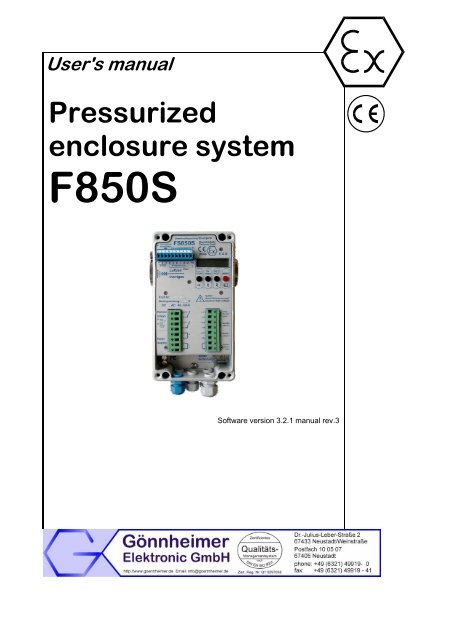
User's manual<br />
<strong>Pressurized</strong><br />
<strong>enclosure</strong> <strong>system</strong><br />
F850S<br />
Software version 3.2.1 manual rev.3
F850S Table of contents Page 2<br />
Contents<br />
1 OPERATION INSTRUCTION FOR EXPLOSION PROTECTED DEVICE......................................................4<br />
2 INTRODUCTION: PRESSURIZED ENCLOSURE SYSTEM F850S ..............................................................5<br />
2.1 Explosion protection: pressurized <strong>enclosure</strong>................................................................................................5<br />
2.2 <strong>Pressurized</strong> <strong>enclosure</strong> <strong>system</strong> according EN50016, second release (5/1996) ...........................................5<br />
2.3 <strong>Pressurized</strong> <strong>enclosure</strong> <strong>system</strong> F850S..........................................................................................................5<br />
2.3.1 Mo<strong>de</strong> pressurization using leakage compensation ...............................................................................5<br />
2.3.2 Mo<strong>de</strong> pressurization using Continuous flow..........................................................................................6<br />
2.3.3 F850S -Application using „Containment Systems“................................................................................7<br />
2.4 Peripherals....................................................................................................................................................7<br />
2.4.1 Operating panels ...................................................................................................................................7<br />
2.4.2 Disconnector unit SR852 and SR853 ...................................................................................................7<br />
2.5 Features in operation zone 21 (Dust)...........................................................................................................8<br />
2.5.1 Purging period -> cleaning period: cleaning the housing insi<strong>de</strong> ...........................................................8<br />
2.5.2 Additional marking .................................................................................................................................8<br />
2.6 Additional information: EC- type certificate F850-SYST...............................................................................9<br />
2.7 Conformity with standards ............................................................................................................................9<br />
2.8 Transport, Storing, Disposal and Repairs ....................................................................................................9<br />
3 INSTALLATION AND CONNECTION...........................................................................................................10<br />
3.1 Mounting .....................................................................................................................................................10<br />
3.1.1 Control unit FS 850S ...........................................................................................................................10<br />
3.1.2 Solenoid valves ...................................................................................................................................10<br />
3.1.3 Operating panels BT 8xx.x ..................................................................................................................10<br />
3.1.4 Disconnector units SR852 / SR853.....................................................................................................11<br />
3.2 Connecting and Commissioning.................................................................................................................11<br />
3.2.1 Connection <strong>de</strong>tails ...............................................................................................................................11<br />
3.2.2 Terminal <strong>de</strong>scription FS 850S .............................................................................................................12<br />
3.2.3 Power off relays...................................................................................................................................12<br />
3.2.4 Commissioning and parameter <strong>de</strong>faults..............................................................................................13<br />
3.2.5 Reset ...................................................................................................................................................13<br />
3.2.6 Purging process...................................................................................................................................13<br />
3.3 Maintenance ...............................................................................................................................................14<br />
3.4 Repairs........................................................................................................................................................14<br />
4 OPERATION ..................................................................................................................................................15<br />
4.1 Human interface .........................................................................................................................................15<br />
4.1.1 Display.................................................................................................................................................15<br />
4.1.2 Keyboard .............................................................................................................................................15<br />
4.2 How to enter and leave the bypass mo<strong>de</strong> ..................................................................................................16<br />
4.3 Indications during normal operation ...........................................................................................................17<br />
4.4 Configuration ..............................................................................................................................................17<br />
4.4.1 The menu structure .............................................................................................................................17<br />
4.4.2 Description of the menu items.............................................................................................................18<br />
4.4.3 Configuration Example ........................................................................................................................20<br />
4.5 Alarm and malfunction indications..............................................................................................................22<br />
5 FLOW CHARTS.............................................................................................................................................23<br />
6 APPENDIX .....................................................................................................................................................28<br />
6.1 Tables .........................................................................................................................................................28<br />
6.2 Type co<strong>de</strong> ...................................................................................................................................................28<br />
6.3 Technical Details ........................................................................................................................................30<br />
6.4 Marking .......................................................................................................................................................30<br />
6.5 Block diagrams ...........................................................................................................................................31<br />
6.6 Dimensions .................................................................................................................................................32<br />
Gönnheimer Elektronic GmbH phone: +49 (6321) 49919-0; fax: -41 Email: info@goennheimer.<strong>de</strong>
F850S Table of contents Page 3<br />
6.7 Sequence of operation diagram .................................................................................................................33<br />
6.8 List of Parameters.......................................................................................................................................34<br />
6.9 Additions/changes of the manual for F850S, option: Decrease of pressure signal alarm .........................35<br />
The symbols WARNING, CAUTION, NOTE<br />
This symbol warns of a serious hazard. Failure to observe this warning<br />
may result in <strong>de</strong>ath or the <strong>de</strong>struction of property.<br />
This symbol warns of a possible failure. Failure to observe this caution<br />
may result in the total failure of the <strong>de</strong>vice or the <strong>system</strong> or plant<br />
to which it is connected.<br />
This symbol highlights important information.<br />
Safety Measures: to read and to comply<br />
Warning! Extreme caution is advised when handling this <strong>de</strong>vice.<br />
High electrical discharge is possible and can be fatal.<br />
Work on electrical installations and apparatus in operation is generally forbid<strong>de</strong>n in<br />
hazardous locations, with the exception of intrinsically safe circuits. In special cases<br />
work can be done on non-intrinsically safe circuits, on the condition that during the<br />
duration of such work no explosive atmosphere exists.<br />
Only explosion protected certified measuring instruments may be used to ensure<br />
that the apparatus is voltage-free. Grounding and short-circuiting may only be carried<br />
out, if there is no explosion hazard at the grounding or short circuit connection.<br />
Danger of static charge!<br />
Clean only with humid cloth!<br />
Do not open when an explosive dust atmosphere is present!<br />
Gönnheimer Elektronic GmbH phone: +49 (6321) 49919-0; fax: -41 Email: info@goennheimer.<strong>de</strong>
F850S <strong>Pressurized</strong> <strong>enclosure</strong> <strong>system</strong> F850S Page 4<br />
1 Operation instruction for Explosion protected <strong>de</strong>vice<br />
Application and Standards<br />
This instruction manual applies to explosion-protected <strong>de</strong>vices of types below. This apparatus is only to be<br />
used as <strong>de</strong>fined and meets requirements of EN 60 079 particularly EN60 079-14 "electrical apparatus for potentiality<br />
explosive atmospheres".<br />
Use this manual in hazardous locations, which are hazardous due to gases and vapours according to the<br />
explosion group and temperature class as stipulated on the type label. When installing and operating the explosion<br />
protected distribution and control panels you should observe the respective nationally valid regulations<br />
and requirements.<br />
General Instructions<br />
Work on electrical installations and apparatus in operation is generally forbid<strong>de</strong>n in hazardous locations, with<br />
the exception of intrinsically safe circuits. In special cases work can be done on non-intrinsically safe circuits,<br />
on the condition that during the duration of such work no explosive atmosphere exists.<br />
Only explosion protected certified measuring instruments may be used to ensure that the apparatus is voltage-free.<br />
Grounding and short-circuiting may only be carried out, if there is no explosion hazard at the<br />
grounding or short circuit connection.<br />
To achieve an impeccable and safety <strong>de</strong>vice operation, please take care for a<strong>de</strong>pt transportation, storage<br />
and mounting, as well as accurate service and maintenance. Operation of this <strong>de</strong>vice should only be implemented<br />
by authorised persons and in strict accordance with local safety standards.<br />
The electrical data on the type label and if applicable, the "special conditions" of the test certificate BVS 06<br />
ATEX E 088are to be observed.<br />
For outdoor installation it is recommen<strong>de</strong>d to protect the explosion protected distribution and control panel<br />
against direct climatic influence, e.g. with a protective roof. The maximum ambient temperature is 40°C, if<br />
not stipulated otherwise.<br />
Terminal compartment in Increased Safety<br />
When closing, it is to be ensured that the gaskets of the terminal compartment remain effective, thus maintaining<br />
<strong>de</strong>gree of protection IP 54 according to EN 60529. Close unused entries by impact-proof stopping<br />
plugs, which are secured against self-loosening and turning.<br />
Do not open the <strong>de</strong>vice in Ex area, as long the <strong>de</strong>vice is energized.<br />
Insi<strong>de</strong> area with explosive dust do clean the inner of the housing of the dust before closing the housing.<br />
Maintenance Work<br />
The gaskets of Ex e <strong>enclosure</strong>s are to be checked for damages and replaced, if required. Terminals,<br />
especially in the Ex e chamber are to be tightened. Possible changes in colour point to increased temperature.<br />
Cable glands, stopping plugs and flanges are to be tested for tightness and secure fitting.<br />
Intrinsically Safe Circuits<br />
Erection instructions in the testing certificates of intrinsically safe apparatus are to be observed. The<br />
electrical safety values stipulated on the type label must not be excee<strong>de</strong>d in the intrinsically safe circuit.<br />
When interconnecting intrinsically safe circuits it is to be tested, whether a voltage and/or current addition<br />
occurs. The intrinsic safety of interconnected circuits is to be ensured. (EN 60079-14, section 12)<br />
Gönnheimer Elektronic GmbH phone: +49 (6321) 49919-0; fax: -41 Email: info@goennheimer.<strong>de</strong>
F850S <strong>Pressurized</strong> <strong>enclosure</strong> <strong>system</strong> F850S Page 5<br />
2 Introduction: <strong>Pressurized</strong> <strong>enclosure</strong> <strong>system</strong> F850S<br />
2.1 Explosion protection: pressurized <strong>enclosure</strong><br />
The use of pressurized <strong>enclosure</strong>s allows the operation of ‘non explosion protected’ <strong>de</strong>vices in<br />
hazardous areas insi<strong>de</strong> zone 1 and zone 2. The protection type ‘pressurisation’ is based on the<br />
principle of maintaining a constant pressure using air or a protective gas to prevent an explosive<br />
mixture forming near the <strong>de</strong>vice insi<strong>de</strong> the pressurized <strong>enclosure</strong>.<br />
Before start-up, the pressurized <strong>enclosure</strong> must be purged with air or protective gas to remove<br />
any explosive mixture that may be insi<strong>de</strong> the <strong>enclosure</strong>.<br />
2.2 <strong>Pressurized</strong> <strong>enclosure</strong> <strong>system</strong> according EN50016, second release (5/1996)<br />
According EN50016 second release from May 1996 is only those pressurized <strong>enclosure</strong> <strong>system</strong><br />
allowed, which is safety examined according EN 954-1.<br />
The FS 850 S reaches the category 3 according EN 954-1 [4] (single fault evaluation). That<br />
means that a single arbitrary fault can occur without losing the safety functionality.<br />
2.3 <strong>Pressurized</strong> <strong>enclosure</strong> <strong>system</strong> F850S<br />
The pressurized <strong>enclosure</strong> <strong>system</strong> F850S contains at least the control unit FS 850S and a solenoid<br />
valve. Each can be mounted in- or outsi<strong>de</strong> the <strong>enclosure</strong>. Furthermore several remote controls<br />
(operation panels) are available to improve ease of operation. It is also possible to connect<br />
intrinsically safe sensors to the control unit FS 850S.<br />
The pressurized <strong>enclosure</strong> <strong>system</strong> F850S operates in two different mo<strong>de</strong>s: Pressurization using<br />
leakage compensation and Pressurization using continuous flow of protective gas.<br />
2.3.1 Mo<strong>de</strong> pressurization using leakage compensation<br />
After purging, the control unit FS 850S holds the pressure insi<strong>de</strong> the <strong>enclosure</strong> at a minimum of<br />
0,8 mbar. Two different solenoid vale techniques are available: digital working solenoid valve<br />
(DSV) technique or proportional working solenoid valve (PSV) technique.<br />
a) Digital solenoid valve technique<br />
While purging, the DSV is activated and a large amount of purge medium flows insi<strong>de</strong> the <strong>enclosure</strong><br />
through a nozzle with a large cross-section. After purging, the control unit turns off the DSV.<br />
The leakage compensation is ma<strong>de</strong> by a bypass choke, with a very small adjustable crosssection<br />
(diameter 0,3 ...1 mm), insi<strong>de</strong> the valve. The protective medium that flows into the <strong>enclosure</strong><br />
now is a<strong>de</strong>quate to maintain a pressure of at least 0,8 mbar. The pressure is monitored by<br />
the control unit FS 850S. The maximum and minimum pressure of the <strong>enclosure</strong> is programmable.<br />
For purging, a traditional and a new integrating method are available:<br />
1. Using the traditional method the purge quantity is a product of a pre-set minimum of flow<br />
rate and time. The flow rate <strong>de</strong>pends on the size of the internal nozzle (diameter 1 ...6 mm)<br />
of the valve and can be specified by matched charts. The common rule of purging must be<br />
consi<strong>de</strong>red: let in minus leakage loss is bigger than flow minimum. This purging method is<br />
called as time based purging method.<br />
2. In contrast to the traditional one the integrating purging method measures the real volume<br />
flow through the <strong>enclosure</strong> outlet and adds it up to get the real purge volume. Also, the<br />
flow rate is monitored, <strong>de</strong>pending on the size of the plate orifice of the control unit. If the<br />
flow rate sinks below its minimum, it will be ignored and it will not contribute to volume integration.<br />
Therefore we achieve a safe and economical purging method. See also Figure_1.<br />
Gönnheimer Elektronic GmbH phone: +49 (6321) 49919-0; fax: -41 Email: info@goennheimer.<strong>de</strong>
F850S <strong>Pressurized</strong> <strong>enclosure</strong> <strong>system</strong> F850S Page 6<br />
Pressure insi<strong>de</strong> the <strong>enclosure</strong> will be observed by each purging method.<br />
The digital solenoid valve technique has a consi<strong>de</strong>rable disadvantage: during purging process<br />
and normal operation, a constant rate of protective gas is nee<strong>de</strong>d. For safety reasons the rate<br />
must be larger than leakage rate of the <strong>enclosure</strong>. Wasting protective gas causes high costs in<br />
many applications.<br />
Figure 1: Consumption of protective gas<br />
b) Proportional solenoid valve technique<br />
Using proportional solenoid valve technique prevents unnecessary wasting protective gas. The<br />
internal proportional working sensory equipment and a proportional valve as actuator are combined<br />
to a pressure feedback control <strong>system</strong>.<br />
The benefits of pressure feedback control are:<br />
1. Consi<strong>de</strong>rable less consumption of protective gas - additional costs for proportional valve<br />
will be amortised soon<br />
2. Increased service reliability achieved by constant pressure insi<strong>de</strong> <strong>enclosure</strong> - increasing<br />
leakage caused by e.g. ageing of the <strong>enclosure</strong> will be balanced and sud<strong>de</strong>n failure is prevented<br />
3. Almost no flow noise and only a small protective gas consumption using a solid <strong>enclosure</strong><br />
Another advantage using a proportional solenoid valve is; that pressure control is also used during<br />
purging. A set-point pressure will be achieved in the <strong>enclosure</strong>, while the flow volume, that<br />
leaves the <strong>enclosure</strong>, will be recor<strong>de</strong>d and integrated through time, until the required purge volume<br />
is achieved. Advantages of this method are:<br />
1. A <strong>de</strong>finite pressure while purging - pressure sensitive parts of the <strong>enclosure</strong>, like membrane<br />
switch panels or windows, will not be overloa<strong>de</strong>d.<br />
2. Purge volume accuracy is achieved by integration of the purge medium flow volume at the<br />
outlet. Wasting purge medium is no more a topic of today.<br />
2.3.2 Mo<strong>de</strong> pressurization using Continuous flow<br />
The control unit FS 850S incorporates the operation mo<strong>de</strong> „continuous flow“. This operation<br />
mo<strong>de</strong> is necessary, for example if an analyser produces an explosive atmosphere insi<strong>de</strong> the <strong>enclosure</strong><br />
(containment <strong>system</strong>). The operation mo<strong>de</strong> continuous flow flushes the <strong>enclosure</strong> permanently.<br />
After the (pre-) purging procedure (purging process) a set-point flow rate is adjusted during<br />
normal operation. The monitored flow rate minimum is adjustable. The continuous flow operation<br />
mo<strong>de</strong> can be realised using 2 digital solenoid valves as well as using one proportional solenoid<br />
valve.<br />
Gönnheimer Elektronic GmbH phone: +49 (6321) 49919-0; fax: -41 Email: info@goennheimer.<strong>de</strong>
F850S <strong>Pressurized</strong> <strong>enclosure</strong> <strong>system</strong> F850S Page 7<br />
2.3.3 F850S -Application using „Containment Systems“<br />
„Containment Systems“ are <strong>de</strong>fined as parts of a <strong>de</strong>vice within a pressurized <strong>enclosure</strong>, which<br />
could emit combustible gas (or occasionally an explosive environment: zone 1, explosive mixture)<br />
from within the <strong>enclosure</strong>.<br />
In or<strong>de</strong>r to receive an Ex p-System including a „Containment System“, which is failsafe according<br />
EN 50016, with the attribute 'no emission', the following conditions must be met:<br />
1. The flammable substance insi<strong>de</strong> the containment <strong>system</strong> is in the gas or vapour phase<br />
when operating between the specified temperature limits<br />
2. The minimum pressure specified for pressurized <strong>enclosure</strong> is at least 50 Pa higher than the<br />
maximum pressure specified for the containment <strong>system</strong><br />
3. An automatic safety <strong>de</strong>vice initiates, if the pressure difference falls below 50 Pa.<br />
This automatic safety <strong>de</strong>vice can be activated by a difference pressure switch, looped into the external<br />
alarm loop (terminal 4/10 on FS 850S). If an alarm occurs on this loop, the control <strong>de</strong>vice<br />
FS 850S will turn off the ignition-capable <strong>de</strong>vice immediately. After alarm cancelling the control<br />
<strong>de</strong>vice FS 850S starts operation automatically with the purging procedure. The external alarm<br />
loop is ma<strong>de</strong> by a normal closed connection method.<br />
2.4 Peripherals<br />
2.4.1 Operating panels<br />
For the control unit FS 850S several operating and visualising panels are available. These panels<br />
consist of the explosion protection class 'intrinsically safe' and are consi<strong>de</strong>rably advantageous,<br />
particularly when the control unit is mounted insi<strong>de</strong> the <strong>enclosure</strong>.<br />
1. Common operating panels: BT 854.1 and BT 855.1 with<br />
• On/Off-Switch<br />
• Key-operated switch for bypass<br />
• LED-indicator for READY and ON<br />
The connection to the control unit consists of 6 wires.<br />
2. Intelligent operating panel type BT 851<br />
This operation panel indicates operation and malfunction reports as plain text. The 4 membrane<br />
switches offer total command of the control unit. Status, momentary pressure, flow rate as well as<br />
remaining purge time are always available.<br />
The connection to the control unit consists of only 3 wires.<br />
Alarm signal lamp on BT851<br />
The red alarm signal lamp (LED) is just below the Display. The lamp is blinking, if the pressure<br />
insi<strong>de</strong> of the cabinet is below the programmed minimum pressure. The lamp is continuously on<br />
while the FS850S is switched into BYPASS mo<strong>de</strong>. In normal operation the alarm signal lamp is<br />
dark.<br />
2.4.2 Disconnector unit SR852 and SR853<br />
According to EN 50016 all non- intrinsically safe connections of the ignition capable apparatus<br />
must be disconnect, if the protection gas pressure falls below the safety limit. In many applications<br />
more than the two connector terminals on the control unit FS 850S are nee<strong>de</strong>d. In these<br />
cases the disconnector unit SR 852, with 8 respectively 16 galvanically separated connectors, is<br />
consi<strong>de</strong>rable helpful.<br />
The S853 provi<strong>de</strong>s a switching power of 250V, 16 A.<br />
Gönnheimer Elektronic GmbH phone: +49 (6321) 49919-0; fax: -41 Email: info@goennheimer.<strong>de</strong>
F850S <strong>Pressurized</strong> <strong>enclosure</strong> <strong>system</strong> F850S Page 8<br />
2.5 Features in operation zone 21 (Dust)<br />
2.5.1 Purging period -> cleaning period: cleaning the housing insi<strong>de</strong><br />
In zone 21 the housing must not be purged in comparison to the operation in gas zone 1. The<br />
operator has to insert the purging volume zero “0 [l]” into the parameter menu.<br />
Purging in the presence of combustible dust would generate a dangerous explosive atmosphere<br />
insi<strong>de</strong> the cabinet.<br />
In the zone 21 the purging period is replaced by a cleaning period, viz. the operator has to remove<br />
thoroughly the combustible dust insi<strong>de</strong> before he is energizing the electrical parts insi<strong>de</strong> the<br />
cabinet.<br />
After cleaning the pressure insi<strong>de</strong> of the cabinet prevent an infiltration of dust.<br />
2.5.2 Additional marking<br />
The cabinet must contain a well viewable sign with the following content:<br />
„WARNING: REMOVE ALL DUST FROM THE INSIDE OF THE ENCLOSURE BEFORE<br />
CONNECTING OR RESTORING THE ELECTRICAL SUPPLY“<br />
On Ex p cabinets suitable for zone 21, which can be opened without tools, has to be placed the<br />
following mark:<br />
„WARNING: DO NOT OPEN WHILE ENERGIZED UNLESS IT IS OBVIOUS THAT NO<br />
COMBUSTIBLE DUST IS PRESENT“<br />
Gönnheimer Elektronic GmbH phone: +49 (6321) 49919-0; fax: -41 Email: info@goennheimer.<strong>de</strong>
F850S <strong>Pressurized</strong> <strong>enclosure</strong> <strong>system</strong> F850S Page 9<br />
2.6 Additional information: EC- type certificate F850-SYST<br />
Gönnheimer features as manufacturer of Ex p- Systems a comprehensive ATEX Ex p- SYSTEM<br />
Certification of a notified body.<br />
Provi<strong>de</strong>s a economical solution for small quantities<br />
⌧ certified for Ex- Zone 1<br />
⌧ enhanced for Dust- Ex, Zone 21 (category 2D)<br />
⌧ the first ATEX certification of this type in Europe<br />
⌧ matches > 80% of all individual customer <strong>system</strong>s<br />
⌧ enhanced pressure ranges: 27mbar, 350mbar and 1 bar<br />
Costumer advantages:<br />
+ usual <strong>de</strong>livery time, + usual quality,+ usual costs,+ no additional efforts<br />
2.7 Conformity with standards<br />
The explosion proof <strong>de</strong>vice type FS850S meets requirements of listed standards in the attachment (Declaration<br />
of conformity). They were <strong>de</strong>veloped, manufactured and tested in accordance with state-of-the-art engineering<br />
practice and ISO9001:2008.<br />
2.8 Transport, Storing, Disposal and Repairs<br />
Transport<br />
Vibration-free in origin package, do not drop, handle carefully<br />
Storing<br />
Store the <strong>de</strong>vice dry, insi<strong>de</strong> of the origin package<br />
Disposal<br />
Repairs<br />
When the explosion proof multipurpose distribution, switching and control units are<br />
eventually disposed of, the national regulations governing the disposal of waste materials<br />
in the country concerned must be rigorously observed.<br />
Defective parts may only be replaced by the Manufacturer or by personnel specially<br />
trained and supervised by the Manufacturer. Only genuine spare parts from the Manufacturer<br />
may be fitted.<br />
Gönnheimer Elektronic GmbH phone: +49 (6321) 49919-0; fax: -41 Email: info@goennheimer.<strong>de</strong>
F850S 3 Mounting and Connection Page 10<br />
3 Installation and connection<br />
This Chapter contains important steps for mounting, connecting and starting.<br />
3.1 Mounting<br />
3.1.1 Control unit FS 850S<br />
The control unit FS 850S can be placed insi<strong>de</strong> a hazardous area. The location (insi<strong>de</strong> or outsi<strong>de</strong><br />
the <strong>enclosure</strong>) as well as the position is almost arbitrary. Only intake and outlet of the control unit<br />
should be lined up on a horizontal axis. See also Figure 12 in the Appendix.<br />
The control unit has 4 holes on the rear plate for mounting, although fixing only with the screw<br />
connection of intake or outlet is sufficient.<br />
The solenoid valve(s) and the control unit (respectively<br />
pressure monitor) should be mounted on the <strong>enclosure</strong><br />
as far away from each other as possible (E.g. space diagonal<br />
arrangement), to achieve a total purging.<br />
Observe local safety gui<strong>de</strong>lines and the regulative DIN<br />
EN 60079-14.<br />
The inner diameter of a pipe connected to the air in- or<br />
outlet of the FS850S must be one and a half time (1,5 x )<br />
bigger than the orifice plate insi<strong>de</strong> of the FS850S.<br />
Keep the air pipes as short as possible<br />
3.1.2 Solenoid valves<br />
The solenoid valves can be mounted insi<strong>de</strong> or outsi<strong>de</strong> the <strong>enclosure</strong>. For mounting position see<br />
manufacturer's gui<strong>de</strong>.<br />
3.1.3 Operating panels BT 8xx.x<br />
Operating panel BT 851.0<br />
The Operating panel BT 851.0 is mounted, without rear plate, directly on the <strong>enclosure</strong>. For<br />
mounting and bushing of the wire, several holes must be ma<strong>de</strong>. For location and drill size see<br />
Figure 13: Dimensions and template BT 851in appendix.<br />
Operating panel BT 851.5<br />
The operating panel BT 851.5 has housing with environment protection IP 65. It can be located<br />
anywhere in hazardous area zone 1. For location and drill size see Figure 13: Dimensions and<br />
template in appendix.<br />
Operating panel BT 854.x<br />
The operating manual BT 854.x consists only of 2 LEDs and an ON/OFF-switch, directly fixed on<br />
the <strong>enclosure</strong>. The BT 854.1 has an additional key-operated switch for bypass. For location and<br />
drill size see Figure 14: Dimensions BT 855, template BT 854 in appendix.<br />
Operating panel BT 855.x<br />
The operating panel BT 855.5 has housing with environment protection IP 65. It can be located<br />
anywhere in hazardous area zone 1. For location and drill size see Figure 14: Dimensions BT<br />
855, template BT 854 in appendix.<br />
Gönnheimer Elektronic GmbH phone: +49 (6321) 49919-0; fax: -41 Email: info@goennheimer.<strong>de</strong>
F850S 3 Mounting and Connection Page 11<br />
3.1.4 Disconnector units SR852 / SR853<br />
The disconnector unit SR852 / SR853 can be mounted and operated in hazardous area zone 1. It<br />
represents an Ex-e terminal box.<br />
3.2 Connecting and Commissioning<br />
After mounting, connect the 'intrinsically safe' peripherals to terminal 1-10, and the power supply,<br />
valves and ignition-capable apparatus to increased safety terminals of the control unit.<br />
Figure 2: Block diagram FS850S<br />
3.2.1 Connection <strong>de</strong>tails<br />
LINE VOLTAGE !<br />
Extreme caution is advised when handling this <strong>de</strong>vice.<br />
High electrical discharge is possible and can be fatal.<br />
Please note the following Standard of Compliance:<br />
BVS 06 ATEX E 088 and the regulative DIN EN 60079-14.<br />
Do not exceed terminal safety limits of each terminal.<br />
See limits in technical <strong>de</strong>tails or <strong>de</strong>clarations of conformity.<br />
If the BT854.1 or BT855.1 operator panel is being used, the bypass function<br />
can be activated via an external key switch. In this case set the bypass co<strong>de</strong><br />
to 9999 to prevent a secondary bypass function by bypass co<strong>de</strong> directly from<br />
the control unit. The key switch is to be connected to terminals 4 and 5 of the<br />
control unit.<br />
Gönnheimer Elektronic GmbH phone: +49 (6321) 49919-0; fax: -41 Email: info@goennheimer.<strong>de</strong>
F850S 3 Mounting and Connection Page 12<br />
If external operation panels BT 81x or additional pressure monitor are not<br />
used, it is possible to connect terminal 4 and 6 of the control unit FS 850S to a<br />
shorting bridge, to enable an automatic switch after purging process.<br />
In this case, the On/Off-function of the far left button on the control unit FS<br />
850S is non- operational.<br />
3.2.2 Terminal <strong>de</strong>scription FS 850S<br />
Terminal<br />
FS850S<br />
1<br />
2<br />
3<br />
4<br />
5<br />
6<br />
7<br />
8<br />
9<br />
4<br />
10<br />
BT 85x<br />
SR 852<br />
1<br />
2<br />
3<br />
4<br />
5<br />
6<br />
7<br />
8<br />
9<br />
Description<br />
Terminals exclusively for connecting the operating panel BT 851<br />
Terminals of operating panel BT 813, BT 814 and BT 815<br />
External alarm loop (intrinsically safe), opening circuit alarms Ex p-System<br />
and switching off ignition-capable <strong>de</strong>vice.<br />
11,12 Working current circuit 1<br />
13,14 Working current circuit 2<br />
15,16 - Line voltage, either neutral conductor at AC or minus pole at DC<br />
17,18 + Line voltage, either outer conductor at AC or plus pole at DC<br />
19,20 + ,- Terminals for proportional solenoid valve<br />
21,22 +,- Terminals for additional solenoid valve 2<br />
respective signal pressure alarm (Option: FS850S.x.x.1)<br />
23,24 +,- Terminals for digital solenoid valve 1<br />
25,26 Terminals for solenoid valve fuse insi<strong>de</strong> FS 850S<br />
3.2.3 Power off relays<br />
The maximum current limits (5 A) on the clamps<br />
11,12 and 13,14 should not be excee<strong>de</strong>d at any time!<br />
E.G. By an application of switched power supply a multiple higher current as<br />
the nominal max. current may occur. In this case a switching on current limitation<br />
(e.g., NTC) must be ad<strong>de</strong>d to avoid the off-limits high current.<br />
If this is missed the risk of wel<strong>de</strong>d relay contacts and within the loss of the<br />
explosion protection exists!!<br />
Gönnheimer Elektronic GmbH phone: +49 (6321) 49919-0; fax: -41 Email: info@goennheimer.<strong>de</strong>
F850S 3 Mounting and Connection Page 13<br />
3.2.4 Commissioning and parameter <strong>de</strong>faults<br />
The following parameters are pre-set after connecting the FS850S to mains supply:<br />
Structure<br />
Co<strong>de</strong>s<br />
Pressure<br />
and<br />
flow<br />
Parameter Display Text Comment<br />
Mo<strong>de</strong>: leakage compensation<br />
Purging method: time based<br />
Type of valve: proportional<br />
Main menu (M-Co<strong>de</strong>)<br />
Bypass (By-Co<strong>de</strong>)<br />
On/Off-Co<strong>de</strong> (On/Off-C.)<br />
Purging time<br />
Purging volume<br />
Min. flow while purging<br />
Min. flow while operating<br />
Flow set-point<br />
Min. pressure insi<strong>de</strong> <strong>enclosure</strong><br />
Max. press. insi<strong>de</strong> <strong>enclosure</strong><br />
Set-point press. while purging<br />
Set-point press. while operating<br />
0001<br />
0002<br />
0000<br />
00-10-00<br />
500.0<br />
1.0<br />
0.5<br />
2.0<br />
0.8<br />
15.0<br />
10.0<br />
2.0<br />
10 [min]<br />
500 [l]<br />
1 [l/s]<br />
0,5 [l/s]<br />
2,0 [l/s]<br />
0,8 [mbar]<br />
15 [mbar]<br />
10 [mbar]<br />
2 [mbar]<br />
The setting 0000 disables the<br />
coding (not in the case of M<br />
co<strong>de</strong>)<br />
The setting 9999 switches off<br />
bypass by coding<br />
time based purging method<br />
selected<br />
integ. purging method selected<br />
time based purging meth.<br />
selected<br />
operation mo<strong>de</strong> continuous<br />
flow selected<br />
proportional solenoid valve<br />
selected<br />
3.2.5 Reset<br />
Press red bottom (ENTER-Button)* while switching on<br />
the control unit FS 850S to reset all parameters to the<br />
values in table above.<br />
*: used only on control unit FS 850S.<br />
RESET<br />
3.2.6 Purging process<br />
The control unit FS 850S starts the purging process immediately after start up, providing the programmed<br />
minimal pressure (minimum 0.8 mbar) is present. Parallel to pressure monitoring, the<br />
flow rate will be watched, to get a safe purging process.<br />
If the purging flow rate passes its minimum (e.g. temporary shut at the outlet), then the purging<br />
process will be interrupted and the control unit continues purging, after the disturbance is gone.<br />
But if purging pressure exceeds the min or max limits then the purging process will be terminated<br />
and the control unit will start a new purging process automatically after achieving purging condition.<br />
The table below shows the minimum flow rate in accordance of the used plate orifice.<br />
Plate orifice in control unit Minimum flow rate<br />
∅ = 4 mm<br />
0,07 liter /sec.<br />
∅ = 6 mm<br />
∅ = 10 mm<br />
∅ = 14 mm<br />
∅ = 18 mm<br />
0,15 liter/sec.<br />
0,35 liter/sec.<br />
0,85 liter/sec.<br />
1,25 liter/sec.<br />
Gönnheimer Elektronic GmbH phone: +49 (6321) 49919-0; fax: -41 Email: info@goennheimer.<strong>de</strong>
F850S 3 Mounting and Connection Page 14<br />
3.3 Maintenance<br />
Depending upon purity of the assigned purging air the inlet and outlet opening of the FS850S must regularly be<br />
examined on impurities (e.g. oil, dust, etc) or corrosion. In case of serious impurities the operator should weigh<br />
the possibility of a punctual appropriate cleaning by Gönnheimer Elektronic GmbH in relation to a spontaneous<br />
loss of the controller.<br />
3.4 Repairs<br />
Repairs of the controller as well as the accessories may be ma<strong>de</strong> only by the Gönnheimer Elektronic GmbH.<br />
Gönnheimer Elektronic GmbH phone: +49 (6321) 49919-0; fax: -41 Email: info@goennheimer.<strong>de</strong>
F850S 4 Operation Page 15<br />
4 Operation<br />
4.1 Human interface<br />
The user has total control of the purging <strong>system</strong> F850S by the use of 4 keys on the control unit<br />
FS 850S respectively by using the external operating panel BT 851. Operation on control unit FS<br />
850S panel BT 851 is equal. Using the other operating panels only a restricted operation is possible.<br />
4.1.1 Display<br />
The built-in display indicates operation mo<strong>de</strong>s, present pressure or flow rate data, as well as malfunction.<br />
4.1.2 Keyboard<br />
The four multi-functional keys have different meanings and functions <strong>de</strong>pend on the present operation<br />
mo<strong>de</strong>.<br />
Key Mo<strong>de</strong> Function<br />
Ein/Aus<br />
normal operation<br />
Toggles the ignition-capable <strong>de</strong>vice on and off, if purging<br />
<strong>system</strong> state is ready<br />
„Shift right“-<br />
button<br />
BYPASS<br />
running menu<br />
normal operation<br />
Shift cursor one position right.<br />
Activates Bypass.<br />
„Up“-button<br />
Fire certificate required !<br />
INFO /P/Q/T<br />
running menu<br />
normal operation<br />
Get menu next item<br />
Changes indication of the display: present pressure, flow<br />
rate, remaining purge time respectively purge volume and<br />
present state of the purging <strong>system</strong><br />
„Down“-button<br />
MENU<br />
running menu<br />
normal operation<br />
Get previous menu item<br />
Executes main menu<br />
„Enter“-button<br />
running menu<br />
Initiates and confirms parameter input<br />
Gönnheimer Elektronic GmbH phone: +49 (6321) 49919-0; fax: -41 Email: info@goennheimer.<strong>de</strong>
F850S 4 Operation Page 16<br />
4.2 How to enter and leave the bypass mo<strong>de</strong><br />
Utilise bypass only, if it is sure that no explosive atmosphere is insi<strong>de</strong><br />
the cabinet!<br />
Fire certificate required !<br />
The bypass mo<strong>de</strong> is <strong>de</strong>nied, if it is possible that a explosive atmosphere<br />
can arise insi<strong>de</strong> the Ex p- housing !<br />
By-CODE<br />
0002<br />
The origin state is normal operation, the Ex p housing can be purged, unpurged<br />
or while purging. The steps shown below are according to the control<br />
<strong>de</strong>vice FS850 not to the operation panel BI851.x.<br />
If you have a operation panel BT81x.1 use the key switch instead.<br />
The bypass co<strong>de</strong> is nee<strong>de</strong>d<br />
The ex works Bypass co<strong>de</strong> is ‘0002’.<br />
Enter is right co<strong>de</strong> using the arrow keys and confirm with the ENTER- key.<br />
Bypass<br />
Or<br />
On<br />
The bypass mo<strong>de</strong> is now active.<br />
If the control unit is set to “automatic on” the display shows “bypass” and<br />
“On” alternately and the relay contacts (Ter. 11,12 and 13,14) are closed.<br />
Now you can toggle the relay contacts by pressing the “right-“ button. Remark:<br />
if the E/A- co<strong>de</strong> is unequal to zero, you must enter them each time<br />
you want to change the relay contacts state.<br />
Leave the bypass mo<strong>de</strong> in the same way as enter.<br />
Gönnheimer Elektronic GmbH phone: +49 (6321) 49919-0; fax: -41 Email: info@goennheimer.<strong>de</strong>
F850S 4 Operation Page 17<br />
4.3 Indications during normal operation<br />
The info-indication shows the present state of the purging <strong>system</strong>. In addition to this indication, it<br />
is possible to select current pressure-, flow rate-, or remaining purge time- indication. See below:<br />
Figure 3 Flow chart: state of purging <strong>system</strong> and corresponding display<br />
4.4 Configuration<br />
You must configure and enter the parameters of the control unit FS850S to achieve a <strong>de</strong>sired<br />
mo<strong>de</strong> of operation. All parameters of the control unit are structured in form of a menu. See also<br />
the flow charts in chapter 5.<br />
4.4.1 The menu structure<br />
Main menu The main menu is sub-divi<strong>de</strong>d into 4 separate categories:<br />
• Language<br />
• Structure<br />
• Parameters<br />
• Co<strong>de</strong>s<br />
Language These are the 5 languages available:<br />
• German<br />
• English<br />
• French<br />
• Dutch<br />
• Spanish<br />
Structure Selecting a purging <strong>system</strong> structure with the following alternatives:<br />
• Operation mo<strong>de</strong> leakage compensation or continuous flow<br />
• Using digital or proportional solenoid valves<br />
• Integration or time based purging method<br />
• Using an additional pressure monitor<br />
• Using the disconnector unit SR852<br />
Gönnheimer Elektronic GmbH phone: +49 (6321) 49919-0; fax: -41 Email: info@goennheimer.<strong>de</strong>
F850S 4 Operation Page 18<br />
Parameters This category contains the necessary parameters <strong>de</strong>pending on the structure<br />
<strong>de</strong>fined above. Examples for parameters are:<br />
• Purging time<br />
• Minimum flow while purging process<br />
• Minimum pressure<br />
• Maximum pressure<br />
Co<strong>de</strong>s The control unit has 3 different co<strong>de</strong> words:<br />
• M-Co<strong>de</strong>: to enter main menu<br />
• By-Co<strong>de</strong>: to activate Bypass<br />
• E/A-Co<strong>de</strong>: to switch ignition-capable apparatus on or off<br />
The FS850S does not working while the main menu is<br />
active. - That means the solenoid valves and the ignition<br />
capable <strong>de</strong>vice insi<strong>de</strong> the cabinet are switched off.<br />
4.4.2 Description of the menu items<br />
The display of the control unit has only 8 digits. For this purpose the names of the structures and<br />
parameters are often abbreviations.<br />
In the following table below are some explanations of the menu items. The table as a reference<br />
gui<strong>de</strong> for programming the <strong>de</strong>sired <strong>system</strong> structure and to set the appropriate parameters correctly.<br />
The menu items are roughly sorted by class.<br />
Please note that the viewable conditions of parameters are not inclu<strong>de</strong>d. The category ‘Language’<br />
is also exclu<strong>de</strong>d, because of it's simplicity.<br />
See also the corresponding flow charts in section 5.<br />
Hierachy<br />
1.Level 2.Level 3.Level Description, Explanation<br />
Structure Valves P-Valve<br />
Param.<br />
Integra.<br />
Cont.Flow<br />
Pur. Time<br />
D-Valve<br />
Integ. Y<br />
Integ. N.<br />
Selecting 'valves’ on level 2 means<br />
that a proportional solenoid valve<br />
or a<br />
digital solenoid valve is available<br />
on level 3<br />
Integration purging method, Yes<br />
Configures integration purging<br />
method.<br />
Integration Purging method, No<br />
Selects time based purging method.<br />
Continuous Flow, Yes<br />
C. Flow Y. Activates the operation mo<strong>de</strong> ‘continuous<br />
flow'.<br />
Continuous Flow, No<br />
C. Flow N. Activates the operation mo<strong>de</strong> ‘leakage<br />
compensation’.<br />
............................... Purge time - Enter a fixed purge<br />
time in h/min/sec. The purge time<br />
only appears, if the time based<br />
purging method is chosen.<br />
Gönnheimer Elektronic GmbH phone: +49 (6321) 49919-0; fax: -41 Email: info@goennheimer.<strong>de</strong>
F850S 4 Operation Page 19<br />
- Option! -<br />
Co<strong>de</strong>s<br />
Pur. Vol.<br />
Min.Fl. P.<br />
Min.Fl .O.<br />
Rated Fl.<br />
Min.Pres.<br />
Max.Pres.<br />
R. Pre. Pu.<br />
Rated Pr.<br />
Sig. Pres<br />
M-Co<strong>de</strong><br />
By-Co<strong>de</strong><br />
On/Off-C.<br />
................................ Purge volume - The purge volume<br />
only appears, if integration purging<br />
method is chosen.<br />
................................ Minimum flow rate during purging<br />
process<br />
................................ Minimum flow rate during operating<br />
................................ Flow rate set-point - In operation<br />
mo<strong>de</strong> ‘continuous flow’ this flow<br />
rate will be regulated, while normal<br />
operation.<br />
................................ Minimum pressure insi<strong>de</strong> <strong>enclosure</strong><br />
Only values above ≥ 0.8 mbar can<br />
be entered. (Additional safety regulativ<br />
to EN 50016)<br />
................................ Maximum pressure insi<strong>de</strong> <strong>enclosure</strong><br />
Maximum pressure ≤ 18 mbar<br />
................................ Pressure set-point during purging,<br />
This pressure value will be regulated<br />
during purging process.<br />
................................ Pressure set-point during normal<br />
operation,<br />
This pressure value will be regulated<br />
during normal operation.<br />
………………………. Signal pressure during normal<br />
operation,<br />
If the housing pressure is below the<br />
signal pressure the Terminals 21/22<br />
are open!<br />
................................ Menu co<strong>de</strong> - Co<strong>de</strong> word to enter<br />
main menu out of operation mo<strong>de</strong>.<br />
The M-co<strong>de</strong> could not switched of<br />
by setting<br />
M-Co<strong>de</strong> =„0000“ .<br />
............................... Bypass co<strong>de</strong> - Co<strong>de</strong> word to activate<br />
the bypass.<br />
The bypass co<strong>de</strong> word can be<br />
switched off by setting „0000“. The<br />
bypass co<strong>de</strong> „9999“ blocks the<br />
bypass function. In that case a bypass<br />
can only be activated by keyoperated<br />
switch on BT 81x.<br />
................................ On/ Off co<strong>de</strong>, enables switching on<br />
or off the ignition-capable <strong>de</strong>vice.<br />
The On/Off co<strong>de</strong> word can be<br />
switched off with „0000“.<br />
Gönnheimer Elektronic GmbH phone: +49 (6321) 49919-0; fax: -41 Email: info@goennheimer.<strong>de</strong>
F850S 4 Operation Page 20<br />
4.4.3 Configuration Example<br />
Example-<br />
Ex p-System<br />
Procedure:<br />
M-Co<strong>de</strong><br />
⇒ Enclosure volume: 500 l<br />
⇒ Language : English<br />
⇒ Structure :<br />
• Operation mo<strong>de</strong>: leakage compensation<br />
• Integration purging method<br />
• Proportional solenoid valve<br />
⇒ Parameters<br />
• Purging volume: 2500 l<br />
• Minimum pressure of <strong>enclosure</strong>: 0.8 mbar<br />
• Maximum pressure of <strong>enclosure</strong>: 12 mbar<br />
• Set-point pressure purging process: 10 mbar<br />
• Set-point pressure normal operation: 1.5 mbar<br />
⇒ Co<strong>de</strong>s<br />
• M- Co<strong>de</strong>: 0100<br />
• By-Co<strong>de</strong>: 1200<br />
• E/A-Co<strong>de</strong>: 0003<br />
Press the Enter-button to start main menu. The control unit calls for the<br />
M-co<strong>de</strong> to be entered.<br />
The ex works M-co<strong>de</strong> is ‘0001’.<br />
Press the Enter-button to insert M-Co<strong>de</strong>.<br />
_000<br />
Display shows ‘0000’, the far left digit is flashing.<br />
Press the key sequence on the left si<strong>de</strong><br />
to enter co<strong>de</strong> ‘0001’,<br />
0001<br />
(the present M-Co<strong>de</strong>).<br />
Confirm the co<strong>de</strong> input pressing Enter-button<br />
Sprache<br />
The main menu is now active. The first sub menu ‘Language’ appears<br />
on the display. The <strong>de</strong>fault language of ex works is German.<br />
To alter the language, press Enter.<br />
Deutsch<br />
On the left appears the word ‘Deutsch’<br />
Press the Up-button to change the language.<br />
English<br />
The language ‘English’ is now selected.<br />
Gönnheimer Elektronic GmbH phone: +49 (6321) 49919-0; fax: -41 Email: info@goennheimer.<strong>de</strong>
F850S 4 Operation Page 21<br />
Press the Enter-key to confirm the change.<br />
Structure<br />
Category ‘Structure’ appears.<br />
Press the Enter-key to configure the Ex p-<strong>system</strong> structure.<br />
Valves<br />
The first item of the structure menu is the choice of the solenoid valve.<br />
Press the Enter-key to change state.<br />
D-Valve<br />
The present state is digital solenoid valve.<br />
Change the state by pressing Up-key -<br />
P-Valve<br />
The new state is now ’Proportional solenoid valve’.<br />
Confirm the change by pressing Enter-key.<br />
Cont.Flow<br />
Param.<br />
Pur. Vol.<br />
This item is the operational mo<strong>de</strong> 'continuos flow' or 'leakage compensation'.<br />
The ex works state is already 'leakage compensation' therefore:<br />
skip this item by pressing the Up- key.<br />
The structure menu is now finished. The main menu continues automatically<br />
with the pre-selected parameters.<br />
Start the parameter category by pressing the Enter- key.<br />
The first menu item ‘Purging volume’ appears.<br />
Press the Enter- key to enter the <strong>de</strong>sired volume ‘2500 l’.<br />
_00500 l<br />
Expecting a pre-set purging volume of 500 l, the input sequence is as<br />
follows:<br />
00_500 l<br />
002500 l<br />
Confirm the input by pressing the Enter- key.<br />
Min Fl. P.<br />
The minimum flow while purging can be increased for special applications.<br />
In this case leave the <strong>de</strong>fault<br />
Gönnheimer Elektronic GmbH phone: +49 (6321) 49919-0; fax: -41 Email: info@goennheimer.<strong>de</strong>
F850S 4 Operation Page 22<br />
Min.Pres<br />
Max.Pres.<br />
012.0mbar<br />
R. Pre. Pu<br />
Rated Pre.<br />
Co<strong>de</strong>s<br />
M-Co<strong>de</strong><br />
By-Co<strong>de</strong><br />
On/Off-C.<br />
End<br />
The <strong>de</strong>sired minimum pressure of 0.8 mbar is already adjusted ex<br />
works. Continue skipping this menu item by pressing the Up- key or<br />
view by pressing the Enter- key.<br />
Now enter the <strong>de</strong>sired value of the maximum pressure. Modify the present<br />
parameter as shown above.<br />
The <strong>de</strong>sired maximum pressure is 12.0 mbar.<br />
The <strong>de</strong>sired set-point pressure during the purging process of 10.0<br />
mbar is already adjusted ex works. Continue passing this menu item by<br />
pressing the up- key.<br />
The <strong>de</strong>sired set-point pressure during normal operation must be adjusted.<br />
Modify the present parameter to 1.5 mbar as shown above.<br />
The parameter category is now finished. The main menu continuous<br />
automatically with the sub menu co<strong>de</strong>s.<br />
Modify M-Co<strong>de</strong> to ‘0100’ as shown above. Please note: the M-Co<strong>de</strong><br />
cannot be set to ‘0000’.<br />
Modify By-Co<strong>de</strong> to ‘1200” as shown above.<br />
Set the On/Off-Co<strong>de</strong> to switch the ignition-capable apparatus on or off<br />
to ‘0003’.<br />
The main menu settings are now complete.<br />
After pressing the Enter- key, the purging <strong>system</strong> is in operation state.<br />
4.5 Alarm and malfunction indications<br />
Alarm Cause Actions<br />
Ext.Alar<br />
The external alarm occurred, i.e. the<br />
external alarm loop is broken. If the<br />
external alarm loop is not used, disable<br />
the external alarm loop by a<br />
shorting bridge.<br />
Fix shorting bridge to terminal 4<br />
and 10 of the control unit FS<br />
850S.<br />
Error message Cause Remedy<br />
Error E.<br />
Error P.<br />
Error F.<br />
Error C.<br />
EEPROM Read Error<br />
Stored configuration data is incomplete<br />
or corrupt.<br />
Pressure sensor Error<br />
The integrated pressure sensors do<br />
not work properly<br />
flow sensor Error<br />
The integrated flow sensors do not<br />
work properly<br />
Hardware - fault<br />
Turn FS 850S off. Turn FS 850S<br />
on. If the error message occurs<br />
again,<br />
then return the control unit FS<br />
850S to Gönnheimer Elektronic.<br />
Gönnheimer Elektronic GmbH phone: +49 (6321) 49919-0; fax: -41 Email: info@goennheimer.<strong>de</strong>
F850S 4 Operation Page 23<br />
5 Flow charts<br />
Figure 4 Flow chart main menu<br />
Gönnheimer Elektronic GmbH phone: +49 (6321) 49919-0; fax: -41 Email: info@goennheimer.<strong>de</strong>
F850S 5 Flow charts Page 24<br />
Figure 5 Flow chart language menu<br />
Gönnheimer Elektronic GmbH phone: +49 (6321) 49919-0; fax: -41 Email: info@goennheimer.<strong>de</strong>
F850S 5 Flow charts Page 25<br />
Figure 6 Flow chart structure category<br />
Gönnheimer Elektronic GmbH phone: +49 (6321) 49919-0; fax: -41 Email: info@goennheimer.<strong>de</strong>
F850S 5 Flow charts Page 26<br />
Figure 7 Flow chart parameter category<br />
Gönnheimer Elektronic GmbH phone: +49 (6321) 49919-0; fax: -41 Email: info@goennheimer.<strong>de</strong>
F850S 5 Flow charts Page 27<br />
Figure 8 Flow chart co<strong>de</strong> category<br />
Gönnheimer Elektronic GmbH phone: +49 (6321) 49919-0; fax: -41 Email: info@goennheimer.<strong>de</strong>
F850S Anhang Seite 28<br />
6 Appendix<br />
6.1 Tables<br />
plate orifice size<br />
Plate orifice<br />
Flow rate is about<br />
[mm]<br />
[m 3 /h]<br />
4 0,5 ... 1,1<br />
6 1,1 ... 2,7<br />
10 2,5 ... 6,5<br />
14 6 ... 11<br />
18 9 ... 15<br />
The right diameter of the plate orifice <strong>de</strong>pends<br />
upon the <strong>de</strong>sired volume flow rate<br />
on the <strong>enclosure</strong> outlet and the built in<br />
nozzle of the solenoid valve. Flow rates<br />
into <strong>enclosure</strong> <strong>de</strong>pend upon primary pressure<br />
and nozzle diameter.<br />
Pressure<br />
Flow rate [l/s] ρ Air = 1,293 kg/m 3<br />
[bar] Nozzle diameter [mm]<br />
[10 5 P 0,3 0,5 0,7 1 1,5 2 3 4 5 6<br />
a]<br />
1,5 0,0275 0,076 0,149 0,304 0,693 1,208 2,676 4,653 7,06 9,796<br />
2 0,0338 0,094 0,184 0,374 0,838 1,48 3,27 5,651 8,511 11,098<br />
2,5 0,0391 0,109 0,213 0,433 0,968 1,708 3,759 6,471 9,685 13,199<br />
3 0,0438 0,0121 0,238 0,484 1,063 1,908 4,186 7,177 10,682 14,445<br />
3,5 0,048 0,133 0,261 0,53 1,195 2,087 4,569 7,804 11,554 15,511<br />
4 0,0518 0,144 0,282 0,573 1,28 2,252 4,917 8,37 12,33 16,441<br />
4,5 0,0554 0,154 0,301 0,612 1,367 2,404 5,239 8,883 13,032 17,263<br />
6.2 Type co<strong>de</strong><br />
Control unit FS850S . .<br />
Mains voltage: 230 VAC ........................ .0<br />
120 VAC ………………. .2<br />
24 VDC .......................... .6<br />
Plate orifice: 4 mm, range 0.5 ...1,1 m 3 /h ...... .0<br />
6 mm, range 1.1 ...2,7 m 3 /h ...... .2<br />
10 mm, range 2.5 ...6,5 m 3 /h ... .4<br />
14 mm, range 6 ...11 m3/h ...... .6<br />
18 mm, range 9 ...15 m3/h ....... .8<br />
More voltages on <strong>de</strong>mand;<br />
Accessories: Additive window in control unit (recommendable, if no operation panel is used)<br />
Operation panels BT<br />
Intelligent operation panel, Ex ib IIC T6,<br />
for mounting on the front<br />
Intelligent operation panel, Ex ib IIC T6,<br />
with IP65 housing<br />
Operation panel, Ex ib IIC T6,<br />
for mounting on the front<br />
with key-operated switch<br />
Operation panel, Ex ib IIC T6,<br />
with IP65 housing<br />
with key-operated switch<br />
BT851.0<br />
BT851.5<br />
BT854.0<br />
BT854.1<br />
BT855.0<br />
BT855.1<br />
Gönnheimer Elektronic GmbH phone: +49 (6321) 49919-0; fax: -41 Email: info@goennheimer.<strong>de</strong>
F850S 6 Annex Page 29<br />
Purge medium valve:<br />
Digital SV . .<br />
Continuous flow<br />
Leakage compensation<br />
..<br />
Nozzle:1 mm<br />
1,5 mm<br />
2 mm<br />
3 mm<br />
4 mm<br />
5 mm<br />
6mm<br />
.D<br />
.L<br />
.1<br />
.1.5<br />
.2<br />
.3<br />
.4<br />
.5<br />
.6<br />
(Ex <strong>de</strong> IIC T4)<br />
Proportional,<br />
suitable for Ex p-<br />
housing size<br />
SVP<br />
Up to 300 l .........<br />
bigger than 300l …<br />
Or<strong>de</strong>r mains voltage in plain text (e.g.SVD.L.2 24VDC)<br />
Fuse for solenoid<br />
valve Nominal Or<strong>de</strong>r.Nr<br />
(Ex-version) 100 mA SI850.0<br />
U Nominal SVP SVD 160mA<br />
200 mA<br />
230<br />
VAC,<br />
220<br />
VAC<br />
120<br />
VAC,<br />
110<br />
VAC<br />
24<br />
VAC,<br />
24 VDC<br />
200mA 100mA 315 mA<br />
500 mA<br />
315mA 160mA 630 mA<br />
1000 mA<br />
1,6 A 630mA 1600 mA<br />
2000mA<br />
.3<br />
.5<br />
SI850.1<br />
SI850.2<br />
SI850.3<br />
SI850.4<br />
SI850.5<br />
SI850.6<br />
SI850.7<br />
SI850.8<br />
Remark: please or<strong>de</strong>r the Ex- solenoid valve fuse separately<br />
Gönnheimer Elektronic GmbH phone: +49 (6321) 49919-0; fax: -41 Email: info@goennheimer.<strong>de</strong>
F850S 6 Annex Page 30<br />
6.3 Technical Details<br />
Control unit FS850S<br />
General Mounting insi<strong>de</strong> hazardous area<br />
Ex- protection class<br />
II 2 G, Ex e mb [ib] [px] IIC T6<br />
II 2D Ex tD [ibD] [pD] A21 IP65 T 70°C<br />
EC- type exam.cert. DMT 99 ATEX E 003<br />
BVS 06 ATEX E 088<br />
Environment protection<br />
IP 65 (Remark: without outlet drill)<br />
Housing Dimensions H x W x D: 220 mm x 120 mm x 90 mm<br />
Material Aluminium, lacquered / Ral 7035<br />
Electrical Power consumption<br />
About 2.5 VA (without peripherals)<br />
specifications<br />
Main voltage<br />
24VDC, 24VAC, 110VAC, 120VAC, 220VAC, 230VAC<br />
48 ...62 Hz<br />
Working circuits<br />
AC: U ≤ 250VAC, I ≤ 5A at cos ϕ > 0,7<br />
Terminal 11, 12, 13,<br />
DC:<br />
14<br />
U ≤ 30 VDC, I ≤ 5 A, P ≤ 150 W<br />
Control circuits<br />
Terminal 1..10<br />
Ex protection class: intrinsically safe Ex ib IIC<br />
see <strong>de</strong>claration of conformity for further <strong>de</strong>tails<br />
Min. and max.<br />
clamping torque<br />
min. 0,3 Nm<br />
max. 0,4 Nm<br />
Min. und Max. wire<br />
cross- section<br />
steep: 0,2 – 2,5 mm²<br />
flexible: 0,2 – 2,5 mm²<br />
Pneumatic Pressure range 0 ... 18 mbar<br />
Flow rate range<br />
0,5.. 15 m 3 /h, <strong>de</strong>pen<strong>de</strong>nt upon plate orifice size<br />
Mounting Position Position in<strong>de</strong>pen<strong>de</strong>nt, only intake and outlet of the control unit<br />
should be lined up on a horizontal axis.<br />
Environment temperature<br />
-10°C ...+50°C at T6<br />
-10°C ...+60°C at T4<br />
Humidity<br />
5-95%, non-con<strong>de</strong>nsing<br />
Ex p<br />
Configuration<br />
Parameter input<br />
LC-Display, menu gui<strong>de</strong>d<br />
Different languages : German, English, French, Dutch, Spanish<br />
Storage<br />
by EEPROM double saved with CRC<br />
6.4 Marking<br />
Marking of type FS850S:<br />
II 2 G Ex e mb [ib] [px] IIC T6 -20°C ≤ T A ≤ +45°C<br />
II 2 G Ex e mb [ib] [px] IIC T4 -20°C ≤ T A ≤ +60°C<br />
II 2 D Ex tD [ibD] [pD] A21 IP 65 T70°C -20°C ≤ T A ≤ +60°C<br />
Marking of type FS850S.*.*.*.HT:<br />
II 2 G Ex e mb [ib] [px] IIC T4<br />
-20°C ≤ T A ≤ +70°C<br />
Marking of operator panel BT851:<br />
II 2 G Ex ib IIC T6<br />
II 2 D Ex ibD T80°C<br />
Gönnheimer Elektronic GmbH phone: +49 (6321) 49919-0; fax: -41 Email: info@goennheimer.<strong>de</strong>
F850S 6 Annex Page 31<br />
6.5 Block diagrams<br />
Figure 9 Electrical block diagram<br />
Figure 10 Pneumatic block diagram<br />
Gönnheimer Elektronic GmbH phone: +49 (6321) 49919-0; fax: -41 Email: info@goennheimer.<strong>de</strong>
F850S 6 Annex Page 32<br />
6.6 Dimensions<br />
Figure 11: Dimensions FS 850S<br />
Figure 12: Mounting examples<br />
Figure 13: Dimensions and template BT 851 Figure 14: Dimensions BT 855, template BT 854<br />
Figure 15: Dimensions digital solenoid valve<br />
Figure 16: Dimensions proportional solenoid valve<br />
Gönnheimer Elektronic GmbH phone: +49 (6321) 49919-0; fax: -41 Email: info@goennheimer.<strong>de</strong>
F850S 6 Annex Page 33<br />
6.7 Sequence of operation diagram<br />
Abbildung 17: Flow chart operation diagram<br />
Gönnheimer Elektronic GmbH phone: +49 (6321) 49919-0; fax: -41 Email: info@goennheimer.<strong>de</strong>
F850S 6 Annex Page 34<br />
6.8 List of Parameters<br />
System i<strong>de</strong>ntification<br />
Installation no.:<br />
Date:<br />
FS 850S. . Production no.: Solenoid valve BT 8<br />
Inputs Description Display Value/ state<br />
Language<br />
F850S language<br />
Structure<br />
Valve Solenoid valve type used with<br />
this purging <strong>system</strong>?<br />
Purging<br />
method<br />
Operational<br />
mo<strong>de</strong><br />
Parameters<br />
Time based purging method<br />
(Integ N.) or integration purging<br />
method (Integ. Y.)<br />
Continuous flow (C. flow Y.) or<br />
leakage compensation (C. flow<br />
N.)<br />
Purge time<br />
Purge volume<br />
Language<br />
Tick box<br />
Tick box<br />
Valves<br />
Integra.<br />
Cont. Flow<br />
Tick box<br />
Pur. Time<br />
Pur. Vol.<br />
Minimum flow rate during purging<br />
procedure Min. Fl. P.<br />
P-Valve<br />
<br />
Integ. Y.<br />
<br />
C. Flow Y.<br />
<br />
D-Valve<br />
<br />
Integ. N.<br />
<br />
C. Flow N,<br />
<br />
Co<strong>de</strong>s<br />
Minimum flow rate during normal<br />
operation by op. mo<strong>de</strong><br />
continuous flow<br />
Set-point flow rate by operation<br />
mo<strong>de</strong> continuous flow<br />
Pressure monitor,<br />
minimum pressure<br />
Pressure monitor,<br />
maximum pressure<br />
Set-point pressure during purging<br />
Set-point pressure during normal<br />
operation<br />
Co<strong>de</strong> for main menu<br />
Co<strong>de</strong> for bypass<br />
Co<strong>de</strong> to enable switching ignition-capable<br />
<strong>de</strong>vice<br />
Min.Fl. O.<br />
Rated Fl.<br />
Min. Pres.<br />
Max. Pres<br />
R. Pre. Pu.<br />
Rated Pr.<br />
M-Co<strong>de</strong><br />
By-Co<strong>de</strong><br />
On/Off-C.<br />
Gönnheimer Elektronic GmbH phone: +49 (6321) 49919-0; fax: -41 Email: info@goennheimer.<strong>de</strong>
F850S 6 Annex Page 35<br />
6.9 Additions/changes of the manual for F850S, option: Decrease of pressure<br />
signal alarm<br />
Connection:<br />
Digital valve 2 clamp 22,21<br />
Page 7<br />
Function:<br />
With this option a spontaneous <strong>de</strong>crease of pressure is announced over a passive relay contact.<br />
In the parameter menu of the FS850S the reporting pressure is specified. If the housing<br />
internal pressure falls during the enterprise below this reporting pressure, then the early warning<br />
opens relay contact. This signal can be evaluated problem-free in the control room. The<br />
relay contact is implemented in Ex e clamps, therefore the inquiry signal cannot be intrinsically<br />
safe implemented into the control room.<br />
Tabelle:<br />
Status, operating condition<br />
P > reporting pressure, broad or<br />
Otherwise<br />
Relay contact<br />
Relay contact closed<br />
Relay contact open<br />
Gönnheimer Elektronic GmbH phone: +49 (6321) 49919-0; fax: -41 Email: info@goennheimer.<strong>de</strong>
(Translation)<br />
(1)<br />
EC- TYPE- EXAMINATION CERTIFICATE<br />
(2) – Directive 94/9/EC –<br />
Equipment and protective <strong>system</strong>s inten<strong>de</strong>d for use in<br />
potential explosive Atmospheres<br />
(3) EC- type- examination Certificate number<br />
BVS 06 ATEX E 088<br />
(4) Equipment: <strong>Pressurized</strong> <strong>enclosure</strong> <strong>system</strong> type F 850S and F 860S<br />
(5) Manufacturer: Gönnheimer Elektronic GmbH<br />
(6) Address: D- 67433 Neustadt an <strong>de</strong>r Weinstraße<br />
Dr.-Julius-Leberstr. 2<br />
(7) This equipment and any acceptable variation thereto are specified in the schedule to<br />
this certificate and the documents therein referred to.<br />
(8) The certifying body of the EXAM BBG, notified body No. 0158 in accordance with<br />
Article 9 of the Council Directive 94/9/EC of March 1994, certifies that equipment has<br />
been found to comply with the essential health and safety requirements relating to the<br />
<strong>de</strong>sign and construction of equipment and protective <strong>system</strong>s inten<strong>de</strong>d for use<br />
potentially explosive atmospheres, given in Annex II to the Directive.<br />
The examination and test results are recor<strong>de</strong>d in the confi<strong>de</strong>ntial report No. BVS PP<br />
06.2078 EG<br />
(9) Compliance with to essential health and safety requirements has been assured by<br />
compliance with:<br />
EN 60079-0 :2004 General directives EN60079-2:2004 Type of protection ‚p’<br />
EN 60079-7:2003 Increased Safety ‘e’ FDIS IEC60079-11:2005 Intrinsic Safety ‘i’<br />
EN 60079-18:2004 Moulding ‘m’<br />
IEC61241-0:2004 General requirements<br />
EN 61241-1:2004 Protected by <strong>enclosure</strong>s IEC 61241-11:2005 Protection by intrinsic safety<br />
EN 954-1:1996 Safety of machines - Safety-related parts of control <strong>system</strong>s<br />
(10) If the sign “X” is places after the certificate number, it indicates that the equipment is<br />
subject to special conditions for safe use specified in the schedule to this certificate.<br />
(11) This EC- type- examination Certificate relates only to the <strong>de</strong>sign and construction of<br />
the specified equipment in accordance with Directive 94/9/EC. Further requirements of<br />
this Directive apply to the manufacture and supply of this equipment.<br />
(12) The marking of the equipment shall inclu<strong>de</strong> the following:<br />
II 2 G for FS850S, FS860S and BT851<br />
II 2 D for FS850S and BT851 see Details in 15.1<br />
EXAM BBG- Prüf- und Zertifizier GmbH<br />
Bochum, 25.July 2006<br />
Zertifizierungsstelle<br />
Fachbereich<br />
EC-type-examination Certificates without signature and official stamp shall not be valid. The certificates may be circulated only<br />
without alteration. Extracts or alterations are subject to approval by the EXAM BBG- Prüf- und Zertifizier GmbH<br />
Page 1 of 5
(Translation)<br />
(13) Annex to<br />
(14)<br />
EC- TYPE-Examination CERTIFICATE No.<br />
BVS 06 ATEX E 088<br />
(15) 15.1 Object and type<br />
pressurized <strong>enclosure</strong> <strong>system</strong> type Typ F 850 S und F 860 S<br />
Purge control unit FS850S:<br />
Purge control unit FS850S.*.*.*.HT:<br />
Purge control unit FS860S:<br />
Operator panel BT851:<br />
15.2 Description of equipment<br />
The pressurized <strong>enclosure</strong> <strong>system</strong> type F850S and type F860S serves to build up an<br />
explosion proofed electrical apparatus with ex- protection type pressurized <strong>enclosure</strong><br />
according EN/IEC 60079-2. as well EN/IEC 61241-4. They content of the control unit<br />
FS850S respectively FS860S, the operator panel BT851, as well as additional<br />
<strong>de</strong>vices.<br />
The safety of the function “pressurized <strong>enclosure</strong> <strong>system</strong>” are proved on base EN 954-<br />
1 “Safety of machines - Safety-related parts of control <strong>system</strong>s”. The <strong>system</strong> is<br />
equivalent to category 3 to the named norm.<br />
15.3 Electrical <strong>de</strong>tails<br />
Mains<br />
(Terminals 15 to 18)<br />
Valve fuse<br />
(Terminals 25/26)<br />
Valve terminals<br />
(Terminals 21/22 and 23/24)<br />
Proportional valve terminals<br />
(Terminals 19/20)<br />
230, 220, 120, 110, 24 V AC resp. 24 V DC<br />
Safety maximum voltage U m = 253 V<br />
Appropriate valve fuse type SI850<br />
Maximum voltage as mains<br />
Maximum voltage as mains<br />
EC-type-examination Certificates without signature and official stamp shall not be valid. The certificates may be circulated only<br />
without alteration. Extracts or alterations are subject to approval by the EXAM BBG- Prüf- und Zertifizier GmbH<br />
Page 2 of 5
(Translation)<br />
Relay contacts<br />
(Terminals 11/12 and 13/14<br />
4)<br />
AC<br />
U = 250 V<br />
I = 5 A<br />
cos ϕ = 0,7<br />
DC<br />
U = 30 V<br />
I = 5 A<br />
P = 150 W<br />
Intrinsically safe teriminals<br />
In protection type intrinsic Safety EEx ib IIC<br />
See the highest values of voltage, current and reactance in<br />
table below:<br />
Terminal U 0 I 0 P 0 L 0 C 0<br />
1,9 8,61 V 51 mA 110 mW 10 mH 2 µH<br />
4 8,61 V 10 mA 22 mW 10 mH 2 µH<br />
3 8,61 V 20 mA 44 mW 10 mH 2 µH<br />
5, 6, 10 8,61 V 6 mA 13 mW<br />
2 Ground<br />
All intrinsically safe current circuits (terminal 1 to 10) are<br />
safe gavanically separated up to a nominal voltage of 375 V<br />
to every remaining current circuit.<br />
The permitted ambient temperature range is -20°C .. 45°C in temperature class T6. As<br />
well as -20°C .. 60°C in the temperature class T4.<br />
The control unit type FS850S.x.x.x.HT (temperature class T4 only ) has the permitted<br />
temperature range -20°C .. 70°C<br />
(16) Test report<br />
Report No. BVS PP 06.2078 EG, date 25.07.2006<br />
(17) Special conditions for the save application<br />
none<br />
EC-type-examination Certificates without signature and official stamp shall not be valid. The certificates may be circulated only<br />
without alteration. Extracts or alterations are subject to approval by the EXAM BBG- Prüf- und Zertifizier GmbH<br />
Page 3 of 5
(Translation)<br />
1. Amendment<br />
(completion according to the gui<strong>de</strong>line 94/9/EC addition III figure 6 )<br />
EC- TYPE-Examination CERTIFICATE No.<br />
BVS 06 ATEX E 088<br />
Equipment:<br />
Manufacturer:<br />
Address:<br />
<strong>Pressurized</strong> <strong>enclosure</strong> <strong>system</strong> type F 850S and F 860S<br />
Gönnheimer Elektronic GmbH<br />
D- 67433 Neustadt an <strong>de</strong>r Weinstraße<br />
Description:<br />
The control units of the pressurized <strong>enclosure</strong> <strong>system</strong> can also be manufactured<br />
according to the examination protocol wich are listed in the associated examination<br />
certificate.<br />
The basic safety- and health<strong>de</strong>mands of the changed construction are fulfilled in<br />
accordance to:<br />
EN 60079-0 :2004<br />
EN 60079-7:2003<br />
EN 60079-18:2004<br />
EN 61241-1:2004<br />
EN 954-1:1996<br />
General directives EN60079-2:2004 type of protection ‚p’<br />
Increased Safety ‘e’ FDIS IEC60079-11:2006 Intrinsic Safety ‘i’<br />
Moulding ‘m’<br />
IEC61241-0:2004 General requirements<br />
protected by <strong>enclosure</strong>s IEC 61241-11:2005 Protection by intrinsic safety<br />
Safety of machines - Safety-related parts of control <strong>system</strong>s<br />
The marking of the <strong>de</strong>vice must content the following data<br />
Type FS850S<br />
II 2G Ex e mb [ib] [px] IIC T6 or<br />
II 2G Ex e mb [ib] [px] IIC T4 and<br />
II 2D Ex tD [ibD] [pD] A21 IP65 T 70°C<br />
Type FS850S.*.*.*.HT<br />
II 2G Ex e mb [ib] [px] IIC T4 and<br />
Type FS860S<br />
II 2G Ex e mb [ib] [px] IIC T6 or<br />
II 2G Ex e mb [ib] [px] IIC T4<br />
Type BT851<br />
II 2G Ex ib IIC T6 and<br />
II 2D Ex ibD 21 T 80°C<br />
EC-type-examination Certificates without signature and official stamp shall not be valid. The certificates may be circulated only<br />
without alteration. Extracts or alterations are subject to approval by the EXAM BBG- Prüf- und Zertifizier GmbH<br />
Page 4 of 5
(Translation)<br />
Examination certificate:<br />
BVS PP 06.2078 EG, date 23.10.2006<br />
EXAM BBG Prüf- und Zertifizier GmbH<br />
Bochum, <strong>de</strong>n 23. October 2006<br />
________________<br />
Zertifizierungsstelle<br />
_________________<br />
Fachbereich<br />
EC-type-examination Certificates without signature and official stamp shall not be valid. The certificates may be circulated only<br />
without alteration. Extracts or alterations are subject to approval by the EXAM BBG- Prüf- und Zertifizier GmbH<br />
Page 5 of 5
EG-Konformitätserklärung<br />
Declaration of conformity / Déclaration <strong>de</strong> conformité<br />
Communauté Européenne<br />
Anbieter:<br />
Supplier:<br />
Fournisseur<br />
Anschrift:<br />
Address:<br />
Adresse:<br />
Gönnheimer Elektronic GmbH<br />
Gewerbegebiet Nachtwei<strong>de</strong><br />
Dr.-Julius-Leber-Straße 2<br />
67433 Neustadt/Weinstraße<br />
Produkt:<br />
Product:<br />
Produit:<br />
F850S,<br />
Überdruckkapselungs<strong>system</strong><br />
Das oben beschriebene Produkt erfüllt die Schutzanfor<strong>de</strong>rungen <strong>de</strong>r folgen<strong>de</strong>n EG-Richtlinien<br />
/ the product <strong>de</strong>scribed above complies with the following EG- rules / le produit décrit ci<strong>de</strong>ssus<br />
accomplit CU- réglementations<br />
2004/108/EG, 93/68/EWG, 94/9/EG<br />
und ist konform mit / and is in conformity with / et est conforme á:<br />
EN 60079-0: 2006, Allgemeine Bestimmungen<br />
EN 60079-2: 2007, Überdruckkapselung „p“<br />
EN 60079-7: 2007, Erhöhte Sicherheit „e“<br />
EN 60079-11: 2007, Eigensicherheit „i“<br />
EN 60079-18: 2004, Vergusskapselung „m“<br />
EN 61241-0:2006, Allgemeine Bestimmungen, Staub Ex“<br />
EN 61241-1:2004, Schutz durch Gehäuse „tD“<br />
IEC 61241-11:2005, Eigensichere Betriebsmittel<br />
EN 954-1: 1996, Sicherheit von Maschinen<br />
EN 1127-1: 2008, ATEX- Grundnorm<br />
EN 61000-6-4: 2007, Fachgrundnorm Störaussendung: Industriebereich<br />
EN 61000-6-2: 2006, Fachgrundnorm Störfestigkeit: Industriebereich<br />
EN 60947-1: 2008, Nie<strong>de</strong>rspannungs-Schaltgeräte<br />
zusätzliche Angaben / additional information / informations supplémentaires:<br />
Qualitätsmanagement- System nach ISO EN DIN 9001:2008<br />
Anerkanntes Qualitätssicherungs<strong>system</strong> nach Richtlinie 94/9/EG<br />
EG- Baumusterprüfbescheinigung / EC- Type certification / Attestation d’examen ce <strong>de</strong> type<br />
BVS 06 ATEX E 088<br />
Neustadt, <strong>de</strong>n 28.02.2010<br />
Gönnheimer Elektronic GmbH<br />
EG-Konformitätserklärung; Rev.1


