Your Ceramic Solutions Provider - Gigacomp
Your Ceramic Solutions Provider - Gigacomp
Your Ceramic Solutions Provider - Gigacomp

Create successful ePaper yourself
Turn your PDF publications into a flip-book with our unique Google optimized e-Paper software.
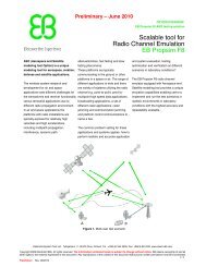
percent of rated power<br />
Flanged Terminations - BeO Free<br />
CW Power<br />
Rating<br />
CFG A B C D E F G H J K<br />
Frequency<br />
Range<br />
Typical<br />
VSWR<br />
Part Number<br />
30 watts B .515 .250 .250 .125 .040 .105 .140 max .062 .130 .370 max DC-2.5 GHz 1.15:1 T 50R0-30-27X<br />
40 watts B .515 .250 .250 .125 .040 .105 .140 max .062 .130 .370 max DC-5.0 GHz 1.20:1 T 50R0-40-13X<br />
40 watts A .800 .230 .350 .560-<br />
.600<br />
.040 .090 .125 max .062 .130 .370 max DC-2.5 GHz 1.20:1 T 50R0-40-14X<br />
50 watts B .515 .250 .250 .125 .040 .090 .125 max .062 .130 .370 max DC-5.0 GHz 1.20:1 T 50R0-50-14X<br />
50 watts A .800 .230 .350 .560-<br />
.600<br />
70 watts A .870 .375 .250 .560-<br />
.600<br />
.040 .105 .140 max .062 .130 .370 max DC-2.0 GHz 1.20:1 T 50R0-50-15X<br />
.040 .090 .125 max .062 .160 .370 max DC-2.75 GHz 1.10:1 T 50R0-70-16X<br />
100 watts A .870 .375 .250 .560 .040 .090 .125 max .062 .160 .370 max DC-2.0 GHz 1.10:1 T 50R0-100-22X<br />
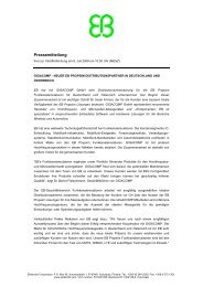
Configuration A<br />
Configuration B<br />
B<br />
G<br />
F<br />
B<br />
G<br />
F<br />
A<br />
C<br />
E<br />
D<br />
C<br />
E<br />
A<br />
D<br />
J DIA<br />
C L<br />
K<br />
H<br />
J DIA<br />
C L<br />
K<br />
H<br />
General Specifications -<br />
Resistive Element ................. Proprietary Thick Film<br />
Substrate .............................. BeO, ALN or BeO Free<br />
Mounting Flange ................... Copper Silver Plated<br />
Leads .................................... Copper (.005” thick) Silver Plated<br />
General Notes -<br />
- All power ratings assume an operating base plate temperature of 100 o C<br />
- All dimension are in inches.<br />
- Resistance Tolerance: standard is +/- 5%; +/-2% available.<br />
- Resistance Range: 0.5 to 20,000 ohms. Standard values: 50 & 100 ohms.<br />
- Mechanical Tolerance: +/-.010, unless otherwise specified.<br />
- Minimum lead length on all devices is .125 inches.<br />
- Individual drawings available upon request.<br />
- Other configurations available, custom requests welcome.<br />
www.barryind.com<br />
Barry Industries, Inc.<br />
60 Walton Street . Attleboro . Massachusetts . 02703 U.S.A.<br />
Tel: +1-508-226-3350 . Fax: +1-508-226-3317 . E-mail: sales@barryind.com<br />
Page 19<br />
100<br />
75<br />
50<br />
25<br />
0<br />
Derating Curve<br />
25 50 75 100 125 150<br />
flange temperature - o C<br />
For operations outside the derating curve, please consult<br />
with one of BARRY’s application engineers.