Product information ELCOVISION 10A - 09/07 E - Geotech
Product information ELCOVISION 10A - 09/07 E - Geotech
Product information ELCOVISION 10A - 09/07 E - Geotech

Create successful ePaper yourself
Turn your PDF publications into a flip-book with our unique Google optimized e-Paper software.
<strong>ELCOVISION</strong> 10 – Full Automatic Image Orientation Module<br />
<strong>ELCOVISION</strong> 10 – The Universal 3D-Photogrammetry System with Full Automatic Image Orientation<br />
<strong>ELCOVISION</strong> 10 the popular photogrammetric evaluation<br />
software package has reached the sixth generation since its<br />
market launch in 1986 being constantly upgraded and<br />
developed to meet user demands includes now a module for full<br />
automatic image orientation. There is no <strong>information</strong> required<br />
about the point of view of the images, the only requirement is<br />
that the pictures must be taken with a calibrated camera. A short<br />
step by step example will show you the process of the automatic<br />
orientation:<br />
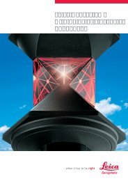
After the orientation of the images is finished the result of the<br />
orientation is displayed:<br />
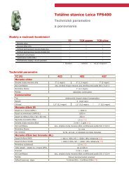
In the first step the images are loaded into a new project and the<br />
automatic orientation is started:<br />
Now it is time for the first and only manual step in the automatic<br />
orientation process. The operator should define a suitable<br />
system of coordinates. This could be done by measuring at least<br />
one known distance or by measuring at least 4 control points.<br />
After starting the automatic orientation <strong>ELCOVISION</strong> 10 starts<br />
analyzing the images for prominent points and classifies them in<br />
an unique way:<br />
As a by-product of the automatic orientation a cloud of points is<br />
generated. These points are normally very accurate surface<br />
points of the object, <strong>ELCOVISION</strong> 10 also provides them with<br />
the true color of the object. This cloud of points could be used<br />
for many applications.<br />
In the next step <strong>ELCOVISION</strong> 10 uses this featured points found<br />
in the first step and runs the automatic orientation using the<br />
traditional relative, absolute and global orientation approach.<br />
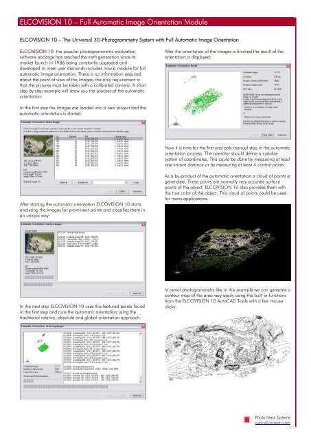
In aerial photogrammetry like in this example we can generate a<br />
contour map of the area very easily using the built in functions<br />
from the <strong>ELCOVISION</strong> 10 AutoCAD Tools with a few mouse<br />
clicks:<br />
Photo Mess Systeme<br />
www.elcovision.com
<strong>ELCOVISION</strong> 10 Technical Data and Function Overview<br />
Image Recognition and Image<br />
Processing<br />
Reads and writes almost all known digital<br />
image formats<br />
Full automatic raw-file converter with<br />
automatic image optimizing for maximum<br />
image quality<br />
Integrated image processing module with<br />
colour and contrast adjustment, gamma<br />
correction etc.<br />
Optimized image display in the magnifier<br />
for easy and precise measurement even<br />
in underexposed or overexposed image<br />
parts.<br />
Réseau Measurement<br />
Fully automatic réseau measurement of<br />
digital images<br />
Fully automatic réseau measurement of<br />
réseau images of metric cameras with<br />
automatically chosen transformation:<br />
affine, helmert, projective or polynomial<br />
Digital Rectification ELSP<br />
Definition of 2D-rectification planes with<br />
known rectangles or arbitrary distance<br />
squares with 5 known distances<br />
Definition of 2D-rectification planes by<br />
perpendicular and parallel lines and at<br />
least one known distance<br />
Linking of 2D-rectification planes among<br />
themselves and also linking them into the<br />
3D-space using 3D-control points<br />
Definition of balanced 3D-rectification<br />
planes using 4 or more 3D-control<br />
points<br />
Arbitrary trimming of the rectification<br />
planes with automatic determination of<br />
the circumference and the area of the<br />
resulting rectification plane<br />
Optional lens distortion correction<br />
Automatic rectification as many as desired<br />
rectification planes into a digital<br />
single picture e.g. an orthophoto<br />
Full automatic generation of 3D-rectification<br />
planes from AutoCAD surface<br />
models<br />
Full automatic transferring of 3D-rectified<br />
textures into AutoCAD<br />
Automatic Image Measurement Modes<br />
Automatic measurement of réseau<br />
crosses with sub pixel precision<br />
Automatic measurement of targeted<br />
points with sub pixel precision<br />
Automatic measurement of corners and<br />
edges<br />
Measuring assistance by epipolar lines<br />
Methods of Orientation<br />
Arbitrary definition of the system of coordinates:<br />
Local by distances and/or<br />
control points, or with control points<br />
within a superior system of coordinates<br />
Full automatic photo orientation<br />
Single and two photo orientation<br />
Multi photo orientation<br />
Bundle adjustment with up to 1000<br />
pictures and simultaneous camera calibration<br />
Orientation of full spherical images<br />
Definition of 3D Planes<br />
Balanced spatial plane by 3 or more 3Dpoints<br />
Definition of parallel planes by points or<br />
with arbitrary distance to other planes<br />
Definition of perpendicular planes to<br />
arbitrary other spatial planes<br />
Measuring Methods for Point<br />
Measurement and CAD Plugin<br />
Rectification Measurement<br />
Mono Photo Measurement: Intersection<br />
of a measuring beam with a 3D-plane<br />
Two Photo Measurement: Balanced<br />
spatial intersection of two measuring<br />
beams<br />
Multi Photo Measurement: Balanced<br />
spatial intersection of two or more measuring<br />
beams<br />
Stereoscopic Measurement: Epipolar<br />
transformation of non stereoscopic images<br />
into a stereo image pair and displaying<br />
them with various methods like<br />
LCD shutter or anaglyph images.<br />
Measurement from full spherical images<br />
CAD Integration<br />
Seamless integrated into the following<br />
CAD Systems, all drawing functions of<br />
the CAD become measurement functions<br />
AutoCAD: Version 14 - 2010<br />
IntelliCAD 2000<br />
BricsCAD V10<br />
Additional CAD Functions<br />
Superimposition of the CAD drawing into<br />
the digital images<br />
Draw perpendiculars with one single<br />
measurement<br />
Measuring and drawing of single segmented<br />
lines<br />
Simultaneous measuring and drawing of<br />
3D-trimmed lines<br />
Simultaneous measuring and drawing of<br />
3D-balanced lines<br />
Simultaneous measuring and drawing of<br />
UCS aligned lines<br />
Circle intersection construction function<br />
Drawing of 3D-circles and circular arcs<br />
with three 3D-measurements with plausibility<br />
check<br />
Drawing 3D-rectangles with three 3Dmeasurements<br />
with plausibility check<br />
2D-projection of a drawing into any<br />
plane<br />
Optimized merging of single lines into<br />
2D-polylines and 3D-polylines<br />
Integrated 3D-surface modeler generating<br />
waterproof surfaces from 3D-clouds<br />
of points and 3D-line drawings<br />
Built-in generating of contour maps from<br />
surface models<br />
Special measuring functions for inserting<br />
blocks with automatic block adjustment<br />
Special measuring functions for measuring<br />
cylinders and right parallelepipeds<br />
Supported Operating Systems<br />
Windows 95/98/ME<br />
Windows NT 4.0/2000/XP/Vista/7<br />
Photo Mess Systeme<br />
www.elcovision.com<br />
Bahnhofstrasse 8<br />
CH 9430 St. Margrethen<br />
Telefon<br />
Telefax<br />
+41 (71) 744 70 91<br />
+41 (71) 744 68 29<br />
01/2010