RCS Actuators brochure_3_12 / PDF 1436kb - GE Energy
RCS Actuators brochure_3_12 / PDF 1436kb - GE Energy
RCS Actuators brochure_3_12 / PDF 1436kb - GE Energy

You also want an ePaper? Increase the reach of your titles
YUMPU automatically turns print PDFs into web optimized ePapers that Google loves.
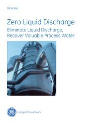
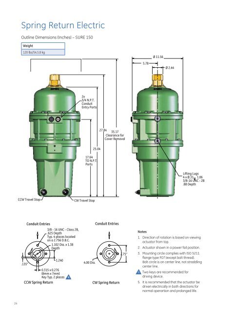
Spring Return Electric<br />
Outline Dimensions (Inches) – SURE 150<br />
Weight<br />
<strong>12</strong>0 lbs/54.5.8 kg<br />
5.78<br />
Ø 11.56<br />
Ø 2.44<br />
2x<br />
3/4 N.P.T.<br />
Conduit<br />
Entry Ports<br />
27.84<br />
35.17<br />
Clearance for<br />
Cover Removal<br />
25.04<br />
17.64<br />
TO N.P.T.<br />
Ports<br />
Lifting Lugs<br />
4 x Ø.31 1.06<br />
3/8-16 UNC - 2B<br />
.88 Depth<br />
CCW Travel Stop<br />
CW Travel Stop<br />
.135”<br />
Conduit Entries<br />
3/8 - 16 UNC - Class 2B,<br />
.625 Depth<br />
Typ. 4 places located<br />
on a 2.756 D.B.C.<br />
1.102 Dia. x 1.38<br />
Depth<br />
1.240<br />
0.315 x 0.276<br />
(8mm x 7mm)<br />
Key Typ. 2 places 4<br />
CCW Spring Return<br />
Conduit Entries<br />
2.75”<br />
4.00 Dia.<br />
CW Spring Return<br />
Notes<br />
1. Direction of rotation is based on viewing<br />
actuator from top.<br />
2. Actuator shown in a power fail position.<br />
3. Mounting circle complies with ISO 5211<br />
flange type F07 (except bolt thread).<br />
Bolt circle is on center line, not straddling<br />
center line.<br />
4. Two keys are recommended for<br />
driving device.<br />
5. It is recommended that the actuator be<br />
driven electrically in both directions for<br />
normal operartion and prolonged life.<br />
24