RCS Actuators brochure_3_12 / PDF 1436kb - GE Energy
RCS Actuators brochure_3_12 / PDF 1436kb - GE Energy
RCS Actuators brochure_3_12 / PDF 1436kb - GE Energy

You also want an ePaper? Increase the reach of your titles
YUMPU automatically turns print PDFs into web optimized ePapers that Google loves.
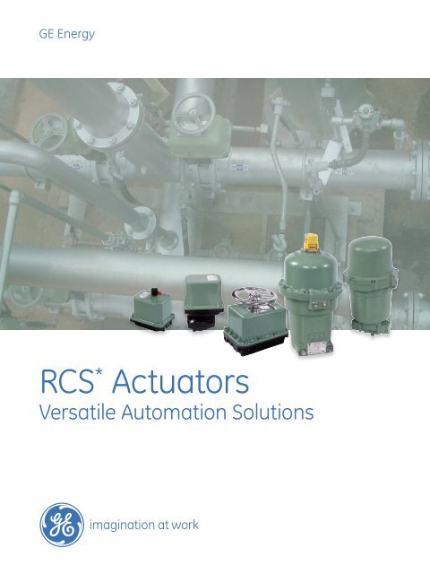
<strong>GE</strong> <strong>Energy</strong><br />
<strong>RCS</strong> * <strong>Actuators</strong><br />
Versatile Automation Solutions
Electric <strong>Actuators</strong><br />
Overview/Features & Benefits .......................................................................................................... 3-4<br />
MAR/DCR-10, 50 & 90 .......................................................................................................................... 5-7<br />
Outline Dimensions (MAR/DCR-10, 50 & 90) ........................................................................ 6<br />
Selection Charts ............................................................................................................................. 7-8<br />
MAR/DCR-100, <strong>12</strong>0, 160, 250, 800, 1600 & 4000.................................................................. 9-16<br />
Outline Dimensions (MAR/DCR-100, <strong>12</strong>0, 160 & 250) .................................................... 10<br />
Outline Dimensions (MAR/DCR-800)...................................................................................... 11<br />
Outline Dimensions (MAR 1600-70, 4000-<strong>12</strong>5, 4000-170) ................................... <strong>12</strong>-13<br />
Selection Charts ....................................................................................................................... 14-16<br />
SURE 24/25, 49, 100, 150 .............................................................................................................. 17-25<br />
Outline Dimensions (SURE 24/25) ........................................................................................... 18<br />
Outline Dimensions (SURE 49) .................................................................................................. 20<br />
Outline Dimensions (SURE 100) ................................................................................................ 22<br />
Outline Dimensions (SURE 150) ................................................................................................ 24<br />
Selection Charts .............................................................................................................................. 25<br />
CONTROLS<br />
EASC SCC-10 (Micro-Processor Based Analog Controller)............................................. 26-27<br />
DPC-100 & DPC-<strong>12</strong>0 (Profibus ® DP Actuator Controller) ....................................................... 28<br />
DNET115 (DeviceNet Actuator Controller) ............................................................................... 29<br />
ModBus Actuator Controller ............................................................................................................... 30<br />
2 2 | Dresser
<strong>RCS</strong> <strong>Actuators</strong> from <strong>GE</strong> <strong>Energy</strong>:<br />
Exceptional Automation Solutions<br />
<strong>RCS</strong> actuator products from <strong>GE</strong> <strong>Energy</strong> offer exceptional automation solutions for valve and<br />
equipment manufacturers and end users in the commercial, industrial, marine and power<br />
industries.<br />
Applicable to a myriad of automation solutions, from simple on/off control to heavy<br />
modulating, <strong>RCS</strong> actuators have been used in a variety of challenging, dirty and hazardous<br />
environments. <strong>GE</strong> specializes in offering engineered actuator solutions for your unique or<br />
unusual applications.<br />
Versatile, Advanced Technology Electric Rotary <strong>Actuators</strong><br />
Our electric rotary line offers a broad range of highly versatile actuator products. Targeted<br />
to 1/4 turn and multi-turn valves and dampers, <strong>RCS</strong> electric rotary actuators are also well<br />
suited for use in the automation of other types of rotating equipment.<br />
These rotary models span a torque range of <strong>12</strong>0 to 48,000 inch pounds with stroke speeds<br />
for 1/4 turn valves ranging from 0.5 seconds to 3 minutes and for multi-turn actuators from<br />
7.5 to 30 rpm.<br />
Cost-effective, Low-maintenance Spring Return <strong>Actuators</strong><br />
Our spring return electric rotary actuators employ torsion power springs that provide<br />
a reliable mechanical actuation solution for emergency shutoff or shutdown situations.<br />
This approach offers a cost-effective, low-maintenance and superior alternative to<br />
pneumatic, hydraulic, electrohydraulic or battery backup systems.<br />
The spring return electric rotary actuators have spring-ending torque to 1,800 inch pounds<br />
and are also available with speed options for simple on/off or modulating applications.<br />
Clockwise and counter-clockwise spring return options are available to drive any 1/4 turn<br />
device to a fail position upon loss of power.<br />
An Extensive Array of the Latest Control Solutions<br />
<strong>GE</strong> offers an extensive line of electrical and electronic accessories for <strong>RCS</strong> actuators,<br />
including the latest solutions to industry demands for analog control plus communication<br />
bus capabilities, including the protocols supported are Profibus * DP, DeviceNet * , and<br />
Modbus * .<br />
3
Features & Benefits<br />
Application Flexibility. <strong>RCS</strong> actuators from <strong>GE</strong> <strong>Energy</strong><br />
offers a broad and diverse range of speeds and<br />
available voltages. Coupled with an extensive line<br />
of control and communication accessories, these<br />
actuators offer both standard and unique solutions to<br />
a host of automation requirements. Standard operation<br />
for MAR and DCR models is part turn, reversible with<br />
unidirectional and multi-turn options available.<br />
Electric Motors. All <strong>RCS</strong> electric actuators are powered<br />
by an extended duty, high-torque, reversible motor.<br />
These motors are suitable for both on/off and modulating<br />
applications, with many models rated for extended<br />
duty. Each motor is Class “B” insulated and has an<br />
internal thermal overload protective device. This device<br />
protects the motor if a “stall” condition occurs thus<br />
preventing the motor from overheating which results in<br />
premature motor failure.<br />
Precision Gearing. All gears used in <strong>RCS</strong> actuators<br />
are manufactured from high alloy steel. Each gear is<br />
precision machined, then heat-treated, giving the gears<br />
exceptional strength. Each gear assembly is designed<br />
and tested to withstand the stall torque generated by<br />
the motor.<br />
Permanent Lubrication. Each gear and spring<br />
assembly is permanently lubricated with a high<br />
quality lubricant selected to meet a wide range of<br />
operational and environmental conditions. Periodic<br />
lubrication is not required.<br />
Versatile Installation. All <strong>RCS</strong> actuators can be<br />
installed and operated in any position. This allows<br />
flexibility for installation in confined locations or in<br />
retrofit applications.<br />
Manual Override. MAR/DCR10, 50 and 90 models<br />
feature a declutchable manual override. The actuator<br />
gearing is disengaged from the motor thus the<br />
actuator cannot be operated electrically while in<br />
manual operation. MAR100 through 4000 feature a<br />
manual override with an automatic electrical safety<br />
lockout switch. When the handwheel is engaged, the<br />
electrical switch isolates the motor from the supply<br />
voltage to prevent electrical operation.<br />
Environmental. With electroless nickel plated output<br />
shafts and stainless steel external bolting, <strong>RCS</strong> actuators<br />
will stand up to a broad range of environmental<br />
conditions. Optional marine epoxy paint systems or<br />
electroless nickel plated enclosures are also available<br />
to meet most onshore or offshore conditions.<br />
Standard Coating System. Electrostatically applied<br />
powder coating<br />
Optional Coating System. Ameron 2 part, water<br />
based epoxy, Sherwin Williams KEM Aqua °280 Water<br />
Reducible Enamel, or Electroless Nickel Plating<br />
Position Indication. Mechanical position indicators<br />
are standard on every model. These devices provide<br />
an external position reference for the actuator or<br />
driven equipment.<br />
Simple and Easy Wiring. Every actuator has a clearly<br />
marked and accessible terminal strip to provide for<br />
quick termination of field wiring.<br />
Accessories.<br />
■ Integral potentiometer<br />
■ Auxiliary limit switches<br />
■ Interposing relays<br />
■ Motor brakes<br />
■ D.C. analog position transmitter with integral<br />
power supply<br />
■ D.C. analog position (loop powered)<br />
■ D.C. analog position controller<br />
■ Digi-Tork bi-directional torque control<br />
■ Digi-Speed variable speed control<br />
■ Communication bus interface:<br />
- Profibus DP<br />
- DeviceNet <br />
- Modbus<br />
4
Part-Turn Electric | Multi-Turn Electric<br />
Optional 7” Handwheel Available<br />
NEMA 4 Enclosure<br />
Approvals<br />
MAR Models Only<br />
(Canadian Standard Association)<br />
CSA NRTL/C – Enclosure<br />
NEMA 7 Enclosure<br />
Approvals<br />
MAR Models Only<br />
(Canadian Standard Association)<br />
CSA NRTL/C Class I, Divisions 1 & 2,<br />
Groups C & D<br />
CSA NRTL/C Class II, Divisions 1 & 2,<br />
Groups E, F, & G<br />
CSA NRTL/C Approved to UL Standard No.<br />
429, Electrically Operated<br />
Values<br />
CSA NRTL/C Approved to UL Standard No.<br />
<strong>12</strong>03, Electrical Equipment for<br />
use in Explosion - proof<br />
And Dust - Ignition - proof<br />
Hazardous<br />
(Classified) Locations<br />
Models<br />
MAR10, 50, 90 – A.C. Supply<br />
DCR10, 50, 90 – D.C. Supply<br />
Typical Application<br />
For on/off and modulating control of:<br />
■ Part turn ball, butterfly or<br />
plug valves<br />
■ Rotary dampers<br />
■ Rotating equipment<br />
■ Multi-turn valve types<br />
Temperature Range<br />
Standard: -40°F to +150°F<br />
-40°C to +66°C<br />
Optional: -60°F to +<strong>12</strong>0°F<br />
-51°C to +49°C<br />
(Note: With Heaters Installed)<br />
Optional: Compliance to NFPA 130,<br />
capable of operation after exposure to<br />
ambient temperature of 482°F (250°C)<br />
for a minimum of 1 hour<br />
Voltage<br />
115 VAC, 1 Phase, 50/60 Hz.<br />
230 VAC, 1 Phase, 50/60 Hz.<br />
24 VAC, 1 Phase, 50/60 Hz.<br />
<strong>12</strong> VDC / 24 VDC<br />
Torque Range<br />
30 to 1,000 inch pounds<br />
(3.4 to 113.0 newton meters)<br />
Speed Range<br />
For 60 Hz. operation:<br />
.6 to 60 seconds for 90° revolution<br />
.3 and 30 RPM for multi-turns<br />
Standard Features<br />
AC Voltages<br />
2 – SPDT Switches, PTC Heater<br />
DC Voltages<br />
2 – SPDT (High Current) Switches<br />
Open/Close<br />
Modulating<br />
Multi-Turn<br />
5
Part-Turn Electric | Multi-Turn Electric<br />
Outline Dimensions (Inches) – MAR & DCR 10, 50, & 90<br />
Weight<br />
NEMA 4 Enclosure: <strong>12</strong> lbs./5.4 kg<br />
NEMA 7 Enclosure: 16 lbs./7.3 kg<br />
TOP<br />
8.00 Clearance required<br />
for cover removal<br />
9.81<br />
Mode<br />
One Only,<br />
3/4 N.P.T.<br />
Conduit<br />
Entrance<br />
7.41 NEMA 4<br />
7.81 NEMA 7<br />
9.41<br />
Electrical Mode<br />
3<br />
1.32<br />
0.954± .04<br />
3.00 0.828<br />
3.28<br />
6.00<br />
7.83<br />
Mounting Geometry - Bottom View<br />
5/16 - 18 UNC - Class 2B,<br />
.50 Depth<br />
Min. full thread<br />
Typ. 4 places<br />
2.25 Sq.<br />
0.875<br />
0.874 Dia.<br />
0.624 Across flats<br />
0.620<br />
Notes<br />
1. Direction of rotation is based on viewing actuator<br />
from top.<br />
2. Drawing shows output shaft in a fully clockwise<br />
(closed) position.<br />
3. Actuator shown with indicator in electrical mode.<br />
4. A NEMA 4 control enclosure is shown. Dimensions<br />
given are accurate for NEMA 7.<br />
1.<strong>12</strong>5 Typ.<br />
6
Part-Turn Electric | Multi-Turn Electric<br />
115 & 230 VAC, 1 Phase, 50/60 Hz.<br />
Model<br />
Output Torque<br />
Inch Pounds<br />
(N.m)<br />
Type<br />
MAR 10-.5MT 30 (3.4) Multi-Turn<br />
MAR 10-2 <strong>12</strong>0 (13.6) Part Turn<br />
MAR 10-2MT <strong>12</strong>0 (13.6) Multi-Turn<br />
MAR 10-10 350 (39.5) Part Turn<br />
MAR 10-30 425 (48.0) Part Turn<br />
MAR 10-60 400 (45.2) Part Turn<br />
MAR 50-.5MT 200 (22.6) Multi-Turn<br />
MAR 50-2 600 (67.8) Part Turn<br />
MAR 50-2MT 600 (67.8) Multi-Turn<br />
MAR 50-10 600 (67.8) Part Turn<br />
MAR 50-30 700 (79.1) Part Turn<br />
MAR 50-60 600 (67.8) Part Turn<br />
MAR 90-5 1,000 (113.0) Part Turn<br />
MAR 90-5MT 1,000 (113.0) Multi-Turn<br />
MAR 90-15 1,000 (113.0) Part Turn<br />
Speed of Operation<br />
60 Hz. (50 Hz.)<br />
30 RPM<br />
N/A<br />
2 second/90°<br />
(2.5 seconds/90°)<br />
7.5 RPM<br />
(6.2 RPM)<br />
10 seconds/90°<br />
(<strong>12</strong> seconds/90°)<br />
30 seconds/90°<br />
(35 seconds/90°)<br />
60 seconds/90°<br />
(70 seconds/90°)<br />
30 RPM<br />
N/A<br />
2 seconds/90°<br />
(2.5 seconds/90°)<br />
7.5 RPM<br />
(6.2 RPM)<br />
10 seconds/90°<br />
(<strong>12</strong> seconds/90°)<br />
30 seconds/90°<br />
(35 seconds/90°)<br />
60 seconds/90°<br />
(70 seconds/90°)<br />
5 seconds/90°<br />
(6 seconds/90°)<br />
3 RPM<br />
(2.5 RPM)<br />
15 seconds/90°<br />
(17.5 seconds/90°)<br />
Duty Cycle<br />
Rating<br />
115 Vac, 1Ph.,<br />
50/60 Hz.<br />
25%<br />
(2)<br />
50%<br />
(1)<br />
50%<br />
(2)<br />
50%<br />
(1)<br />
50%<br />
(2)<br />
50%<br />
(2)<br />
25%<br />
(2)<br />
40%<br />
(1)<br />
40%<br />
(2)<br />
50%<br />
(1)<br />
50%<br />
(2)<br />
50%<br />
(2)<br />
50%<br />
(1)<br />
50%<br />
(2)<br />
75%<br />
(2)<br />
Duty Cycle<br />
Rating<br />
230 Vac, 1Ph.,<br />
50/60 Hz.<br />
25%<br />
(2)<br />
50%<br />
(1)<br />
50%<br />
(2)<br />
50%<br />
(1)<br />
50%<br />
(2)<br />
50%<br />
(2)<br />
Current Ratings<br />
115 VAC<br />
Current Ratings<br />
230 VAC<br />
NLA* LRA* NLA* LRA*<br />
0.50 0.82 0.25 0.40<br />
0.40 0.60 0.30 0.40<br />
0.40 0.60 0.20 0.25<br />
0.40 0.60 0.20 0.25<br />
0.30 0.50 0.20 0.25<br />
0.35 0.55 0.20 0.25<br />
– 1.90 3.10 – –<br />
50%<br />
(1)<br />
50%<br />
(2)<br />
50%<br />
(1)<br />
50%<br />
(2)<br />
50%<br />
(2)<br />
50%<br />
(1)<br />
50%<br />
(2)<br />
50%<br />
(2)<br />
1.60 2.20 0.50 0.95<br />
1.60 2.20 0.50 0.95<br />
0.50 0.80 0.30 0.50<br />
0.35 0.55 0.20 0.25<br />
0.30 1.50 0.20 0.25<br />
0.55 1.55 0.25 0.85<br />
0.55 1.55 0.25 0.85<br />
0.50 0.60 0.20 0.35<br />
* (N.L.A.) — No Load Ampere (L.R.A.) — Locked Rotor Ampere (1) — Open/Close Service (2) — Open/Close or Modulating Service<br />
Duty Cycle<br />
The percentage of time the electric motor is energized vs. the time it is at rest, in reversing<br />
duty and with the actuator running at it’s rated load maximum published torque.<br />
Standard Modulating Duty Rating<br />
■ <strong>12</strong> motor starts (corrections) per minute<br />
■ At the rated duty cycle for that model<br />
■ With the speed of operation a minimum of 15 seconds for 90° or slower<br />
■ With positioning accuracy of (+/-) 1% of total span<br />
Isolation Relays<br />
To operate multiple actuators in parallel from a single signal requires isolating relays in the field wiring.<br />
Consult factory.<br />
Note — Multi-turn models are available with the following number of turns:<br />
1.4, 5, 8, 13, 18, 26 or 50. Must be specified when the order is placed.<br />
7
Part-Turn Electric | Multi-Turn Electric<br />
24 VAC<br />
Output Torque<br />
Inch Pounds (N.m)<br />
Speed of Operation<br />
60 Hz. (50 Hz.)<br />
Duty Cycle<br />
Rating<br />
24 VAC<br />
Current Ratings<br />
24 VAC<br />
Model<br />
Type<br />
NLA* LRA*<br />
MAR 10-2 <strong>12</strong>0 (13.6) Part Turn 2 seconds/90° 25% (1) 2.80 3.50<br />
MAR 10-2MT <strong>12</strong>0 (13.6) Multi-Turn 7.5 RPM 25% (1) 2.80 3.50<br />
MAR 10-10 350 (39.5) Part Turn 10 seconds/90° 25% (1) 1.90 2.70<br />
MAR 10-30 425 (48.0) Part Turn 30 seconds/90° 25% (1) 1.70 2.40<br />
MAR 10-60 400 (45.2) Part Turn 60 seconds/90° 25% (1) 1.80 2.50<br />
MAR 50-10 600 (67.8) Part Turn 10 seconds/90° 25% (1) 3.80 4.70<br />
MAR 50-30 700 (79.1) Part Turn 30 seconds/90° 25% (1) 1.90 2.70<br />
MAR 90-15 1,000 (113.0) Part Turn 15 seconds/90° 25% (1) 2.40 4.00<br />
<strong>12</strong> & 24 VDC<br />
Output Torque<br />
Inch Pounds (N.m)<br />
No Load<br />
Speed of Operation<br />
Duty Cycle<br />
Rating<br />
<strong>12</strong> VDC<br />
Duty Cycle<br />
Rating<br />
24 VDC<br />
Current Ratings<br />
<strong>12</strong> VAC<br />
Current Ratings<br />
24 VAC<br />
Model<br />
Type<br />
NLA* LRA* NLA* LRA*<br />
DCR 10-2 250 (28.2) Part Turn .6 seconds/90° 50% (1) 50% (1) 1.00 <strong>12</strong>.5 0.75 6.80<br />
DCR 10-2MT 250 (28.2) Multi-Turn 25 RPM 50% (2) 50% (2) 1.00 <strong>12</strong>.5 0.75 6.80<br />
DCR 10-10 400 (45.2) Part Turn 6.4 seconds/90° 50% (1) 50% (1) 0.19 3.90 0.08 2.10<br />
DCR 50-2 600 (67.8) Part Turn .7 seconds/90° 50% (1) 50% (1) 1.00 22.00 0.75 <strong>12</strong>.00<br />
DCR 50-2MT 600 (67.8) Multi-Turn 21 RPM 50% (2) 50% (2) 1.00 22.00 0.75 <strong>12</strong>.00<br />
DCR 50-10 600 (67.8) Part Turn 5.6 seconds/90° 50% (1) 50% (1) 0.90 5.80 0.5 2.40<br />
DCR 50-30 700 (79.1) Part Turn 21 seconds/90° 50% (2) 50% (2) 0.15 2.65 0.06 1.15<br />
DCR 90-5 900 (101.7) Part Turn 2.2 seconds/90° 50% (1) 50% (1) 1.00 <strong>12</strong>.50 0.75 6.80<br />
DCR 90-5MT 900 (101.7) Multi-Turn 7 RPM 50% (2) 50% (2) 1.00 <strong>12</strong>.50 0.75 6.80<br />
DCR 90-15 900 (101.7) Part Turn 5.6 seconds/90° 50% (2) 50% (2) 0.90 5.80 0.50 2.40<br />
* (N.L.A.) — No Load Ampere (L.R.A.) — Locked Rotor Ampere (1) — Open/Close Service (2) — Open/Close or Modulating Service<br />
Limit Switches (MAR Models)<br />
Standard: Two-single pole, double throw type (SPDT)<br />
with an option for 2 or 4 additional.<br />
Ratings: UL and CSA listed.<br />
15 amp & 1/2 H.P. at <strong>12</strong>5 or 250 VAC;<br />
1/2 amp at <strong>12</strong>5 VDC;<br />
1/4 amp at 250 VDC; 5 amp at <strong>12</strong>0 VAC<br />
Optional: All double pole, double throw type (DPDT).<br />
Ratings: UL and CSA listed.<br />
10 amp at <strong>12</strong>5/250 VAC (form ZZ);<br />
1/2 H.P. at <strong>12</strong>5 VDC; 3/4 H.P. at 250 VAC<br />
Limit Switches (DCR Models)<br />
Ratings: Ratings: UL and CSA listed.<br />
MIL-PRF-8805 Qualified Listing<br />
25 amp at 277 VAC; 1 H.P. at <strong>12</strong>5 VAC;<br />
2 H.P. at 250 VAC<br />
Isolation Relays<br />
To operate multiple actuators in parallel from a single<br />
signal requires isolating relays in the field wiring.<br />
Consult factory.<br />
Note — Multi-turn models are available with the<br />
following number of turns: 1.4, 5, 8, 13, 18, 26 or 50.<br />
Must be specified when the order is placed.<br />
8
Part-Turn Electric | Multi-Turn Electric<br />
NEMA 4 Enclosure<br />
Approvals<br />
MAR Models Only<br />
(Canadian Standard Association)<br />
CSA NRTL/C Type 4<br />
NEMA 4/6/7 Enclosure<br />
Approvals<br />
MAR Models Only<br />
(Canadian Standard Association)<br />
CSA NRTL/C Type 4 and 6<br />
CSA NRTL/C Class I, Divisions 1 & 2,<br />
Groups C & D<br />
CSA NRTL/C Class II, Divisions 1 & 2, Groups<br />
E, F & G<br />
CSA NRTL/C Approved to UL Standard No. 429,<br />
Electrically Operated Valves<br />
CSA NRTL/C Approved to UL Standard No.<br />
<strong>12</strong>03, Electrical Equipment for<br />
use in Explosion - proof<br />
And Dust - Ignition - proof<br />
Hazardous (Classified) Locations<br />
Models<br />
A.C. Voltage D.C. Voltage<br />
MAR100 DCR100<br />
MAR<strong>12</strong>0 DCR160<br />
MAR160 DCR250<br />
MAR250 DCR800<br />
MAR800<br />
Typical Application<br />
For on/off and modulating control of:<br />
■ Part turn ball, butterfly or plug<br />
valves<br />
■ Multi-turn valve types<br />
■ Rotary dampers<br />
■ Rotating equipment<br />
Temperature Range<br />
Standard: -40°F to +150°F<br />
-40°C to +66°C<br />
Optional: -60°F to +<strong>12</strong>0°F<br />
-51°C to +49°C<br />
(Note: With Heaters Installed)<br />
Optional: Compliance to NFPA 130,<br />
capable of operation after exposure<br />
to ambient temperature of 482°F<br />
(250°C) for a minimum of 1 hour<br />
Voltage<br />
115 VAC, 1 Phase, 50/60 Hz.<br />
230 VAC, 1 Phase, 50/60 Hz.<br />
24 VAC, 1 Phase, 50/60 Hz.<br />
220 VAC, 3 Phase, 60 Hz.<br />
440 VAC, 3 Phase 60 Hz.<br />
<strong>12</strong> VDC<br />
24 VDC<br />
Torque Range<br />
1,500 to 10,000 inch pounds<br />
(169.5 to 1<strong>12</strong>9.8 newton meters)<br />
Speed Range<br />
For 60 Hz. operation:<br />
1 .25 to 60 seconds for 90° revolution<br />
5 and <strong>12</strong> RPM for multi-turns<br />
Standard Features<br />
AC (Single and Three Phase ) Voltages<br />
4 – SPDT Switches, PTC Heater<br />
DC Voltages<br />
4 – SPDT (High Current) Switches<br />
9
Part-Turn Electric | Multi-Turn Electric<br />
Outline Dimensions (Inches) – MAR & DCR 100, <strong>12</strong>0, 160 & 250<br />
Weight<br />
NEMA 4 Enclosure: 34 lbs/15.45 kg<br />
NEMA 4/6/7 Enclosure: 44 lbs/20 kg<br />
9.00 Dia<br />
10.0 Clearance<br />
for cover removal<br />
Two 3/4<br />
N.P.T.<br />
Conduit<br />
Entrance<br />
2.14<br />
13.5 Max.<br />
10.5<br />
4<br />
2.69<br />
3.33<br />
<strong>12</strong>.36<br />
3.30<br />
1.<strong>12</strong>5<br />
1.<strong>12</strong>4 Dia.<br />
2.06<br />
1.05<br />
(Not to Scale)<br />
4.18<br />
8.36<br />
1.03<br />
Mounting Geometry<br />
3/8 - 16 UNC - Class 2B,<br />
0.75 Depth<br />
Typ. 4 places<br />
0.874<br />
0.870<br />
1.50 Typ.<br />
3.00 Sq. Typ.<br />
Notes<br />
1. Drawing shows the actuator output shaft in a fully<br />
clockwise (closed) position.<br />
2. Direction of actuator rotation is based on the top view<br />
from the handwheel.<br />
3. A NEMA 4 control cover is shown.<br />
Dimensions given are accurate for NEMA 4/6/7.<br />
4. Actuator is shown with handwheel in auto position.<br />
Height is 13.0” when manual override is used.<br />
10
Part-Turn Electric | Multi-Turn Electric<br />
Outline Dimensions (Inches) – MAR & DCR 800<br />
Weight<br />
NEMA 4 Enclosure: 34 lbs/15.4 kg<br />
NEMA 4/6/7 Enclosure: 44 lbs/20 kg<br />
9.00 Dia.<br />
10.0 Clearance<br />
for cover removal<br />
Two 3/4<br />
N.P.T.<br />
Conduit<br />
Entrance<br />
2.14<br />
10.8<br />
13.8 Max<br />
4<br />
3.31<br />
1.50<br />
1.35<br />
1.50<br />
3.33<br />
3.30<br />
1.501<br />
1.499<br />
2.06<br />
8.36<br />
4.18<br />
<strong>12</strong>.36<br />
Mounting Geometry<br />
1/2 - 13 UNC - Class 2B,<br />
0.88 Depth<br />
Typ. 4 places<br />
1.<strong>12</strong>4<br />
1.<strong>12</strong>0<br />
1.75 Typ.<br />
3.50 Sq. Typ.<br />
Notes<br />
1. Drawing shows the actuator output shaft in a fully<br />
clockwise (closed) position.<br />
2. Direction of actuator rotation is based on the top view<br />
from the handwheel.<br />
3. A NEMA 4 control cover is shown.<br />
Dimensions given are accurate for NEMA 4/6/7.<br />
4. Actuator is shown with handwheel in auto position.<br />
Height is 13.3” when manual override is used.<br />
11
Part-Turn Electric<br />
NEMA 4/6/7 Enclosure<br />
Approvals<br />
A.C. Models Only<br />
(Canadian Standard Association)<br />
CSA NRTL/C Type 4 and 6<br />
CSA NRTL/C Class I, Divisions 1 & 2, Groups<br />
C & D<br />
CSA NRTL/C Class II, Divisions 1 & 2,<br />
Groups E, F & G<br />
CSA NRTL/C Approved to UL Standard No.<br />
429, Electrically Operated<br />
Valves<br />
CSA NRTL/C Approved to UL Standard No.<br />
<strong>12</strong>03, Electrical Equipment for<br />
use in Explosion - proof<br />
And Dust - Ignition - proof<br />
Hazardous (Classified)<br />
Locations<br />
Models<br />
MAR 1600, MAR 4000<br />
Typical Application<br />
For on/off and modulating control of:<br />
■ Part turn ball, butterfly or plug<br />
valves<br />
■ Multi-turn valve types<br />
■ Rotary dampers<br />
■ Rotating equipment<br />
Temperature Range<br />
Standard: -40°F +150°F<br />
-40°C to +65°C<br />
Optional: -60°F to+150°F<br />
-50°C to +65°C<br />
Optional: Compliance to NFPA 130,<br />
capable of operation after exposure<br />
to ambient temperature of 482°F<br />
(250°C) for a minimum of 1 hour or a<br />
maximum of 3 hours.<br />
Voltage<br />
115 VAC, 1 Phase, 50/60 Hz.<br />
230 VAC, 1 Phase, 50/60 Hz.<br />
220 VAC, 3 Phase, 60 Hz.<br />
440 VAC, 3 Phase 60 Hz.<br />
Torque Range<br />
21,000 to 48,000 inch pounds<br />
(2,373 to 5,424 newton meters)<br />
Speed Range<br />
70 & 170 seconds for<br />
90° revolution<br />
Standard Features<br />
AC (Single or Three Phase) Voltages<br />
4 – SPDT Switches, PTC Heater<br />
<strong>12</strong>
Part-Turn Electric<br />
Outline Dimensions (Inches) – MAR 1600-70 and 4000-170<br />
Weight<br />
NEMA 4/6/7 Enclosure: <strong>12</strong>6 lbs/57.2 kg<br />
2<br />
21.0<br />
3.0<br />
3<br />
10.0 Clearance<br />
for cover removal<br />
3.0 REF<br />
4.37<br />
13.08<br />
<strong>12</strong>.36<br />
5.62<br />
Two 3/4<br />
N.P.T.<br />
Conduit<br />
Entrance<br />
4.56<br />
1.96<br />
6.42<br />
8.36<br />
Mounting Geometry<br />
5.00 Sq.<br />
1/2 x 1/4<br />
Keyslot, 2x<br />
Ø3.250<br />
x 3.75<br />
Notes<br />
1. Drawing shows the actuator output shaft in a fully<br />
clockwise (closed) position.<br />
2. Direction of actuator rotation is based on the top view<br />
of the eternal gearbox.<br />
3. Actuator is shown with handwheel in auto position.<br />
Height is 2.4” when manual override is used.<br />
3/4 – 10 UNC – Class 2B,<br />
.75 Depth, 4x<br />
13
Part-Turn Electric | Multi-Turn Electric<br />
115 & 230 VAC, 1 Phase, 50/60 Hz.<br />
Model<br />
Output<br />
Torque<br />
Inch Pounds<br />
(N.m)<br />
Type<br />
Speed of Operation<br />
60 Hz. (50 Hz.)<br />
Duty Cycle<br />
Rating<br />
115 Vac,<br />
1Ph.,<br />
50/60 Hz.<br />
Duty Cycle<br />
Rating<br />
230 Vac,<br />
1Ph., 50/60<br />
Hz.<br />
Current Ratings<br />
115 VAC<br />
Current Ratings<br />
230 VAC<br />
NLA* LRA* NLA* LRA*<br />
MAR 100-16 1,500 (169) Part Turn<br />
16 seconds/90°<br />
(19 seconds/90°)<br />
100%<br />
(2)<br />
50%<br />
(2)<br />
0.55 1.55 0.25 0.85<br />
MAR 100-30 1,800 (203) Part Turn<br />
30 seconds/90°<br />
(35 seconds/90°)<br />
100%<br />
(2)<br />
50%<br />
(2)<br />
0.50 0.60 0.30 0.35<br />
MAR 100-60 2500 (282) Part Turn<br />
60 seconds/90°<br />
(70 seconds/90°)<br />
100%<br />
(2)<br />
50%<br />
(2)<br />
0.35 0.55 0.20 0.35<br />
MAR <strong>12</strong>0-1.25 1,500 (169) Part Turn<br />
1.25 seconds/90°<br />
(2 seconds/90°)<br />
25%<br />
(1)<br />
25%<br />
(1)<br />
3.30 7.40 1.30 3.60<br />
MAR <strong>12</strong>0-1.25 MT 1,500 (169)<br />
Multi-<br />
Turn<br />
<strong>12</strong> RPM (10 RPM)<br />
25%<br />
(2)<br />
25%<br />
(2)<br />
3.30 7.40 1.30 3.60<br />
MAR 160-8 1,920 (217) Part Turn<br />
8 seconds/90°<br />
(9 seconds/90°)<br />
50%<br />
(1)<br />
50%<br />
(1)<br />
0.75 1.65 0.70 1.05<br />
MAR 160-16 2,000 (226) Part Turn<br />
16 seconds/90°<br />
(19 seconds/90°)<br />
75%<br />
(2)<br />
50%<br />
(2)<br />
0.60 1.60 0.35 0.90<br />
MAR 160-30 2,500 (282) Part Turn<br />
30 seconds/90°<br />
(35 seconds/90°)<br />
75%<br />
(2)<br />
50%<br />
(2)<br />
0.65 0.70 0.45 0.50<br />
MAR 160-60 2,800 (316) Part Turn<br />
60 seconds/90°<br />
(70 seconds/90°)<br />
100%<br />
(2)<br />
50%<br />
(2)<br />
0.50 0.60 0.30 0.35<br />
MAR 250-3 3,500 (395) Part Turn<br />
3 seconds/90°<br />
(4 seconds/90°)<br />
25%<br />
(1)<br />
50%<br />
(1)<br />
3.30 7.40 0.90 3.40<br />
MAR 250-3MT 3,500 (395)<br />
Multi-<br />
Turn<br />
5 RPM (4 RPM)<br />
25%<br />
(2)<br />
50%<br />
(2)<br />
3.30 7.40 0.90 3.40<br />
MAR 250-8 3,000 (339) Part Turn<br />
8 seconds/90°<br />
(9 seconds/90°)<br />
40%<br />
(1)<br />
50%<br />
(1)<br />
1.60 2.20 1.00 1.25<br />
MAR 250-16 4,000 (452) Part Turn<br />
16 seconds/90°<br />
(19 seconds/90°)<br />
50%<br />
(2)<br />
50%<br />
(2)<br />
1.10 1.80 0.70 1.05<br />
MAR 250-30 5,000 (565) Part Turn<br />
30 seconds/90°<br />
(35 seconds/90°)<br />
50%<br />
(2)<br />
50%<br />
(2)<br />
0.75 1.65 0.50 0.95<br />
MAR 250-60 5,000 (565) Part Turn<br />
60 seconds/90°<br />
(70 seconds/90°<br />
75%<br />
(2)<br />
50%<br />
(2)<br />
0.65 0.70 0.30 0.35<br />
MAR 800-<strong>12</strong> 7,500 (847) Part Turn<br />
<strong>12</strong> seconds/90°<br />
(14 seconds/90°)<br />
25%<br />
(1)<br />
25%<br />
(1)<br />
3.30 7.40 0.90 3.40<br />
MAR8 00-30<br />
10,000<br />
(1,130)<br />
Part Turn<br />
30 seconds/90°<br />
(35 seconds/90°)<br />
40%<br />
(2)<br />
50%<br />
(2)<br />
1.60 2.20 1.00 1.20<br />
MAR 800-60<br />
10,000<br />
(1,130)<br />
Part Turn<br />
60 seconds/90°<br />
(70 seconds/90°)<br />
75%<br />
(2)<br />
50%<br />
(2)<br />
0.55 1.55 0.50 0.95<br />
MAR 1600-70<br />
21,000<br />
(2,373)<br />
Part Turn<br />
70 seconds/90°<br />
(82 seconds/90°)<br />
25%<br />
(2)<br />
50%<br />
(2)<br />
3.30 7.40 0.90 3.40<br />
MAR 4000-170<br />
48,000<br />
(5,424)<br />
Part Turn<br />
170 seconds/90°<br />
(200 seconds/90°)<br />
25%<br />
(2)<br />
50%<br />
(2)<br />
3.30 7.40 0.90 3.40<br />
* (N.L.A.) — No Load Ampere (L.R.A.) — Locked Rotor Ampere (1) — Open/Close Service (2) — Open/Close or Modulating Service<br />
14<br />
Duty Cycle<br />
The percentage of time the electric motor is energized<br />
vs. the time it is at rest, in reversing duty and with the<br />
actuator running at it’s rated load maximum<br />
published torque.<br />
Standard Modulating Duty Rating<br />
■ <strong>12</strong> motor starts (corrections) per minute.<br />
■ At the rated duty cycle for that model<br />
■ With the speed of operation a minimum of 15<br />
seconds for 90° or slower<br />
■ With positioning accuracy of (+/-) 1% of total span<br />
Isolation Relays<br />
To operate multiple actuators in parallel from a single<br />
signal requires isolating relays in the field wiring.<br />
Consult factory.<br />
Note — Multi-turn models are available with the<br />
following number of turns: 1.4, 5, 8, 13, 18, 26 or 50.<br />
Must be specified when the order is placed.
Part-Turn Electric | Multi-Turn Electric<br />
<strong>12</strong> & 24 VDC<br />
Output Torque<br />
Inch Pounds (N.m)<br />
No Load<br />
Speed of Operation<br />
Duty Cycle Rating<br />
<strong>12</strong> VDC<br />
Duty Cycle<br />
Rating<br />
24 VDC<br />
Current Ratings<br />
<strong>12</strong> VAC<br />
Current Ratings<br />
24 VAC<br />
Model<br />
Type<br />
NLA* LRA* NLA* LRA*<br />
DCR 100-30 2,000 (225) Part Turn 11.5 seconds/90° 50% (2) 50% (2) 0.90 5.80 0.50 6.80<br />
DCR 160-16 2,200 (248) Part Turn 5.5 seconds/90° 50% (1) 50% (1) 1.00 <strong>12</strong>.50 0.75 6.80<br />
DCR 160-60 3,600 (406) Part Turn 22 seconds/90° 50% (2) 50% (2) 0.90 5.80 0.50 2.10<br />
DCR 250-8 3,000 (339) Part Turn 3.2 seconds/90° 50% (1) 50% (1) 1.00 22.00 0.75 <strong>12</strong>.00<br />
DCR 250-16 4,000 (452) Part Turn 5.7 seconds/90° 50% (1) 50% (1) 1.00 22.00 0.75 <strong>12</strong>.00<br />
DCR 250-30 5,000 (565) Part Turn 11.2 seconds/90° 50% (2) 50% (2) 1.00 <strong>12</strong>.50 0.75 2.40<br />
DCR 800-30 10,000 (1,130) Part Turn 13.3 seconds/90° 50% (2) 50% (2) 1.00 22.00 0.75 1.15<br />
DCR 800-60 10,000 (1,130) Part Turn 23 seconds/90° 50% (2) 50% (2) 1.00 <strong>12</strong>.50 0.75 1.15<br />
24 VAC<br />
Model<br />
Output Torque<br />
Inch Pounds (N.m)<br />
Type<br />
MAR 100-16 1,500 (169) Part Turn<br />
MAR 100-30 1,800 (203) Part Turn<br />
MAR 100-60 2,500 (282) Part Turn<br />
MAR 160-30 2,500 (282) Part Turn<br />
MAR 160-60 2,800 (316) Part-Turn<br />
MAR 250-60 5,000 (565) Part Turn<br />
Speed of Operation<br />
60 Hz. (50 Hz.)<br />
16 seconds/90°<br />
(19 seconds/90°)<br />
30 seconds/90°<br />
(35 seconds/90°)<br />
60 seconds/90°<br />
(70 seconds/90°)<br />
30 seconds/90°<br />
(35 seconds/90°)<br />
60 seconds/90°<br />
(70 seconds/90°)<br />
60 seconds/90°<br />
(70 seconds/90°)<br />
Duty Cycle<br />
Rating<br />
24 VAC<br />
Current Ratings<br />
24 VAC<br />
NLA*<br />
LRA*<br />
50% (2) 5.60 6.00<br />
75% (2) 2.40 4.50<br />
100% (2) 1.80 3.80<br />
75% (2) 4.50 5.00<br />
75% (2) 2.40 4.50<br />
50% (2) 4.50 5.00<br />
* (N.L.A.) — No Load Ampere (L.R.A.) — Locked Rotor Ampere (1) — Open/Close Service (2) — Open/Close or Modulating Service<br />
Limit Switches (MAR Models)<br />
Standard: Four-single pole, double throw type<br />
(SPDT) with an option for 2 additional.<br />
Ratings: UL and CSA listed.<br />
15 amp & 1/2 H.P. at <strong>12</strong>5 or 250 VAC<br />
1/2 amp at <strong>12</strong>5 VDC;<br />
1/4 amp at 250 VDC<br />
Lamp Load: 5 amp at <strong>12</strong>0 VAC<br />
Optional: All double pole, double throw type (DPDT).<br />
Ratings: UL and CSA listed.<br />
10 amp at <strong>12</strong>5/250 VAC (form ZZ);<br />
1/2 H.P. at <strong>12</strong>5 VDC; 3/4 H.P. at<br />
250 VAC<br />
Limit Switches (DCR Models)<br />
Ratings: Ratings: UL and CSA listed.<br />
MIL-PRF-8805 Qualified Listing<br />
25 amp at 277 VAC; 1 H.P. at <strong>12</strong>5 VAC;<br />
2 H.P. at 250 VAC<br />
Isolation Relays<br />
To operate multiple actuators in parallel from a single<br />
signal requires isolating relays in the field wiring.<br />
Consult factory.<br />
Heater<br />
PTC (Positive Temperature Coefficient)<br />
Heater standard in an AC Voltage Models<br />
15
Part-Turn Electric | Multi-Turn Electric<br />
220 & 440 VAC, 3 Phase, 60 Hz.<br />
Model<br />
Output Torque<br />
Inch Pounds (N.m)<br />
Type<br />
MAR 100-16 1,500 (169) Part Turn<br />
MAR <strong>12</strong>0-1.25 1,500 (169) Part Turn<br />
MAR <strong>12</strong>0-1.25<br />
MT<br />
Speed of Operation<br />
60 Hz. (50 Hz.)<br />
16 seconds/90°<br />
(19 seconds/90°)<br />
1.25 seconds/90°<br />
(2 seconds/90°)<br />
Duty Cycle Rating<br />
220 Vac, 3Ph.,<br />
60 Hz.<br />
Duty Cycle Rating<br />
440 Vac, 3Ph.,<br />
60 Hz.<br />
Current Ratings<br />
220 VAC<br />
Current Ratings<br />
440 VAC<br />
NLA* LRA* NLA* LRA*<br />
25% 25% 0.34 1.20 0.15 0.75<br />
25% 25% 1.60 3.50 0.82 1.80<br />
1,500 (169) Multi-Turn <strong>12</strong> RPM (10 RPM) 25% 25% 1.60 3.50 0.82 1.80<br />
MAR 160-8 1,920 (217) Part Turn<br />
MAR 160-16 2,000 (226) Part Turn<br />
8 seconds/90°<br />
(9 seconds/90°)<br />
16 seconds/90°<br />
(19 seconds/90°)<br />
25% 25% 0.34 1.20 0.15 0.75<br />
25% 25% 0.34 1.20 0.15 0.75<br />
MAR 250-3 3,500 (316) Part Turn<br />
3 seconds/90°<br />
(4 seconds/90°)<br />
25% 25% 1.60 3.50 0.82 1.80<br />
MAR 250-3MT 3,500 (316) Multi-Turn 5 RPM (4 RPM) 25% 25% 1.60 3.50 0.82 1.80<br />
MAR 250-16 4,000 (452) Part Turn<br />
MAR 250-30 5,000 (565) Part Turn<br />
MAR 250-60 5,000 (565) Part Turn<br />
MAR 800-<strong>12</strong> 7,500 (847) Part Turn<br />
MAR 800-30 10,000 (1,130) Part Turn<br />
MAR 800-60 10,000 (1,130) Part Turn<br />
MAR 1600-70 21,000 (2,373) Part Turn<br />
MAR 4000-170 48,000 (5,424) Part Turn<br />
16 seconds/90°<br />
(19 seconds/90°)<br />
30 seconds/90°<br />
(35 seconds/90°)<br />
60 seconds/90°<br />
(70 seconds/90°)<br />
<strong>12</strong> seconds/90°<br />
(14 seconds/90°)<br />
30 seconds/90°<br />
(35 seconds/90°)<br />
60 seconds/90°<br />
(70 seconds/90°)<br />
70 seconds/90°<br />
(80 seconds/90°)<br />
170 seconds/90°<br />
(200 seconds/90°)<br />
25% 25% 0.34 1.20 0.15 0.75<br />
25% 25% 0.34 1.20 0.15 0.75<br />
25% 25% 0.34 1.20 0.15 0.75<br />
25% 25% 1.60 3.50 0.82 1.80<br />
25% 25% 0.34 1.20 0.15 0.75<br />
25% 25% 0.34 1.20 0.15 0.75<br />
25% 25% 1.60 3.50 0.82 1.80<br />
25% 25% 1.60 3.50 0.82 1.80<br />
NOTE — Multi-turn models are available with the following number of turns: 1.4, 5, 8, 13, 18, 26 or 50. Must be specified when the order is placed.<br />
* (N.L.A.) — No Load Ampere (L.R.A.) — Locked Rotor Ampere (1) — Open/Close Service (2) — Open/Close or Modulating Service<br />
Duty Cycle<br />
The percentage of time the electric motor is energized<br />
vs. the time it is at rest, in reversing duty and with the<br />
actuator running at it’s rated load maximum<br />
published torque.<br />
Standard Modulating Duty Rating<br />
■ <strong>12</strong> motor starts (corrections) per minute<br />
■ At the rated duty cycle for that model<br />
■ With the speed of operation a minimum of 15<br />
seconds for 90° or slower<br />
■ With positioning accuracy of (+/-) 1% of total span<br />
Isolation Relays<br />
To operate multiple actuators in parallel from a single<br />
signal requires isolating relays in the field wiring.<br />
Consult factory.<br />
Note — Multi-turn models are available with the<br />
following number of turns: 1.4, 5, 8, 13, 18, 26 or 50.<br />
Must be specified when the order is placed.<br />
16
Spring Return Electric<br />
Optional Manual Override Available<br />
NEMA 4 Enclosure<br />
A.C. Models Only<br />
(Canadian Standard Association)<br />
CSA NRTL/C Type 4<br />
NEMA 7 Enclosure<br />
A.C. Models Only<br />
(Canadian Standard Association)<br />
CSA NRTL/C Class I, Divisions 1 & 2,<br />
Groups C & D<br />
CSA NRTL/C Class II, Divisions 1 & 2,<br />
Groups E, F, & G<br />
CSA NRTL/C Approved to UL Standard No.<br />
429, Electrically Operated Values<br />
CSA NRTL/C Approved to UL Standard No.<br />
<strong>12</strong>03, Electrical Equipment for<br />
use in Explosion - proof<br />
And Dust - Ignition - proof<br />
Hazardous (Classified) Locations<br />
Models<br />
SURE 24, SURE 25<br />
Typical Application<br />
For on/off and modulating<br />
control of:<br />
■ Part turn ball, butterfly,<br />
plug valves or rotary<br />
dampers when emergency<br />
shutdown or shutoff<br />
capability is required in the<br />
event of a loss of power.<br />
Temperature Range<br />
Standard: -40°F to +150°F<br />
-40°C to +65°C<br />
Optional: -60°F to +150°F<br />
-50°C to +65°C<br />
Optional: Compliance to NFPA<br />
130, capable of operation<br />
after exposure to ambient<br />
temperature of 482°F (250°C)<br />
for a minimum of 1 hour<br />
Voltage<br />
115 VAC, 1 Phase, 50/60 Hz.<br />
230 VAC, 1 Phase, 50/60 Hz.<br />
Torque Range<br />
300 pound inches spring end (34<br />
newton meters)<br />
Speed Range<br />
5 & 10 seconds for<br />
90° revolution, motor operation<br />
2 to 5 seconds spring operation<br />
Spring<br />
Flat, spring steel torsion spring,<br />
XYLAN ® coated<br />
Standard Features<br />
AC Voltages<br />
2 – SPDT Switches,<br />
PTC Heater, Motor Break<br />
SURE 24<br />
SURE 25<br />
17
Spring Return Electric<br />
Outline Dimensions (Inches) – SURE 24/25<br />
Weight<br />
23 lbs/10.4 kg<br />
5.0 Clearance for<br />
cover removal<br />
TOP<br />
10.54 NEMA 4<br />
10.95 NEMA 7<br />
5<br />
One Only<br />
3/4 N.P.T.<br />
Conduit<br />
Entrance<br />
4.50<br />
.953 ± .043<br />
7.83<br />
3.28<br />
CCW spring return,<br />
adjustable stop<br />
for end of travel<br />
6.00<br />
3.00<br />
CW spring return,<br />
adjustable stop<br />
for end of travel<br />
Mounting Geometry - Bottom View<br />
5/16 - 18 UNC - Class 2B,<br />
.375 Depth<br />
Min, full thread<br />
Typ. 4 places<br />
2.25 Sq.<br />
1.<strong>12</strong>5 Typ.<br />
0.875<br />
0.873 Dia.<br />
0.624<br />
0.620<br />
Across flats<br />
Notes<br />
1. Direction of rotation is based on viewing actuator<br />
from top.<br />
2. Drawing shows actuator output shaft in power fail<br />
clockwise position.<br />
3. Standard unit fails clockwise (closed).<br />
4. Optional unit fails counter-clockwise (open).<br />
5. NEMA 4 cover shown.<br />
Dimensions given are accurate for NEMA 7.<br />
18
Spring Return Electric<br />
Not Available with Manual Override<br />
NEMA 4/6/7 Enclosure<br />
Approvals<br />
A.C. Models Only<br />
(Canadian Standard Association)<br />
CSA NRTL/C Type 4 and 6<br />
CSA NRTL/C Class I, Divisions 1 & 2,<br />
Groups C & D<br />
CSA NRTL/C Class II, Divisions 1 & 2,<br />
Groups E, F & G<br />
CSA NRTL/C Approved to UL Standard No.<br />
429, Electrically Operated Valves<br />
CSA NRTL/C Approved to UL Standard No.<br />
<strong>12</strong>03, Electrical Equipment for<br />
use in Explosion - proof<br />
And Dust - Ignition - proof<br />
Hazardous (Classified) Locations<br />
Models<br />
SURE 49<br />
Typical Application<br />
For on/off and modulating<br />
control of:<br />
■ Part turn ball, butterfly,<br />
plug valves or rotary<br />
dampers when<br />
emergency shutdown<br />
or shutoff capability is<br />
required in the event of a<br />
loss of power<br />
Temperature Range<br />
Standard: -40°F to +150°F<br />
-40°C to +65°C<br />
Optional: -60°F to +150°F<br />
-50°C to +65°C<br />
Optional: Compliance to NFPA<br />
130, capable of operation<br />
after exposure to ambient<br />
temperature of 482°F (250°C)<br />
for a minimum of 1 hour<br />
Voltage<br />
115 VAC, 1 Phase, 50/60 Hz.<br />
230 VAC, 1 Phase, 50/60 Hz.<br />
24 VAC, 1 Phase, 50/60 Hz.<br />
<strong>12</strong> VDC, 24 VDC<br />
Torque Range<br />
600 pound inches spring end<br />
(68 newton meters)<br />
Speed Range<br />
5 , 15 & 30 seconds for<br />
90° revolution, motor<br />
operation<br />
2 to 5 seconds spring<br />
operation<br />
Spring<br />
Helical torsion spring, spring<br />
steel XYLAN ® coated<br />
Standard Features<br />
AC Voltages<br />
4 – SPDT Switches, PTC<br />
Heater, Motor Break<br />
DC Voltages<br />
2 – SPDT (High Current)<br />
Switches, PTC Heater,<br />
Motor Break<br />
19
Spring Return Electric<br />
Outline Dimensions (Inches) – SURE 49<br />
Weight<br />
NEMA 4/6/7 Enclosure: 49 lbs/22.2 kg<br />
9.62 as shown<br />
(10.22 Max.)<br />
5.0 Clearance for cover<br />
removal<br />
TOP<br />
Control cover<br />
4.81<br />
18.15<br />
One Only<br />
3/4 N.P.T.<br />
Conduit<br />
Entrance<br />
9.93<br />
0.33<br />
Spring housing<br />
Shock absorber<br />
2.51<br />
.86<br />
1.03<br />
1.15<br />
3.56<br />
7.<strong>12</strong><br />
2.00 Pilot Dia.<br />
Mounting Geometry - Bottom View<br />
2.25 Sq.<br />
1.<strong>12</strong>5 Typ.<br />
.625<br />
.621<br />
Across flats<br />
.875<br />
.874<br />
5/16 - 18 UNC - Class 2B,<br />
.63 Depth<br />
Typ. 4 places<br />
Notes<br />
1. Direction of rotation is based on viewing<br />
actuator from top.<br />
2. Actuator shown in energized position.<br />
3. It is recommended that the actuator be<br />
driven electrically in both directions for<br />
normal operartion and prolonged life.<br />
20
Spring Return Electric<br />
Optional Manual Override Available<br />
NEMA 4/6/7 Enclosure<br />
Approvals<br />
A.C. Models Only<br />
(Canadian Standard Association)<br />
CSA NRTL/C Type 4<br />
CSA NRTL/C Class I, Divisions 1 & 2, Groups<br />
C & D<br />
CSA NRTL/C Class II, Divisions 1 & 2,<br />
Groups E, F & G<br />
CSA NRTL/C Approved to UL Standard No.<br />
429, Electrically Operated<br />
Valves<br />
CSA NRTL/C Approved to UL Standard No.<br />
<strong>12</strong>03, Electrical Equipment for<br />
use in Explosion - proof<br />
And Dust - Ignition - proof<br />
Hazardous (Classified)<br />
Locations<br />
Models<br />
SURE 100<br />
Typical Application<br />
For on/off and modulating<br />
control of:<br />
■ Part turn ball, butterfly,<br />
plug valves or rotary<br />
dampers when emergency<br />
shutdown<br />
or shutoff capability is<br />
required in the event of a<br />
loss of power<br />
Temperature Range<br />
Standard: -40°F to +150°F<br />
-40°C to +65°C<br />
Optional: -60°F to +150°F<br />
-50°C to +65°C<br />
Optional: Compliance to NFPA<br />
130, capable of operation<br />
after exposure to ambient<br />
temperature of 482°F (250°C)<br />
for a minimum of 1 hour<br />
Voltage<br />
115 VAC, 1 Phase, 50/60 Hz.<br />
230 VAC, 1 Phase, 50/60 Hz.<br />
Torque Range<br />
<strong>12</strong>00 pound inches spring end<br />
(136 newton meters)<br />
Speed Range<br />
10 & 30 seconds for<br />
90° revolution, motor operation<br />
5 to 7 seconds spring operation<br />
Spring<br />
Helical torsion spring, spring<br />
steel, XYLAN ® coated<br />
Standard Features<br />
AC Voltages<br />
4 – SPDT Switches, PTC<br />
Heater, Motor Break<br />
21
Spring Return Electric<br />
Outline Dimensions (Inches) – SURE 100<br />
Weight<br />
NEMA 4/6/7 Enclosure: 70 lbs/31.8 kg<br />
11.56 Dia.<br />
2.34<br />
Dia.<br />
5.78<br />
Indicator<br />
Cover<br />
21.53<br />
28.81<br />
Cover removal<br />
18.6<br />
One Only<br />
3/4 N.P.T.<br />
Conduit<br />
Entrance<br />
10.87<br />
CCW spring drive<br />
adjustable end of<br />
travel stop<br />
CW spring drive<br />
adjustable end of<br />
travel stop<br />
Spring<br />
housing<br />
Valve mounting<br />
surface<br />
Conduit Entries<br />
Conduit Entries<br />
5/16 - 18 UNC - Class 2B, .63<br />
Depth<br />
Typ. 4 places located on a<br />
2.756 D.B.C.<br />
1.102 Dia. x 1.38 DP.<br />
1.240<br />
4.00 Dia.<br />
.135”<br />
0.315 x 0.276 (8mm x 7mm)<br />
Key Typ. 2 places<br />
4<br />
CCW Spring Return<br />
CW Spring Return<br />
2.75”<br />
Notes<br />
1. Direction of rotation is based on viewing actuator<br />
from top.<br />
2. Actuator shown in a power fail position.<br />
3. Mounting circle complies with ISO 5211 flange type<br />
F07 (except bolt thread). Bolt circle is on center line,<br />
not straddling center line.<br />
4. Two keys are recommended for driving device.<br />
5. It is recommended that the actuator be<br />
driven electrically in both directions for<br />
normal operartion and prolonged life.<br />
22
Spring Return Electric<br />
Optional Manual Override Available<br />
NEMA 4/6/7 Enclosure<br />
Approvals<br />
A.C. Models Only<br />
(Canadian Standard Association) - pending<br />
CSA NRTL/C Type<br />
CSA NRTL/C Class I, Divisions 1 & 2, Groups<br />
C & D<br />
CSA NRTL/C Class II, Divisions 1 & 2,<br />
Groups E, F & G<br />
CSA NRTL/C Approved to UL Standard No.<br />
429, Electrically Operated<br />
Valves<br />
CSA NRTL/C Approved to UL Standard No.<br />
<strong>12</strong>03, Electrical Equipment for<br />
use in Explosion - proof<br />
And Dust - Ignition - proof<br />
Hazardous (Classified)<br />
Locations<br />
Models<br />
SURE 150<br />
Typical Application<br />
For on/off and modulating<br />
control of:<br />
■ Part turn ball, butterfly,<br />
plug valves or rotary<br />
dampers when<br />
emergency shutdown<br />
or shutoff capability is<br />
required in the event of a<br />
loss of power<br />
Temperature Range<br />
Standard: -40°F to +150°F<br />
-40°C to +65°C<br />
Optional: -60°F to +150°F<br />
-50°C to +65°C<br />
Optional: Compliance<br />
to NFPA 130, capable of<br />
operation after exposure<br />
to ambient temperature of<br />
482°F (250°C) for a minimum<br />
of 1 hour<br />
Voltage<br />
115 VAC, 1 Phase, 50/60 Hz.<br />
230 VAC, 1 Phase, 50/60 Hz.<br />
Torque Range<br />
1800 pound inches<br />
spring end<br />
(204 newton meters)<br />
Speed Range<br />
15 seconds for 90° revolution,<br />
motor operation<br />
5 seconds spring operation<br />
Spring<br />
Helical torsion spring, spring<br />
steel, XYLAN ® coated<br />
Standard Features<br />
AC Voltages<br />
4 – SPDT Switches, PTC<br />
Heater, Motor Break<br />
23
Spring Return Electric<br />
Outline Dimensions (Inches) – SURE 150<br />
Weight<br />
<strong>12</strong>0 lbs/54.5.8 kg<br />
5.78<br />
Ø 11.56<br />
Ø 2.44<br />
2x<br />
3/4 N.P.T.<br />
Conduit<br />
Entry Ports<br />
27.84<br />
35.17<br />
Clearance for<br />
Cover Removal<br />
25.04<br />
17.64<br />
TO N.P.T.<br />
Ports<br />
Lifting Lugs<br />
4 x Ø.31 1.06<br />
3/8-16 UNC - 2B<br />
.88 Depth<br />
CCW Travel Stop<br />
CW Travel Stop<br />
.135”<br />
Conduit Entries<br />
3/8 - 16 UNC - Class 2B,<br />
.625 Depth<br />
Typ. 4 places located<br />
on a 2.756 D.B.C.<br />
1.102 Dia. x 1.38<br />
Depth<br />
1.240<br />
0.315 x 0.276<br />
(8mm x 7mm)<br />
Key Typ. 2 places 4<br />
CCW Spring Return<br />
Conduit Entries<br />
2.75”<br />
4.00 Dia.<br />
CW Spring Return<br />
Notes<br />
1. Direction of rotation is based on viewing<br />
actuator from top.<br />
2. Actuator shown in a power fail position.<br />
3. Mounting circle complies with ISO 5211<br />
flange type F07 (except bolt thread).<br />
Bolt circle is on center line, not straddling<br />
center line.<br />
4. Two keys are recommended for<br />
driving device.<br />
5. It is recommended that the actuator be<br />
driven electrically in both directions for<br />
normal operartion and prolonged life.<br />
24
Spring Return Electric<br />
115 & 230 VAC, 1 Phase, 50/60 Hz.<br />
Model<br />
Output Torque<br />
Inch Pounds (N.m)<br />
Electrical Speed<br />
of Operation<br />
60 Hz. (50 Hz.)<br />
Speed of Operation<br />
60 Hz. (50 Hz.)<br />
Duty Cycle<br />
Rating<br />
115 VAC<br />
Duty Cycle<br />
Rating<br />
220 VAC<br />
Current Ratings<br />
115 VAC<br />
Current Ratings<br />
220 VAC<br />
NLA* LRA* NLA* LRA*<br />
Sure 25-5 300 (34)<br />
5 seconds/90°<br />
(6 seconds/90°)<br />
2 seconds/90°<br />
50%<br />
(1)<br />
50%<br />
(1)<br />
1.40 2.15 CF** CF**<br />
Sure 25-10 300 (34)<br />
10 seconds/90°<br />
(<strong>12</strong> seconds/90°)<br />
2 seconds/90°<br />
50%<br />
(2)<br />
50%<br />
(2)<br />
1.00 1.55 CF** CF**<br />
Sure 24-10 300 (34)<br />
10 seconds/90°<br />
(<strong>12</strong> seconds/90°)<br />
2 seconds/90°<br />
25%<br />
(1)<br />
25%<br />
(1)<br />
0.70 1.05 0.45 65%<br />
Sure 49-5 600 (68)<br />
5 seconds/90°<br />
(6 seconds/90°)<br />
2 seconds/90°<br />
25%<br />
(1)<br />
25%<br />
(1)<br />
1.10 1.80 1.00 1.20<br />
Sure 49-15 600 (68)<br />
15 seconds/90°<br />
(18 seconds/90°)<br />
2 seconds/90°<br />
25%<br />
(1)<br />
25%<br />
(1)<br />
0.55 1.55 0.35 0.90<br />
Sure 49-30 600 (68)<br />
30 seconds/90°<br />
(35 seconds/90°)<br />
2 seconds/90°<br />
50%<br />
(2)<br />
50%<br />
(2)<br />
0.65 0.70 0.30 0.35<br />
Sure 100-10 1,200 (136)<br />
10 seconds/90°<br />
(<strong>12</strong> seconds/90°)<br />
5 seconds/90°<br />
(max) +<br />
25%<br />
(1)<br />
25%<br />
(1)<br />
1.90 2.90 0.90 1.35<br />
Sure 100-30 1,200 (136)<br />
30 seconds/90°<br />
(35 seconds/90°)<br />
7 seconds/90°<br />
(max ) +<br />
50%<br />
(2)<br />
50%<br />
(2)<br />
0.65 0.95 0.35 0.45<br />
Sure 150-15 1,800 (136)<br />
15 seconds/90°<br />
(18 seconds/90°)<br />
5 seconds/90°<br />
(max) +<br />
25%<br />
(1), (2)<br />
25%<br />
(1), (2)<br />
1.90 2.90 0.90 1.35<br />
24 VAC<br />
Model<br />
Output Torque<br />
Inch Pounds (N.m)<br />
Electrical Speed<br />
of Operation<br />
60 Hz. (50 Hz.)<br />
Speed of Operation<br />
60 Hz. (50 Hz.)<br />
Duty Cycle Rating<br />
115 VAC<br />
Current Ratings<br />
115 VAC<br />
NLA*<br />
LRA*<br />
Sure 49-30 600 (68)<br />
30 seconds/90°<br />
(35 seconds/90°)<br />
2 seconds/90°<br />
25%<br />
(2)<br />
4.50 5.00<br />
<strong>12</strong> & 24 VDC<br />
Model<br />
Output Torque<br />
Inch Pounds (N.m)<br />
Electrical Speed<br />
of Operation<br />
Speed of<br />
Operation<br />
Duty Cycle Rating<br />
<strong>12</strong> VDC<br />
Duty Cycle Rating<br />
24 VDC<br />
Current Ratings<br />
<strong>12</strong> VDC<br />
Current Ratings<br />
24 VDC<br />
NLA* LRA* NLA* LRA*<br />
Sure 49-5 600 (68) 5 seconds/90°<br />
2 seconds/90°<br />
(1)<br />
50%<br />
(1)<br />
50% 1.00 22.00 1.00 <strong>12</strong>.30<br />
* (N.L.A.) — No Load Ampere (L.R.A.) — Locked Rotor Ampere (1) — Open/Close Service (2) — Open/Close or Modulating Service<br />
** (CF) — Consult Factory + — Approximate, Based on Load<br />
Limit Switches (Sure 24 & 25)<br />
Standard: Two-single pole, double throw<br />
type (SPDT) with an option for 2 or 4<br />
additional.<br />
Ratings: UL and CSA listed.<br />
MIL-PRF-8805 Qualified Listing<br />
25 amp at 277 VAC; 1 H.P. at<br />
<strong>12</strong>5 VAC; 2 H.P. at 250 VAC<br />
Isolation Relays<br />
To operate multiple actuators in parallel<br />
from a single signal requires isolating<br />
relays in the field wiring.<br />
Consult factory.<br />
Limit Switches (Sure 49, 100 7 150)<br />
Standard: Four-single pole, double throw<br />
type (SPDT) with an option for 2 additional.<br />
Ratings: Ratings: UL and CSA listed.<br />
15 amp & 1/2 H.P. at <strong>12</strong>5 or<br />
250 VAC<br />
1/2 amp at <strong>12</strong>5 VDC; 1/4 amp<br />
at 250 VDC<br />
Lamp Load: 5 amp at <strong>12</strong>0 VAC<br />
Optional: All double pole, double throw<br />
type (DPDT).<br />
Ratings: Ratings: UL and CSA listed.<br />
10 amp at <strong>12</strong>5 or 250 VAC (form ZZ)<br />
1/2 H.P. at <strong>12</strong>5 VDC; 3/4 H.P. at<br />
250 VDC<br />
Heater<br />
PTC (Positive Temperature Coefficient)<br />
Heater standard in an AC Voltage Models<br />
Duty Cycle<br />
The percentage of time the electric<br />
motor is energized vs. the time it is<br />
at rest, in reversing duty and with<br />
the actuator running at it’s rated<br />
load - maximum published torque.<br />
Standard Modulating Duty Rating<br />
■ <strong>12</strong> motor starts (corrections)<br />
per minute.<br />
■ At the rated duty cycle for<br />
that model.<br />
■ With the speed of operation a<br />
minimum of 15 seconds for<br />
90° or slower.<br />
■ With positioning accuracy of<br />
(+/-) 1% of total span.<br />
25
D.C. Analog - EASC SCC-05<br />
Specifications<br />
Power Requirements<br />
Model SCC05-115/230 A:<br />
Single phase, 115 or 230 VAC 50/60 Hz. (Jumper selectable)<br />
Input Command Signal<br />
Menu selectable factory defaults:<br />
— 4-20 mADC<br />
— 1 -5 VDC<br />
— 2-10 VDC<br />
— 0-10 VDC<br />
Infinite adjustment during System<br />
Application<br />
The SCC-05 EASC (Electric Actuator Smart Controller) card is a costeffective<br />
means for accurate and precise positioning control of <strong>RCS</strong><br />
actuators utilizing an analog input signal. The EASC “One-Switch” setup<br />
system eliminates the need for external meters, dip switches, trimming<br />
potentiometers, or a display screen on the module. Simply set the full<br />
open and full closed positions, and the microprocessor technology<br />
does the rest. For control applications requiring an input-only control<br />
requirement, the SCC-05 provides excellent performance and a variety<br />
of standard features suitable for today’s challenging automation and<br />
control requirements.<br />
Features<br />
Mounts internally in <strong>RCS</strong> actuator models: MAR-10, MAR-50, MAR-90,<br />
MAR-100, MAR-160, MAR-250, MAR-800 & all SurePowr models.<br />
■ Simple single switch setup allows complete control of controller<br />
configuration<br />
■ One step selection of input/output ranges including 4-20 mAdc, 1-5<br />
Vdc, 2-10 Vdc and 0-10 Vdc, or virtually any custom range required<br />
■ “Learns while it runs” tuning makes configuration simple<br />
■ Selectable fail options<br />
■ Intelligent positioning reduces motor cycling, increases motor life<br />
and extends the actuator duty<br />
■ Optional Modbus RTU remote control over a RS-485 network.<br />
Complete access to all controller functions from your factory<br />
automation system<br />
■ Quick disconnect terminal strips facilitate fast and easy actuator<br />
maintenance and troubleshooting<br />
■ Always wires the same; no need to determine rotation direction<br />
during installation; rotation is selected at setup<br />
■ Robust power switching components, designed specifically for<br />
actuator motors, virtually eliminate field failures<br />
Signal Impedance<br />
Input: 250Ω current, 200KΩ voltage<br />
Power Output<br />
Solid state, isolated from the input command signal and rated at:<br />
— 5 amps continuous at 115 VAC<br />
— 5 amps continuous at 230 VAC<br />
All ratings assume the EASC is mounted on the actuator base plate<br />
Sensitivity<br />
Full scale sensitivity adjustable from 0% to 9%<br />
Dead Band<br />
Automatic deadband system with manual override.<br />
Zero Span Adjustment<br />
Simple setup, just set the fully closed position and fully open positions<br />
and input calibration is automatically adjusted.<br />
Split Range<br />
Settable within the span range using at least 1.5VDC or 3mA of input.<br />
Remote Control<br />
Optional Modus RTU control of all controller functions over a RS-485<br />
multi-drop network<br />
Ambient Temperature<br />
-40°F (with heater) to +150°F (-40°C to +65°C)<br />
Action on Loss of Command Signal<br />
Factory default:<br />
— Fail in last position (no movement)<br />
— For a setting of ZERO input signal, the system fails to minimum<br />
signal position<br />
Additional settings available at setup:<br />
— Fail open (maximum signal value)<br />
— Fail closed (minimum signal value)<br />
— Fail to a preset position<br />
Size<br />
3.5 x 1.63 x 4 in.<br />
26
D.C. Analog - EASC SCC-10<br />
Models<br />
SCC10-15/230V<br />
115 or 230 Volt A.C. <strong>Actuators</strong><br />
SCC10-24 VAC<br />
24 Volt A.C. <strong>Actuators</strong><br />
Model<br />
SCC10-24 VDC<br />
<strong>12</strong> or 24 Volt D.C. <strong>Actuators</strong><br />
EASC (Micro-Processor Based Analog Controller)<br />
The Electric Actuator Smart Controller (EASC SCC-10) card provides accurate positioning control of electric<br />
motor actuators using an analog input signal. Setup and calibration is greatly simplified using microprocessor<br />
based technology. There are no dip switches to set or trim pots to adjust. Setup is quick and easy using the EASC<br />
menu viewed on an LED display. No external meters are required, even for potentiometer setup. Once the initial<br />
menu settings are chosen, the EASC performs a self-calibration routine, applying the menu selections to actual<br />
actuator performance. Calibration values are then stored in permanent non-volatile memory.<br />
27
Profibus D.P.<br />
Model<br />
DPC-100<br />
<strong>12</strong> or 24 Volt D.C. <strong>Actuators</strong><br />
Model<br />
DPC-<strong>12</strong>0<br />
115 Volt A.C. <strong>Actuators</strong><br />
Features<br />
■ Two wire control reduces installation and start up time compared to<br />
multi-cable wiring<br />
■ Automatic calibration cuts down on start up time<br />
■ No deadband eliminates need for field adjustment.<br />
■ On line configuration of 36 operational parameters<br />
using generic Profibus software<br />
■ Low power consumption; does not require ventilation<br />
■ Electronic overload protection with built-in current monitoring<br />
■ LED indicators for input, outputs and communication channel<br />
■ Automatic calibration with local pushbutton or remote command<br />
■ Dynamic breaking eliminates overshooting<br />
■ Robust power switching components, designed specifically for<br />
actuator motors, virtually eliminates field failures<br />
Specifications<br />
Power Supply<br />
DPC-100: 24/<strong>12</strong> VDC<br />
DPC-<strong>12</strong>0: <strong>12</strong>0 VAC<br />
Communication Interface<br />
Profibus Standard<br />
Protocol<br />
Profibus DP (Distributed Process)<br />
Feedback<br />
Potentiometer 1000 Ohms/Optical Encoder<br />
Position Input Accuracy<br />
1.0% full scale standard, Maximum 0.1%<br />
Temperature<br />
-40°C to +70°C (-40°F to +158°F)<br />
Relative Humidity<br />
0 to 90% non-condensing<br />
Dimensions<br />
DPC-100: 4.0 x 1.5 x 2.5 in.<br />
DPC-<strong>12</strong>0: 4.25 x 1.75 x 3.75 in..<br />
The DPC-100 & DPC-<strong>12</strong>0 provide the<br />
following status and fault signals:<br />
Valve full closed<br />
Valve full open<br />
Percentage of open<br />
Valve seeking position<br />
Motor running<br />
Valve closing<br />
Valve opening<br />
Motor thermostat tripped<br />
Incomplete travel<br />
Valve opening or closing manually<br />
Valve jammed/current limiting<br />
Motor still energized after stop or end of travel<br />
Controller self-test (detects problems)<br />
Communication failure<br />
Average running current load<br />
Peak running current load<br />
Idle current load<br />
28
Devicenet <br />
Application<br />
For on/off or positioning control of motorized valves. DeviceNet is a<br />
type of communication network that allows up to 63 field devices to<br />
be linked together with a singe five-conductor cable. DeviceNet is a<br />
product of Allen-Bradley and is an open, non-proprietary, bus network.<br />
Typically, a DeviceNet system is used with the Allen-Bradley PLC5 and<br />
SLC series of programmable logic controllers. A standard DeviceNet <br />
Scanner interface is available for both types. Devices in the field are<br />
connected via a drop line to a 5 conductor trunk-line that is then routed<br />
to the scanner card.<br />
Models<br />
DNET115<br />
115 Volt A.C. <strong>Actuators</strong><br />
Features<br />
■ Provides open/stop/close or positioning control with limit switch<br />
status feedback<br />
■ Provides instantaneous motor reversal protection<br />
■ Command and end-of-travel verification alarm<br />
■ Conforms to ODVA standard<br />
■ Easy-to-see LED indicators for all control outputs, status inputs and<br />
diagnostic alarm<br />
■ ESD functions for ‘go open’, ‘stay put’, or ‘go closed’<br />
Specifications<br />
Hardware Specifications<br />
Supply Power: 2W @ 24VDC<br />
Operating Temperature: -20°C – 70°C<br />
Storage Temperature: -40°C – 80°C<br />
Humidity: 90% Non Condensing<br />
Solid State Outputs: (2) Isolated 600VAC 15A<br />
Digital Inputs: (8) Dry Contacts<br />
Analog Inputs: (2) Channels (see below)<br />
Processor: Temic 89C51CC01<br />
RAM: 1K<br />
Flash: 32K<br />
EEPROM: 32K<br />
Serious Interfaces<br />
One CAN 2.0 port.<br />
Network Communication Protocols<br />
Module Supports DeviceNet Group 2 Slave.<br />
Analog Inputs Specification<br />
Resolution: 10bit<br />
Accuracy: 1% of FS.<br />
Linearity: 1% of FS.<br />
Temperature Drift: 2% of FS.<br />
Range: 0 to 5V or 0-20mA input for AI1<br />
1-5K Potentiometer for the<br />
Position Feedback.<br />
Technical Summary of DeviceNet <br />
Network Size: Up to 64 nodes (including scanner)<br />
Network Length: Up to 1,640 ft. at <strong>12</strong>5 Kbps.<br />
Data Packets: 0-8 bytes<br />
Bus Topology: Trunkline/Dropline<br />
Cable: 5-Conductor cable (2 for power,<br />
2 for communication, and 1 for ground).<br />
Thick Trunk Lines: Belden 3082A or 3083A<br />
Thin Drop Lines: Belden 3084A or 3085A<br />
Drop Lines: Max. drop length is 20 ft. with<br />
cumulative drop length of 5<strong>12</strong> ft.<br />
Repeaters: Not currently, but expected in<br />
future revisions of specifications.<br />
Input/Output Listing<br />
Digital Input Status:<br />
Bit 0 Communication Loss<br />
Bit 1 Reserved<br />
Bit 2 Loss of Position Signal<br />
Bit 3 Motor Stall<br />
Bit 4 Limit Calibration Incorrect<br />
Bit 5 Thermostat Trip<br />
Bit 6 Manual Operation<br />
Bit 7-15 Reserved<br />
Environmental<br />
Temperature Range:<br />
Storage: -40°C to +90°C<br />
Operating: -20°C to +80°C<br />
Humidity Range:<br />
5% to 95% at 25°C<br />
non-condensing<br />
Vibration:<br />
IEC 6B-2-6 1G @ 40-50 Hz.,<br />
0.0<strong>12</strong>p-p @ 10-40 Hz.<br />
Digital Output Command:<br />
Bit 0 Open Command<br />
Bit 1 Close Command<br />
Bit 2 Stop Command<br />
Bit 3 ESD Command<br />
Bit 4-7 Future<br />
29
Modbus<br />
Application<br />
The Modbus is an application specific controller, designed for positioning<br />
electric actuators using rotary feedback. Typical devices include<br />
rotary and linear actuators. Feedback may be via a potentiometer or a<br />
quadrature optical encoder. Controller outputs can drive small electric<br />
motors or motor starters directly.<br />
A Modbus-485 communication network allows up to 100 devices on<br />
a single channel. The Modbus is powered by 24VDC and provides four<br />
supervisory inputs, configurable as limit switches or force open/close<br />
signals.<br />
Automatic calibration is provided which requires no loop tuning.<br />
All operating parameters can be set as registers in the Modbus<br />
communications map.<br />
Features<br />
■ High resolution position input for up to 0.1% accuracy<br />
■ 4-<strong>12</strong>0/240VAC inputs for open and closed limit switches<br />
and 2 general purpose inputs<br />
■ Simple 4-wire Modbus-485 communication<br />
network includes supervisory power<br />
■ Robust communication, up to 500m cable length<br />
■ Plugable terminal strips for easy field installation<br />
■ Direct mounting within the actuator<br />
■ Low power consumption; does not require ventilation<br />
■ Electronic overload protection with built-in current<br />
monitoring optional<br />
■ High power outputs can directly drive small motors<br />
■ LED indicators on inputs, outputs and<br />
communication channel<br />
■ Automatic calibration using local push button or remote<br />
command<br />
■ Multi-vendor PLC support through the standard Modbus<br />
communication module<br />
Typical Applications<br />
■ Blending of bulk materials<br />
■ Petroleum products and other liquids flow control<br />
■ Level control for maintaining process supply<br />
Specifications<br />
Actuator<br />
Voltage<br />
Current<br />
Fuse<br />
Supervisory<br />
Voltage<br />
Current<br />
Auxiliary Inputs<br />
<strong>12</strong>0/240VAC 1Ø<br />
4A (2 minute 25% duty-cycle)<br />
GMA 4 replaceable<br />
10 to 25VDC<br />
30mA @ 24VDC<br />
Voltage <strong>12</strong>0/240VAC<br />
Current min 10mA / max 20mA<br />
Communication<br />
Standard Modbus-RS485 differential<br />
Distance 500m (1,640ft.)<br />
Input Load <strong>12</strong>K ohm, standard<br />
Termination <strong>12</strong>0Ω balanced line<br />
Position<br />
Resolution <strong>12</strong> bit (1 part in 4096)<br />
Accuracy 0.1% full scale<br />
Potentiometer 1000Ω typical (500 to 10kΩ)<br />
Quadrature<br />
Optical Encoder 1000 to 4096 pulses<br />
Environment<br />
Temperature -40°C to +70°C (-40°F to +158°F)<br />
Relative Humidity 0 to 95% non-condensing<br />
Dimensions<br />
Length 96mm (3.75 in)<br />
Width 70mm (2.75 in)<br />
Height 36mm (1.40 in)<br />
30
<strong>GE</strong> <strong>Energy</strong><br />
16240 Port Northwest Drive<br />
Houston, Texas 77041-2645 USA<br />
PH: +1 832.590.2306<br />
Toll Free Phone: 800.945.9898<br />
Fax: +1 713.849.2879<br />
Email: rcsactuators.inquiries@ge.com<br />
Visit us online at:<br />
www.ge.com/energy<br />
2011 General Electric Company<br />
All Rights Reserved<br />
* Denotes trademark of<br />
General Electric Company<br />
<strong>GE</strong>A 19647 <strong>RCS</strong> <strong>Actuators</strong><br />
3.<strong>12</strong>