Monolithic Amplifier
Monolithic Amplifier
Monolithic Amplifier

Create successful ePaper yourself
Turn your PDF publications into a flip-book with our unique Google optimized e-Paper software.
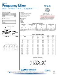
Surface Mount<br />
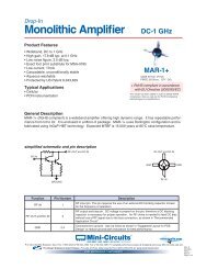
<strong>Monolithic</strong> <strong>Amplifier</strong><br />
Product Features<br />
• DC-4 GHz<br />
• Single Voltage Supply<br />
• Internally Matched to 50 Ohm<br />
• Unconditionally Stable<br />
• Low Performance Variation Over Temperature<br />
• Transient Protected<br />
• Aqueous washable<br />
• Protected By US Patent 6,943,629<br />
Typical Applications<br />
• Cellular/ PCS/ 3G Base Station<br />
• CATV, Cable Modem & DBS<br />
• Fixed Wireless & WLAN<br />
• Microwave Radio & Test Equipment<br />
DC-4 GHz<br />
ERA-6SM+<br />
CASE STYLE: WW107<br />
PRICE: $3.90 ea. QTY. (30)<br />
+ RoHS compliant in accordance<br />
with EU Directive (2002/95/EC)<br />
The +Suffix has been added in order to identify RoHS<br />
Compliance. See our web site for RoHS Compliance<br />
methodologies and qualifications.<br />
General Description<br />
ERA-6SM+ (RoHS compliant) is a wideband amplifier offering high dynamic range. It has repeatable performance<br />
from lot to lot. It is enclosed in a Micro-X package. ERA-6SM+ uses Darlington configuration and<br />
is fabricated using InGaP HBT technology. Expected MTBF is 350 years at 85°C case temperature.<br />
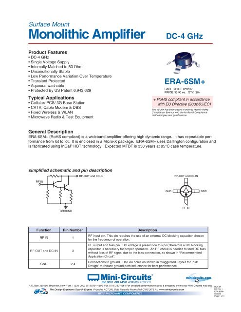
simplified schematic and pin description<br />
RF-OUT and DC-IN<br />
RF-OUT and DC-IN<br />
RF IN<br />
GND<br />
GND<br />
GROUND<br />
RF IN<br />
Function Pin Number Description<br />
RF IN 1<br />
RF-OUT and DC-IN 3<br />
GND 2,4<br />
RF input pin. This pin requires the use of an external DC blocking capacitor chosen<br />
for the frequency of operation.<br />
RF output and bias pin. DC voltage is present on this pin; therefore a DC blocking<br />
capacitor is necessary for proper operation. An RF choke is needed to feed DC bias<br />
without loss of RF signal due to the bias connection, as shown in “Recommended<br />
Application Circuit”.<br />
Connections to ground. Use via holes as shown in “Suggested Layout for PCB<br />
Design” to reduce ground path inductance for best performance.<br />
Mini-Circuits ®<br />
ISO 9001 ISO 14001 AS9100 CERTIFIED<br />
minicircuits.com<br />
P.O. Box 350166, Brooklyn, New York 11235-0003 (718) 934-4500 Fax (718) 332-4661 For detailed performance specs & shopping online see Mini-Circuits web site<br />
REV. M<br />
The Design Engineers Search Engine Provides ACTUAL Data Instantly From MINI-CIRCUITS At: www.minicircuits.com<br />
M117811<br />
ERA-6SM+<br />
RF/IF MICROWAVE COMPONENTS<br />
080516<br />
Page 1 of 4
<strong>Monolithic</strong> InGaP HBT MMIC <strong>Amplifier</strong><br />
ERA-6SM+<br />
Electrical Specifications at 25°C and 70mA, unless noted<br />
Parameter Min. Typ. Max. Units Cpk<br />
Frequency Range* DC 4 GHz<br />
Gain<br />
Magnitude of Gain Variation versus Temperature<br />
(values are negative)<br />
Input Return Loss<br />
Output Return Loss<br />
f=0.1 GHz 12 12.6 13.3 dB ≥ 1.5<br />
f=1 GHz 12.5<br />
f=2 GHz 11.1 11.7 12.3<br />
f=3 GHz 11.7<br />
f=4 GHz 9.8 10.3 10.8<br />
f=0.1 GHz 0.0013 .0025 dB/°C<br />
f=1 GHz 0.0018 .0035<br />
f=2 GHz 0.0021 .004<br />
f=3 GHz 0.0025 .005<br />
f=4 GHz 0.0032 .007<br />
f=0.1 GHz 25 dB<br />
f=1 GHz 30<br />
f=2 GHz 35<br />
f=3 GHz 33<br />
f=4 GHz 28<br />
f=0.1 GHz 35 dB<br />
f=1 GHz 24<br />
f=2 GHz 20<br />
f=3 GHz 20<br />
f=4 GHz 20<br />
Reverse Isolation f=2 GHz 16 19 dB<br />
Output Power @ 1 dB compression<br />
Saturated Output Power<br />
(at 3dB compression)<br />
Output IP3<br />
Noise Figure<br />
f=0.1 GHz 17.1 dBm ≥ 1.33<br />
f=1 GHz 16 17.2<br />
f=2 GHz 17.1<br />
f=3 GHz 16.2<br />
f=4 GHz 14.7<br />
f=0.1 GHz 17.1 dBm<br />
f=1 GHz 17.2<br />
f=2 GHz 17.7<br />
f=3 GHz 17.3<br />
f=4 GHz 15.9<br />
f=0.1 GHz 34 36.5 dBm ≥ 1.33<br />
f=1 GHz 33 35<br />
f=2 GHz 31 33<br />
f=3 GHz 30<br />
f=4 GHz 28.5<br />
f=0.1 GHz 4.4 5.2 dB<br />
f=1 GHz 4.4 5.5<br />
f=2 GHz 4.5 5.5<br />
f=3 GHz 4.5 6<br />
f=4 GHz 4.7 6<br />
Group Delay f=2 GHz 80 psec<br />
Recommended Device Operating Current 70 mA<br />
Device Operating Voltage 4.7 5 5.3 V ≥ 1.5<br />
Device Voltage Variation vs. Temperature at 70mA -3.2 mV/°C<br />
Device Voltage Variation vs. Current at 25°C 11.8 mV/mA<br />
Thermal Resistance, junction-to-case 1 143 °C/W<br />
*Guaranteed specification DC-4 GHz. Low frequency cut off determined by external coupling capacitors.<br />
Absolute Maximum Ratings<br />
Parameter<br />
Ratings<br />
Operating Temperature* -45°C to 85°C<br />
Storage Temperature -65°C to 150°C<br />
Operating Current<br />
85mA<br />
Power Dissipation<br />
451mW<br />
Input Power<br />
20dBm<br />
Note: Permanent damage may occur if any of these limits are exceeded.<br />
These ratings are not intended for continuous normal operation.<br />
1<br />
Case is defined as ground leads.<br />
*Based on typical case temperature rise 5°C above ambient.<br />
Mini-Circuits ®<br />
ISO 9001 ISO 14001 AS9100 CERTIFIED<br />
Page 2 of 4<br />
P.O. Box 350166, Brooklyn, New York 11235-0003 (718) 934-4500 Fax (718) 332-4661 For detailed performance specs & shopping online see Mini-Circuits web site<br />
The Design Engineers Search Engine Provides ACTUAL Data Instantly From MINI-CIRCUITS At: www.minicircuits.com<br />
RF/IF MICROWAVE COMPONENTS<br />
minicircuits.com
<strong>Monolithic</strong> InGaP HBT MMIC <strong>Amplifier</strong><br />
ERA-6SM+<br />
Product Marking<br />
6<br />
Additional Detailed Technical Information<br />
Additional information is available on our web site. To access this information enter the model number on<br />
our web site home page.<br />
Performance data, graphs, s-parameter data set (.zip file)<br />
Case Style: WW107<br />
Plastic micro-x, .085 body diameter, lead finish: tin/silver/nickel<br />
Tape & Reel: F4<br />
Suggested Layout for PCB Design: PL-075<br />
Evaluation Board: TB-408-6+<br />
Environmental Ratings: ENV08T2<br />
Recommended Application Circuit<br />
IN<br />
Cblock<br />
1<br />
Ibias<br />
4<br />
3<br />
2<br />
Rbias (Required)<br />
Vcc<br />
RFC (Optional)<br />
Vd<br />
Cblock<br />
Cbypass<br />
OUT<br />
Test Board includes case, connectors, and components (in bold) soldered to PCB<br />
Vcc<br />
R BIAS<br />
“1%” Res. Values (ohms)<br />
for Optimum Biasing<br />
7 30.1<br />
8 43.2<br />
9 56.2<br />
10 69.8<br />
11 84.5<br />
12 100<br />
13 113<br />
14 127<br />
15 140<br />
16 154<br />
17 169<br />
18 182<br />
19 196<br />
20 210<br />
Mini-Circuits ®<br />
ISO 9001 ISO 14001 AS9100 CERTIFIED<br />
Page 3 of 4<br />
P.O. Box 350166, Brooklyn, New York 11235-0003 (718) 934-4500 Fax (718) 332-4661 For detailed performance specs & shopping online see Mini-Circuits web site<br />
The Design Engineers Search Engine Provides ACTUAL Data Instantly From MINI-CIRCUITS At: www.minicircuits.com<br />
RF/IF MICROWAVE COMPONENTS<br />
minicircuits.com
<strong>Monolithic</strong> InGaP HBT MMIC <strong>Amplifier</strong><br />
ESD Rating<br />
ERA-6SM+<br />
Human Body Model (HBM): Class 1B (500 v to < 1,000 v) in accordance with ANSI/ESD STM 5.1 - 2001<br />
Machine Model (MM): Class M1 ( < 100 v) in accordance with ANSI/ESD STM 5.2 - 1999<br />
MSL Rating<br />
Moisture Sensitivity: MSL1 in accordance with IPC/JEDECJ-STD-020C<br />
No. Test Required Condition Standard Quantity<br />
1 Visual Inspection<br />
Low Power Microscope<br />
Magnification 40x<br />
MIP-IN-0003<br />
(MCT spec)<br />
45 units<br />
2 Electrical Test Room Temperature<br />
SCD<br />
(MCL spec)<br />
45 units<br />
3 SAM Analysis<br />
Less than 10% growth in term of<br />
delamination<br />
J-Std-020C<br />
(Jedec Standard)<br />
45 units<br />
4<br />
Moisture Sensitivity<br />
Level 1<br />
Bake at 125°C for 24 hours<br />
Soak at 85°C/85%RH for 168 hours<br />
Reflow 3 cycles at 260°C peak<br />
J-Std-020C<br />
(Jedec Standard)<br />
45 units<br />
MSL Test Flow Chart<br />
Start<br />
Visual<br />
Inspection<br />
Electrical Test<br />
SAM Analysis<br />
Reflow 3 cycles,<br />
260°C<br />
Soak<br />
85°C/85RH<br />
168 hours<br />
Bake at 125°C,<br />
24 hours<br />
Visual<br />
Inspection<br />
Electrical Test<br />
SAM Analysis<br />
Mini-Circuits ®<br />
ISO 9001 ISO 14001 AS9100 CERTIFIED<br />
Page 4 of 4<br />
P.O. Box 350166, Brooklyn, New York 11235-0003 (718) 934-4500 Fax (718) 332-4661 For detailed performance specs & shopping online see Mini-Circuits web site<br />
The Design Engineers Search Engine Provides ACTUAL Data Instantly From MINI-CIRCUITS At: www.minicircuits.com<br />
RF/IF MICROWAVE COMPONENTS<br />
minicircuits.com