MSR127R-MSR127T - CEDES
MSR127R-MSR127T - CEDES
MSR127R-MSR127T - CEDES

You also want an ePaper? Increase the reach of your titles
YUMPU automatically turns print PDFs into web optimized ePapers that Google loves.
R<br />
MINOTAUR<br />
<strong>MSR127R</strong>-<strong>MSR127T</strong><br />
(a)<br />
MONITORING SAFETY RELAY<br />
ÜBERWACHUNGS-/SICHERHEITSRELAIS<br />
RELAIS DE SECURITE POUR CONTROLE<br />
(b) Installation Instructions<br />
RETAIN THESE INSTRUCTIONS<br />
Installation must be in accordance with the following steps and must be carried out<br />
by suitably competent personnel.<br />
This device is intended to be part of the safety related control system of a<br />
machine. Before installation, a risk assessment should be performed to determine<br />
whether the specifications of this device are suitable for all foreseeable<br />
operational and environmental characteristics of the machine to which it is to be<br />
fitted.<br />
At regular intervals during the life of the machine check whether the<br />
characteristics foreseen remain valid.<br />
Guardmaster cannot accept responsibility for a failure of this device if the<br />
procedures given in this sheet are not implemented or if it is used outside the<br />
recommended specifications in this sheet.<br />
Exposure to shock and/or vibration in excess of those stated in IEC 68 part: 2-6/7<br />
should be prevented.<br />
Adherence to the recommended inspection and maintenance instructions forms<br />
part of the warranty.<br />
Einbauanleitung<br />
DIESE ANLEITUNG AUFBEWAHREN<br />
Die Installation muß unter Einhaltung der nachstehend beschriebenen<br />
Schritte, und durch geeignetes, fachlich qualifiziertes Personal erfolgen.<br />
Diese Vorrichtung ist als Teil des sicherheitsrelevanten Kontrollsystems<br />
einer Maschine vorgesehen. Vor der Installation sollte eine<br />
Risikobewertung zur Festlegung dessen erfolgen, ob die Spezifikationen<br />
dieser Vorrichtung für alle vorhersehbaren betrieblichen und<br />
umweltbezogenen Eigenschaften der jeweiligen Maschine geeignet sind,<br />
an der sie installiert werden soll.<br />
In regelmäßigen Abständen während der Lebensdauer der Maschine ist zu<br />
überprüfen, ob die vorhergesehenen Eigenschaften weiterhin gültig sind.<br />
Guardmaster kann keinerlei Verantwortung für ein Versagen dieser<br />
Vorrichtung übernehmen, wenn die in diesem Schriftblatt gegebenen<br />
Verfahrensweisen nicht implementiert wurden, oder wenn sie außerhalb<br />
der auf diesem Schriftblatt empfohlenen Spezifikationen verwendet wird.<br />
Eine Aussetzung an Stoßbelastungen und/oder Vibrationen, die überhalb<br />
den in IEC 68, Teil 2-6/7 angegebenen Werten liegen, sollte verhindert<br />
werden.<br />
Die Einhaltung der empfohlenen Inspektions- und Wartungsvorschriften ist<br />
Teil der Garantie.<br />
Notice D'installation<br />
CONSERVEZ CES INSTRUCTIONS<br />
L’installation doit être effectuée conformément aux instructions suivantes,<br />
par des membres qualifiés du personnel.<br />
Ce dispositif est étudié pour être incorporé dans le système de contrôle<br />
pour la sécurité d’une machine. Avant l’installation, on doit effectuer une<br />
évaluation des risques pour déterminer si les spécifications de ce dispositif<br />
sont appropriées pour toutes les caractéristiques de service et du milieu<br />
d’utilisation prévues pour la machine sur laquelle il sera monté.<br />
Vérifier, à des échéances régulières au cours de la vie de la machine, que<br />
les caractéristiques prévues sont toujours valables. Guardmaster décline<br />
toute responsabilité pour les défaillances de cet appareil si les procédures<br />
décrites dans la présente notice ne sont pas appliquées ou si l’appareil est<br />
utilisé hors des spécifications recommandées dans cette même notice.<br />
Eviter toute exposition à des chocs et/ou des vibrations supérieurs à ceux<br />
qui sont spécifiés dans la norme IEC 68 part. 1-6/7.<br />
Le respect des instructions relatives à l'inspection, au contrôle et à<br />
l'entretien de cet appareil rentre dans l'application de la garantie.<br />
(c) Mode of Operation<br />
The dual-channel operation shown in wiring examples 5 and 6 includes crossfault<br />
monitoring between both E-stop circuits. That means in case of shorts between the<br />
two E-stop channels the MSR127 will de-energise the outputs. This is achieved by<br />
an electronic protection circuit in the safety relay. After elimination of the<br />
malfunction, the MSR127 is ready for operation again.<br />
MSR 127R VERSION<br />
The versions with monitored start supervise the start circuit and will only activate<br />
the MSR127 if contacts via terminals S12 and S34 are closing during start<br />
conditions.<br />
<strong>MSR127T</strong><br />
Models with autostart function will be activated automatically by the supply<br />
voltage, if the E-stop circuits and the feedback loop are closed.<br />
A start-push-button may be integrated between the feedback-loop (S12-S34) for<br />
manual reset.<br />
In autostart-applications where both circuits are not closed simultaneously, (e.g.<br />
safety gates) channel 2 has to be activated before channel 1.<br />
If the inputs of the MSR127 are activated with external 24VDC, the negative pole<br />
has to be connected to S21 (e.g. Light curtain applications). In those applications<br />
power supply on A1-A2 is only necessary to drive the Power-LED.<br />
To control NC contacts from external contactors the feed-back loop should be<br />
connected in series between S12 and S34.<br />
The relay is available with fixed or removable terminals.<br />
1<br />
Deutsch / Français<br />
(a) Rückansicht / Vue de l'arrière<br />
(b) Spannung abschalten/ Isoler les<br />
alimentations<br />
(c) Auf 35mm-Normschiene anbringen /<br />
Montage sur rail DIN 35mm<br />
(d) In Einbaugehäuse nach mind. IP 54<br />
montieren / Monter dans un coffret<br />
conforme au minimum à la norme IP 54<br />
2<br />
(b)<br />
A1 & A2 = Spannungsversorgung<br />
S52 & S12 = Schutzeingang (Ruhekontakt)<br />
S21 & S22 = Schutzeingang (Ruhekontakt)<br />
S11 & S52 = Schutzeingang (einkanalig)<br />
(Ruhekontakt)<br />
S12 & S34 = Überwachungsrückmeldungschleife<br />
einschlie lich Rückstellung-Taster<br />
13 & 14 = Schutzausgang 1 (Arbeitskontakt)<br />
23 & 24 = Schutzausgang 2 (Arbeitskontakt)<br />
33 & 34 = Schutzausgang 3 (Arbeitskontakt)<br />
41 & 42 = Hilfsausgang (Ruhekontakt) /<br />
A1 & A2 = Alimentation<br />
S52 & S12 = Entrée de sécurité (N/F)<br />
S21 & S22 = Entrée de sécurité (N/F)<br />
S11 & S52 = Entrée de sécurité (monocanal)<br />
(N/F)<br />
S12 & S34 = Boucle de retour de contrôle<br />
avec bouton d'initialisation incorporé<br />
13 & 14 = Sortie de sécurité 1 (N/O)<br />
23 & 24 = Sortie de sécurité 2 (N/O)<br />
33 & 34 = Sortie de sécurité 3 (N/O)<br />
41 & 42 = Sortie auxiliaire (N/F)<br />
41 & 42 = sortie auxiliaire 1 (N/F)<br />
1<br />
Funktionsweise<br />
Bei 2-kanaliger Ansteuerung gemäß Schaltungsbeispielen 5 und 6 besteht<br />
Querschlußsicherheit. Das heißt, bei einem Leitungsschluss spricht eine<br />
elektronische Sicherung im Gerät an und schaltet das <strong>MSR127R</strong>TP aus.<br />
Nach Beseitigung des Fehlers ist das <strong>MSR127R</strong>TP wieder betriebsbereit.<br />
Bei Geräten mit überwachtem Start wird der Starttaster bei jedem Einschaltvorgang<br />
überprüft. Ist der Eintaster vor dem Entriegeln der Not-Aus-Taster<br />
oder Anlegen der Ver-sorgungsspannung geschlossen, ist kein Start möglich.<br />
Geräte mit Autostartfunktion schalten automatisch bei anliegender Versorgungsspannung<br />
ein, sofern die Not-Aus Kreise und der Rückführkreis geschlossen<br />
sind. Ein Starttaster kann auch hier in den Rückführkreis (S12-S34) eingebunden<br />
werden (manueller Start).<br />
Werden bei Autostart-Anwendungen die Not-Aus Kreise nicht gleichzeitig betätigt,<br />
so muß Kanal 2 vor Kanal 1 geschlossen werden (z. B. Schutztürüberwachung).<br />
Werden die Eingänge des <strong>MSR127R</strong>TP, beispielsweise durch ein<br />
Sicherheitslichtgitter, extern mit 24VDC angesteuert, so ist das negative Potential<br />
mit S21 zu verbinden.<br />
Zu überwachende Öffnerkontakte von externen Erweiterungen sind zwischen S12<br />
und S34 bzw. in Reihe mit dem Starttaster zu schalten.<br />
Die Geräte sind wahlweise mit festen oder abnehmbaren Klemmenblöcken<br />
erhältlich.<br />
(a) Back View<br />
(b) Isolate power<br />
(c) Mount on 35mm DIN rail.<br />
(d) Mount in enclosure to a min. of IP 54.<br />
(c) LED Anzeigen:<br />
Strom (GRÜN) - Leuchtet auf, wenn<br />
Strom eingeschaltet ist<br />
CH1 (GRÜN) - Leuchtet auf, wenn K1<br />
geschlossen ist<br />
CH2 (GRÜN) - Leuchtet auf, wenn K2<br />
geschlossen ist /<br />
Voyants:<br />
Alimentation (VERTE) - allumée à la mise<br />
sous tension<br />
CH1 (VERTE) - allumée lorsque K1 est<br />
fermé<br />
CH2 (VERTE) - allumée lorsque K2 est<br />
fermé<br />
2 (a) Connections / Anschlüsse / Connexions<br />
(b)<br />
A1 & A2 = Power<br />
S52 & S12 = Safety input (N/C)<br />
S21 & S22 = Safety input (N/C)<br />
S11 & S52 = Safety input (single channel) (N/C)<br />
S12 & S34 = Monitoring feedback loop<br />
Incorporating reset button<br />
13 & 14 = Safety output 1 (N/O)<br />
23 & 24 = Safety output 2 (N/O)<br />
33 & 34 = Safety output 3 (N/O)<br />
41 & 42 = Auxilary output (N/C)<br />
Mode de Fonctionnement<br />
La configuration bi-canal illustrée dans les exemples de câblage 3 et 5 prévoit le<br />
contrôle des défaillances entre les deux circuits d'arrêt d'urgence. En cas de courtcircuit<br />
entre les deux canaux d'arrêt d'urgence, le <strong>MSR127R</strong>TP désactive donc les<br />
sorties grâce au circuit de protection électronique prévu dans le relais de sécurité.<br />
Après élimination du défaut, le <strong>MSR127R</strong>TP est de nouveau prêt à fonctionner.<br />
Les versions à initialisation contrôlée commandent le circuit de mise en route et<br />
activent uniquement le <strong>MSR127R</strong>TP si les contacts des bornes S12 et S14 se<br />
ferment pendant l'initialisation.<br />
Les modèles à fonction d'autoinitialisation sont automatiquement activés par la<br />
tension d'alimentation si les circuits d'arrêt d'urgence et la boucle de retour sont<br />
fermés.<br />
Il est possible de monter un bouton de lancement entre la boucle de feed-back<br />
(S12-S34) pour prévoir l'initialisation manuelle.<br />
Pour les applications à initialisation automatique dans lesquelles les deux circuits<br />
se ferment simultanément (par exemple les portes de sécurité), le canal 2 doit<br />
être activé avant le canal 1.<br />
Si les entrées du <strong>MSR127R</strong>TP sont activées par une alimentation externe de 24 V<br />
c.c., le pôle négatif doit être connecté à S21 (par ex. pour les barrières<br />
photoélectriques). Dans ces applications, l'alimentation électrique de A1-A2 est<br />
uniquement sollicitée pour alimenter le voyant de marche.<br />
Pour commander les contacts N/F à partir des contacteurs externes, connecter la<br />
boucle de retour en série entre S12 et S34.<br />
Le relais est disponible avec bornes fixes ou amovibles.<br />
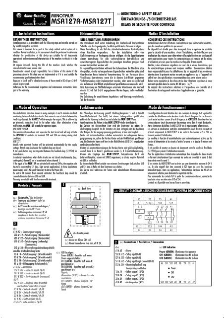
(d) CIRCUIT DIAGRAM/AUSCHLUSSDIAGRAMM/SCHEMA DES CONNEXIONS<br />
13 23 33 41<br />
A1 S11(+) S52 S12<br />
S12<br />
13 23 33 41<br />
K1<br />
S21<br />
S52<br />
K2<br />
S22 14 24 34 42<br />
S21(-) S22 S34 A2<br />
14 24 34 42<br />
(c) LED Indication<br />
Power (GREEN) - Illuminates when power on<br />
CH1 (GREEN) - Illuminates when K1 is closed<br />
CH2 (GREEN) - Illuminates when K2 is closed<br />
A1 S11 S52 S12 13 23 33 41<br />
Power<br />
CH1<br />
CH2<br />
S21 S22 S34 A2 14 24 34 42
Deutsch / Français<br />
3<br />
(b) Lichtschranke<br />
Ausgang 1 Ausgang 2 /<br />
Barrière photoélectrique<br />
Out 1 Out 2<br />
(c) Rückstellung / Initialisation<br />
(d) Lichtschranke, manuelle Rückstellung,<br />
überwachter Ausgang /<br />
Barrière photoélectrique, initialisation<br />
manuelle, sortie non contrôlée<br />
3 (a) Wiring example 1 / Anschlußbeispiele 1 / Exemples de câblage 1<br />
L1<br />
N<br />
A1<br />
Light Curtain, 24VDC<br />
Out 1 Out 2<br />
S11<br />
S52<br />
<strong>MSR127R</strong>P<br />
(d)<br />
S12<br />
S21 S22 S34 A2<br />
(b)<br />
Reset<br />
13 23 33 41<br />
14 24<br />
K1<br />
K2<br />
34 42<br />
(c)<br />
K1<br />
K2<br />
Light Curtain, Manual Reset,<br />
Monitored Output<br />
L1 L2 L3<br />
M<br />
4<br />
(b) Einkanal-Notaus, automatische<br />
Rückstellung, keine<br />
Ausgangsüberwachung / A.d'urgence<br />
monocanal, autoinitialisation, sortie non<br />
contrôlée<br />
4 (a) Wiring example 2 / Anschlußbeispiele 2 / Exemples de câblage 2<br />
L1<br />
E-Stop<br />
L1 L2 L3<br />
A1<br />
S11<br />
S52<br />
S12<br />
13 23 33 41<br />
<strong>MSR127T</strong>P<br />
K1<br />
S21 S22 S34 A2<br />
14 24<br />
34 42<br />
N<br />
K1<br />
M<br />
(b)<br />
Single Channel E-Stop, Auto. Reset,<br />
No Output Monitoring<br />
5<br />
(b) Rückstellung / Initialisation<br />
(c) Zweikanal-Notaus, manuelle<br />
Rückstellung, überwachter Ausgang/<br />
A.d'urgence bi-canal, initialisation<br />
manuelle, sortie contrôlée<br />
5 (a) Wiring example 3 / Anschlußbeispiele 3 / Exemples de câblage 3<br />
L1<br />
E-Stop<br />
A1 S11 S52<br />
S12<br />
(b)<br />
Reset<br />
13 23 33 41<br />
L1 L2 L3<br />
<strong>MSR127R</strong>P<br />
K1<br />
N<br />
S21 S22 S34 A2<br />
(c)<br />
14 24<br />
K1<br />
K2<br />
34 42<br />
K2<br />
Dual Channel E-Stop, Manual Reset,<br />
Monitored Output<br />
M<br />
6<br />
(b) Zweikanal-Sicherheitstore, automatische<br />
Rückstellung, überwachter Ausgang /<br />
Portes de sécurité bi-canal,<br />
autoinitialisation, sortie contrôlée<br />
6 (a) Wiring example 4 / Anschlußbeispiele 4 / Exemples de câblage 4<br />
L1<br />
L1 L2 L3<br />
open<br />
A1<br />
S11<br />
S52<br />
S12<br />
13 23 33 41<br />
<strong>MSR127T</strong>P<br />
K1<br />
K2<br />
closed<br />
S21 S22 S34 A2<br />
14 24<br />
34 42<br />
N<br />
(b)<br />
K1<br />
K2<br />
Dual Channel Safety Gates, Auto.<br />
Reset, Monitored Output<br />
M
7<br />
(a) Abnehmbare Klemmen - nur bei ‘P’-<br />
Ausführungen / Bornes amovibles –<br />
disponibles sur versions P uniquement<br />
(b) Um die Klemmen abzunehmen -<br />
Schraubenzieher in Position 1 ansetzen<br />
und langsam in Position 2 bringen/<br />
Pour ôter les bornes : insérer un tournevis<br />
au repère 1 et baisser lentement jusqu'au<br />
repère 2<br />
(c) Position 1 / Repère 1<br />
(d) Position 2 / Repère 2<br />
7<br />
(a) Removable Terminals<br />
available on 'P' versions only<br />
(c) Position 1<br />
(b) To remove terminals - Insert screwdriver as<br />
Position 1 and move slowly to Position 2<br />
(d) Position 2<br />
(e) DIMENSION DIAGRAM/ABMESSUNGSDIAGRAMM/SCHEMA COTÉ<br />
Dimensions - mm (in)<br />
99 (3.89)<br />
22.5 (0.88)<br />
114.5<br />
(4.5)<br />
(f) Technical Specifications<br />
Standards<br />
IEC/EN60204-1, ISOTR12100,<br />
ISO13849-1(EN954-1)<br />
Safety Category Cat. 4 per EN 954-1<br />
Approvals<br />
CE marked for all applicable<br />
directives, cULus and BG<br />
Power Supply<br />
24V AC/DC, 115V AC or 230V AC<br />
0.85 to 1.1 x rated voltage, 50/60 Hz<br />
Power Consumption<br />
2W<br />
Safety Inputs<br />
1 N.C. or 2 N.C. or 2 PNP light curtain<br />
Input Simultaneity<br />
Infinite<br />
Max. Allowable Input Resistance 110 ohms<br />
Reset<br />
Monitored Manual or Auto./Manual<br />
Outputs<br />
3 N.O. Safety; 1N.C. Auxiliary<br />
Output Rating<br />
B300, AC-15, 5A/250V AC<br />
B300/P300 ref.: Ith, Ui P300, DC-13, 3A/24V DC<br />
Fuses Output (external) 6A Slow Blow or 10A Quick Blow<br />
Min. Switched Current/Voltage 10mA/10V<br />
Contact Material<br />
AgSnO 2 + 0.5µAu<br />
Power On Delay<br />
1s<br />
Response Time<br />
15ms<br />
Recovery Time<br />
100ms<br />
Impulse Withstand Voltage 2500V<br />
Pollution Degree 2<br />
Operating Temperature -5°C to +55°C (+23°F to 131°F)<br />
Humidity<br />
90% RH<br />
Enclosure Protection IP40 (NEMA 1)<br />
Terminal Protection<br />
IP20<br />
Conductor Size<br />
0.2-4mm 2 (24-12AWG)<br />
Torque Settings - terminal screws 0.4 Nm (3.54 lb•in)<br />
Case Material Polyamide PA 6.6<br />
Mounting<br />
35mm DIN rail<br />
Weight 24V DC 210g (0.463lbs)<br />
115V AC or 230V AC 260g (0.573lbs)<br />
Electrical Life<br />
222V AC/4A/880VA cos=0.35 100,000 operations<br />
220V AC/1.7A/375VA cos=0.6 500,000 operations<br />
30V DC/2A/60W 1,000,000 operations<br />
10V DC/0.01A/0.1W 2,000,000 operations<br />
Mechanical Life<br />
2,000,000 cycles<br />
Vibration<br />
10-55 Hz, 0.35mm<br />
Shock<br />
10g, 16ms, 100 shocks<br />
Technische Daten<br />
Normen<br />
IEC/EN60204-1, ISOTR12100,<br />
ISO13849-1(EN954-1)<br />
Schutzkategorie Kat. 4 gem. EN 954-1<br />
Zulassungen<br />
CE-Kennzeichnung für alle<br />
zutreffenden Direktiven, cULus und BG<br />
Stromversorgung<br />
24V AC/DC, 115V AC ode 230V AC<br />
0,85 bis 1,1 x Nennspannung, 50/60 Hz<br />
Leistungsverbrauch<br />
2W<br />
Schutzeingänge<br />
1 Ruhekontakt oder 2 Ruhekontakt<br />
oder 2 PNP Lichtschranken<br />
Eingangsgleichzeitigkeit Unbegrenzt<br />
Max. zulässiger Eingangswiderstand 110 ohms<br />
Rückstellung<br />
überwachte manuelle oder<br />
automatische/manuelle<br />
Ausgänge<br />
3 Arbeitskontakt-Schutzausgang;<br />
1 Ruhekontakt-Hilfsausgang<br />
Ausgangsnennbelastung B300, AC-15, 5A/250V AC<br />
B300/P300 ref.: Ith, Ui P300, DC-13, 3A/24V DC<br />
Sicherungen Ausgang (extern) 6A träge oder 10A flinke<br />
Min. geschalteter Strom/Spannung 10mA/10V<br />
Kontaktmaterial<br />
AgSnO 2 + 0.5µAu<br />
Strom-ein-Verzögerung 1s<br />
Reaktionszeit<br />
15ms<br />
Erholungszeit<br />
100ms<br />
Stehstossspannung<br />
2500V<br />
Verschmutzungsgrad 2<br />
Betriebstemperatur<br />
-5°C bis +55°C (+23°F to 131°F)<br />
Feuchtigkeit<br />
90% RH<br />
Gehäuseschutz IP40 (NEMA 1)<br />
Klemmenschutz<br />
IP20<br />
Leiterquerschnitt<br />
0.2-4mm 2 (24-12AWG)<br />
Drehmomentwerte - Klemmenschrauben 0.4 Nm (3.54 lb•in)<br />
Gehäusematerial Polyamid PA 6.6<br />
Befestigung<br />
Gewicht<br />
35mm DIN-Schiene<br />
24V DC 210g (0.463lbs)<br />
115V AC oder 230V AC 260g (0.573lbs)<br />
Elektrische Lebensdauer<br />
222V AC/4A/880VA cos=0.35 100,000 Betätigungen<br />
220V AC/1.7A/375VA cos=0.6 500,000 Betätigungen<br />
30V DC/2A/60W 1,000,000 Betätigungen<br />
10V DC/0.01A/0.1W 2,000,000 Betätigungen<br />
Mechanische Lebensdauer 2,000,000 Arbeitstakte<br />
Vibration<br />
10-55 Hz, 0.35mm<br />
Stösse<br />
10g, 16ms, 100 Stösse<br />
Spécifications Techniques<br />
Normes<br />
IEC/EN60204-1, ISOTR12100,<br />
ISO13849-1(EN954-1)<br />
Classe de sécurité Cat. 4 selon EN 954-1<br />
Homologations<br />
label CE pour toutes les directives<br />
applicables, cULus et BG<br />
Alimentation électrique 24V c.a./c.c., 115V c.a. ou 230V c.a.<br />
0,85 à 1,1 x tension nominale, 50/60 Hz<br />
Consommation<br />
2W<br />
Contacts d'entrée de sécurité 1 ou 2 N/F ou 2 PNP barrière<br />
photoélectrique<br />
Simultanéité des entrées infinie<br />
Résistance maximale d'entrée 110 ohms<br />
Initialisation<br />
manuelle contrôlée ou<br />
manuelle/automatique<br />
Contacts de sortie<br />
3 N/O de sécurité, 1 N/F auxiliaire<br />
Puissance nominale de sortie B300, c.a.-15, 5 A / 250 V c.a.<br />
B300/P300 ref.: Ith, Ui P300, c.c.-13, 3 A / 24 V c.c.<br />
Fusibles Sortie (externe) 6A à fusion retardée ou 10A à fusion<br />
rapide<br />
Intensité/tension commutée min. 10mA/10V<br />
Matière de contact<br />
AgSnO 2 + 0.5µAu<br />
Délai de mise sous tension 1s<br />
Temps de réponse<br />
15ms<br />
Temps de rétablissement 100ms<br />
Tension impulsionnelle admise 2500V<br />
Indice de pollution 2<br />
Température de service -5°C to +55°C<br />
Humidité<br />
90% HR<br />
Indice de protection enceinte IP40 (NEMA 1)<br />
Protection aux bornes<br />
IP20<br />
Diamètre conducteur<br />
0.2-4mm 2 (24-12AWG)<br />
Couple des vis de bornes 0.4 Nm<br />
Composition du boîtier polyamide PA 6.6<br />
Montage<br />
rail DIN de 35 mm<br />
Poids 24V c.c. 210g<br />
115V c.a. ou 230V c.a. 260g<br />
Durée de vie électrique<br />
222V c.a./4A/880VA cos=0.35 100,000 d'opérations<br />
220V c.a./1.7A/375VA cos=0.6 500,000 d'opérations<br />
30V c.c./2A/60W 1,000,000 d'opérations<br />
10V c.c./0.01A/0.1W 2,000,000 d'opérations<br />
Durée de vie mécanique 2,000,000 de cycles<br />
Vibrations<br />
10-55 Hz, 0.35mm<br />
Chocs<br />
10g, 16ms, 100 chocs
(g) REPAIR<br />
If there is any malfunction or damage, no attempts should be made to repair<br />
it. The unit should be replaced before machine operation is allowed.<br />
DO NOT DISMANTLE THE UNIT.<br />
REPARATUR<br />
Falls Fehlfunktionen oder Schäden auftreten, keine Versuche zur Reparatur<br />
unternehmen. Der Schalter muß ersetzt werden, bevor die Maschine wieder<br />
gestartet wird.<br />
GERÄT DARF NIEMALS GEÖFFNET WERDEN!<br />
REPARATION<br />
Dans l'éventualité d'un problème technique ou d'une détérioration de cet<br />
appareil, il doit être remplacé immédiatement avant la remise en production<br />
de la machine.<br />
DANS TOUS LES CAS, NE DISLOQUEZ PAS L'APPAREIL.<br />
Declaration of Conformity / Konformitätserklärung / Déclaration de conformité<br />
This is to declare that the Guardmaster <strong>MSR127R</strong>/T conforms with the Essential Health & Safety Requirements (EHSR's) of the European Machinery Directive<br />
(98/37/EC), the relevant requirements of the Low Voltage Directive (73/23/EEC as amended by 93/68 EEC) and the essential protection requirements of the EMC<br />
Directive (89/336/EEC as amended by 92/31 EEC). The <strong>MSR127R</strong>/T also conforms to EN 292, EN 60204-1, EN 954-1, UL 508.<br />
Signed for Guardmaster Ltd<br />
S. F. Mitchell<br />
Managing Director<br />
R<br />
Drg No: 57516 / Issue No: 2<br />
Change No: 16624