Thermistors Introduction
Thermistors Introduction
Thermistors Introduction

You also want an ePaper? Increase the reach of your titles
YUMPU automatically turns print PDFs into web optimized ePapers that Google loves.
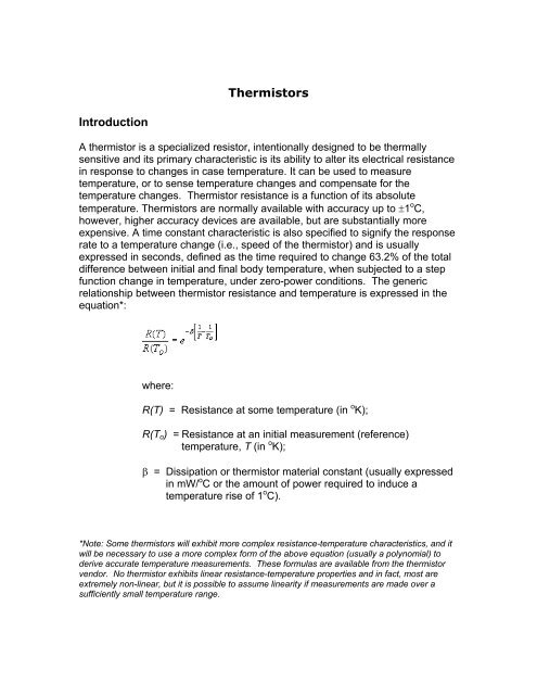
<strong>Thermistors</strong><br />
<strong>Introduction</strong><br />
A thermistor is a specialized resistor, intentionally designed to be thermally<br />
sensitive and its primary characteristic is its ability to alter its electrical resistance<br />
in response to changes in case temperature. It can be used to measure<br />
temperature, or to sense temperature changes and compensate for the<br />
temperature changes. Thermistor resistance is a function of its absolute<br />
temperature. <strong>Thermistors</strong> are normally available with accuracy up to ±1 o C,<br />
however, higher accuracy devices are available, but are substantially more<br />
expensive. A time constant characteristic is also specified to signify the response<br />
rate to a temperature change (i.e., speed of the thermistor) and is usually<br />
expressed in seconds, defined as the time required to change 63.2% of the total<br />
difference between initial and final body temperature, when subjected to a step<br />
function change in temperature, under zero-power conditions. The generic<br />
relationship between thermistor resistance and temperature is expressed in the<br />
equation*:<br />
where:<br />
R(T) = Resistance at some temperature (in o K);<br />
R(T o ) = Resistance at an initial measurement (reference)<br />
temperature, T (in o K);<br />
β = Dissipation or thermistor material constant (usually expressed<br />
in mW/ o C or the amount of power required to induce a<br />
temperature rise of 1 o C).<br />
*Note: Some thermistors will exhibit more complex resistance-temperature characteristics, and it<br />
will be necessary to use a more complex form of the above equation (usually a polynomial) to<br />
derive accurate temperature measurements. These formulas are available from the thermistor<br />
vendor. No thermistor exhibits linear resistance-temperature properties and in fact, most are<br />
extremely non-linear, but it is possible to assume linearity if measurements are made over a<br />
sufficiently small temperature range.
Packaging<br />
<strong>Thermistors</strong> are available in several package types. The most common package<br />
is a disk, although they are also available with axial leads and can be purchased<br />
as chip or Metal Electrode Leadless Faces (MELF) components for surface<br />
mount applications. Selection of packaging style depends on the application and<br />
where the temperature measurement needs to be made. Surface mounted chip<br />
thermistors will only be able to measure the temperature very close to the board,<br />
while disk styles can be mounted at a substantial distance above the board if the<br />
airflow needs to be sampled. <strong>Thermistors</strong> are also available as temperature<br />
probes for specialized applications.<br />
Failure Mechanisms and Anomalies<br />
The most common failure mode of a thermistor<br />
is an open circuit, as shown in<br />
Table 1. The cause of such failures are usually<br />
due to mechanical separation between the<br />
resistor element and the lead material, caused<br />
by handling damage, excessive heat, thermal<br />
mismatch, etc. The second most common<br />
failure mode is drift in resistance value as the<br />
thermistor ages, or parameter change. This<br />
results in inaccurate temperature<br />
Table 1. Normalized Failure Mode<br />
Distributions for <strong>Thermistors</strong> 1[1]<br />
Failure Mode Relative Probability<br />
Open 63%<br />
Parameter Change 22%<br />
Short 15%<br />
measurements, thereby causing the thermistor circuit to provide incorrect thermal<br />
compensation as it ages. A short circuit is the least common failure mode, but it<br />
is important to note that a thermistor is much more likely to fail in the short circuit<br />
mode than a normal, fixed value resistor (by about a factor of 3).<br />
The unfortunate consequence of thermistor failures is they often cause<br />
substantial secondary damage to other circuit elements when they fail. This<br />
occurs because thermistors are often used as protection devices against<br />
excessive heat. In addition, failure of a thermistor often goes undiagnosed due<br />
to this secondary damage, particularly if the thermistor fails in the parameter drift<br />
mode. For example, one common thermistor application is to provide protection<br />
against excessive heat in a power supply. If the thermistor performs incorrectly,<br />
the power supply may run warmer than expected and eventually fail. Failure is<br />
then blamed on whatever part failed in the power supply rather than the<br />
thermistor. The reverse can also occur, where a protection circuit incorrectly<br />
provides protection when it is not needed. This results in premature shutdown.
Figure1. Relative Failure Rates for <strong>Thermistors</strong><br />
Reliability<br />
The reliability of<br />
thermistors is<br />
comparable to<br />
wirewound<br />
resistor styles,<br />
but failure rates<br />
vary substantially<br />
with style. Figure<br />
1 shows the<br />
relative difference<br />
between failure<br />
rates of the three<br />
principle forms.<br />
As shown, beadforms<br />
are<br />
generally the<br />
most reliable and<br />
rod-forms the least.<br />
Figure 2. Derating Requirements for <strong>Thermistors</strong><br />
For thermistors with negative temperature coefficients, care must be taken to<br />
avoid thermal runaway due to self-heating effects because it can produce<br />
permanent changes to thermistor properties. Current limiting resistors can help<br />
prevent thermal runaway conditions.<br />
Derating<br />
Derate power to 50% of maximum full rated power below T S . Above T S , linearly<br />
derate to T D , as shown in Figure 2, where<br />
. The temperatures
given in Figure 2 are for thermistors conforming to the requirements of MIL-T-<br />
23648 (Style RTH).<br />
Design & Material<br />
A thermistor is a mixture of metal oxides fused at high temperature to a sintered<br />
ceramic-like semiconductor material. As previously discussed in Technologies<br />
section, thermistors are available in four principle forms: disk, bead, rod, and<br />
chip. The chip styles are the only ones available with silver or gold plated<br />
terminations.<br />
Facility Assessment & Quality<br />
The quality control provisions for military thermistor types are covered through<br />
MIL-T-23648, “Thermistor (Thermally Sensitive Resistor) Insulated, General<br />
Specification for.” <strong>Thermistors</strong> conforming to MIL-T-23648 are required to<br />
undergo the qualification inspections/tests given in Table 2.<br />
Sampling<br />
Every thermistor vendor imposes some type of sampling plan to control the<br />
quality and uniformity of the product, but the type of sampling will vary between<br />
vendors. <strong>Thermistors</strong> conforming to MIL-T-23648 require sampling at specific lot<br />
sizes and are considered nonconforming if the number of defects exceeds a<br />
given value. Consult MIL-T-23648 to find specific sample lot sizes and the<br />
number of allowable defects, as they are dependent on type of test given in<br />
Table 2.<br />
Table 2. List of Required Qualification Tests for <strong>Thermistors</strong> Conforming to MIL-T-23648<br />
Visual and Mechanical Inspection<br />
Zero-Power Resistance<br />
Resistance Ratio<br />
Solderability<br />
Resistance to Solvents<br />
Short Time Overload<br />
Insulation Resistance<br />
Dielectric Withstanding Voltage<br />
Low Temperature Storage<br />
High Temperature Storage<br />
Immersion<br />
Dissipating Constant<br />
Thermal Time Constant<br />
Terminal Strength<br />
Resistance to Temperature Characteristics<br />
Thermal Shock<br />
Resistance to Soldering Heat<br />
Moisture Resistance<br />
Load Life<br />
High Temperature Exposure<br />
Vibration, High Frequency<br />
Shock
Process Controls<br />
The process controls of Military grade thermistors are controlled though the<br />
requirements of MIL-T-23648. Process controls for industrial and commercial<br />
grade thermistors will vary.<br />
Part Assessment<br />
Additional qualification testing or screening by the user is not typically performed.<br />
Additional qualification testing or screening by the user should be left up to the<br />
discretion of the user and is dependent on the specific application. Qualification<br />
testing by the user is not typically performed, although testing can be done to<br />
determine the initial measurement reference temperature (R(T o )).<br />
Handling & Storage Precautions<br />
Thermistor construction is very rugged, especially for the bead-forms.<br />
<strong>Thermistors</strong> are not considered to be ESD sensitive.<br />
Closing Comments<br />
Surface mounted chip thermistors are intended to measure temperature very<br />
close to the board. If temperature needs to be measured at a substantial<br />
distance above the board or if the airflow needs to be sampled, disk packages<br />
are a better choice. The designer has the choice of three different types of<br />
devices available to measure temperature: the resistance temperature detector<br />
(RTD), thermocouple, and the thermistor. This section is only applicable to the<br />
thermistor, however, to aid the designer in choosing the best device for a given<br />
application, the following descriptions and characteristic curves (Figure 3) are<br />
offered:<br />
a. The RTD is constructed similar to an accurate wire wound resistor. It is<br />
most accurate of the three types of temperature sensing devices because it has<br />
the best stability and the best linear response. Its main disadvantages are a slow<br />
response time, small resistance change, and it is sensitive to self-heating effects.
Figure 3. Comparison of Output Characteristics of Three Temperature Sensor<br />
Technologies<br />
b. The thermocouple is constructed with two dis-similar metals joined<br />
together and takes advantage of the thermoelectric potential property of<br />
dissimilar metal junctions. The main advantages of a thermocouple are that a<br />
current source is not necessary and it has the largest temperature range of the<br />
three types of temperature sensors. The primary disadvantages are a low<br />
voltage (mV) output, a reference (cold junction) temperature is needed, and it<br />
has the lowest sensitivity of the three types.<br />
c. The thermistor has much higher resistance values and exhibits a larger<br />
change in resistance with respect to temperature, but its temperature range is<br />
very limited in comparison to the other two types of temperature sensors.<br />
[1]Failure Mode data for Table 1 was taken from a combination of MIL-HDBK-<br />
978, “NASA Parts Application Handbook,” 1991; MIL-HDBK-338, “Electronic<br />
Reliability Design Handbook,” 1994; Reliability Toolkit: Commercial Practices<br />
Edition,” Reliability Analysis Center (RAC), 1998; and “Failure Mode, Effects and<br />
Criticality Analysis (FMECA),” RAC, 1993.