The New Object-Oriented Modeling Language - Modelica
The New Object-Oriented Modeling Language - Modelica
The New Object-Oriented Modeling Language - Modelica

You also want an ePaper? Increase the reach of your titles
YUMPU automatically turns print PDFs into web optimized ePapers that Google loves.
<strong>The</strong> 12th European Simulation Multiconference, ESM'98, June 16--19, 1998, Manchester, UK<br />
MODELICA — THE NEW OBJECT-ORIENTED MODELING LANGUAGE<br />
Hilding Elmqvist<br />
Dynasim AB<br />
Research Park Ideon<br />
SE-223 70 Lund, Sweden<br />
E-mail: Elmqvist@Dynasim.se<br />
Sven Erik Mattsson<br />
Department of Automatic Control<br />
Lund Institute of Technology<br />
Box 118, SE-221 00 Lund, Sweden<br />
E-mail: SvenErik@control.LTH.se<br />
Martin Otter<br />
DLR Oberpfaffenhofen<br />
D-82230 Wessling, Germany<br />
E-mail: Martin.Otter@DLR.de<br />
KEYWORDS<br />
<strong>Modelica</strong>, modeling language, object-orientation, hierarchical<br />
systems, differential-algebraic equations<br />
ABSTRACT<br />
A standardized language for reuse and exchange of<br />
models is needed. An international design group has<br />
designed such a language called <strong>Modelica</strong>. <strong>Modelica</strong> is<br />
a modern language built on non-causal modeling with<br />
mathematical equations and object-oriented constructs<br />
to facilitate reuse of modeling knowledge.<br />
INTRODUCTION<br />
<strong>Modeling</strong> and simulation are becoming more important<br />
since engineers need to analyse increasingly complex<br />
systems often composed of subcomponents from different<br />
domains. Typical examples comes from mechatronic<br />
systems within automotive, aerospace and robotics applications.<br />
Such systems are composed of components<br />
from domains like electrical, mechanical, hydraulical,<br />
control, etc. Today’s tools are generally weak in treating<br />
such multi-domain models because the general tools<br />
are block-oriented and thus demand a huge amount of<br />
manual rewriting to get the equations into explicit form.<br />
<strong>The</strong>re is too large a gap between the user’s problem<br />
and the model description that the simulation program<br />
understands. <strong>Modeling</strong> should be much closer to the<br />
way an engineer builds a real system, first trying<br />
to find standard components like motors, pumps and<br />
valves from manufacturers’ catalogues with appropriate<br />
specifications and interfaces. Only if there does not exist<br />
a particular subsystem, the engineer would actually<br />
construct it.<br />
Reuse is a key issue for handling complexity. <strong>The</strong>re<br />
have been several attempts to define object-oriented languages<br />
for physical modeling. However, the ability to<br />
reuse and exchange models relies on a standardized format.<br />
It was thus important to bring this expertise together<br />
and unify the concepts and notations. A language<br />
design group was thus formed in September 1996 and<br />
one year later the <strong>Modelica</strong> 1 language was available.<br />
<strong>Modelica</strong> is intended for modeling within many application<br />
domains such as electrical circuits, multi-<br />
body systems, drive trains, hydraulics, thermodynamical<br />
systems, and chemical processes etc. It supports several<br />
formalisms: ordinary differential equations (ODE),<br />
differential-algebraic equations (DAE), bond graphs, finite<br />
state automata, and Petri nets etc. <strong>Modelica</strong> is intended<br />
to serve as a standard format so that models<br />
arising in different domains can be exchanged between<br />
tools and users.<br />
This paper gives an introduction to <strong>Modelica</strong> by means<br />
of an example. An overview of the work on supporting<br />
libraries and the plans for further development is given.<br />
Another aim of the paper is to interest individuals to<br />
participate in developing <strong>Modelica</strong> further.<br />
MODELICA BASICS<br />
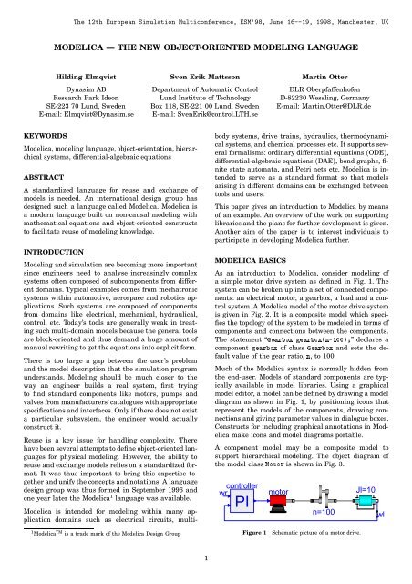
As an introduction to <strong>Modelica</strong>, consider modeling of<br />
a simple motor drive system as defined in Fig. 1. <strong>The</strong><br />
system can be broken up into a set of connected components:<br />
an electrical motor, a gearbox, a load and a control<br />
system. A <strong>Modelica</strong> model of the motor drive system<br />
is given in Fig. 2. It is a composite model which specifies<br />
the topology of the system to be modeled in terms of<br />
components and connections between the components.<br />
<strong>The</strong> statement “Gearbox gearbox(n=100);” declares a<br />
component gearbox of class Gearbox and sets the default<br />
value of the gear ratio, n, to 100.<br />
Much of the <strong>Modelica</strong> syntax is normally hidden from<br />
the end-user. Models of standard components are typically<br />
available in model libraries. Using a graphical<br />
model editor, a model can be defined by drawing a model<br />
diagram as shown in Fig. 1, by positioning icons that<br />
represent the models of the components, drawing connections<br />
and giving parameter values in dialogue boxes.<br />
Constructs for including graphical annotations in <strong>Modelica</strong><br />
make icons and model diagrams portable.<br />
A component model may be a composite model to<br />
support hierarchical modeling. <strong>The</strong> object diagram of<br />
the model class Motor is shown in Fig. 3.<br />
controller<br />
wr<br />
PI<br />
motor<br />
n=100<br />
Jl=10<br />
wl<br />
1 <strong>Modelica</strong> TM is a trade mark of the <strong>Modelica</strong> Design Group<br />
Figure 1<br />
Schematic picture of a motor drive.<br />
1
model MotorDrive<br />
Motor motor;<br />
PI<br />
controller;<br />
Gearbox gearbox(n=100);<br />
Shaft Jl(J=10);<br />
Tachometer wl;<br />
equation<br />
connect(controller.out, motor.in);<br />
connect(motor.flange , gearbox.a);<br />
connect(gearbox.b , Jl.a);<br />
connect(Jl.b<br />
, wl.a);<br />
connect(wl.w<br />
, controller.in);<br />
end MotorDrive;<br />
Figure 2 A <strong>Modelica</strong> model of the system in Fig. 1.<br />
Variables<br />
Physical modeling deals with specifying relations between<br />
physical quantities. For the drive system, quantities<br />
such as angle and torque are of interest. <strong>The</strong>ir<br />
types are declared in <strong>Modelica</strong> as<br />
type Angle = Real(quantity = "Angle",<br />
unit = "rad",<br />
displayUnit = "deg");<br />
type Torque = Real(quantity = "Torque",<br />
unit = "N.m");<br />
where Real is a predefined type, which has a set of<br />
attributes such as name of quantity, unit of measure,<br />
default display unit for input and output, minimum<br />
value, maximum value and initial value.<br />
Connectors and Connections<br />
Connections specify interactions between components.<br />
A connector should contain all quantities needed to<br />
describe the interaction. Voltage and current are needed<br />
for electrical components. Angle and torque are needed<br />
for drive train elements.<br />
connector Pin<br />
connector Flange<br />
Voltage v; Angle r;<br />
flow Current i; flow Torque t;<br />
end Pin;<br />
end Flange;<br />
A connection, connect(Pin1, Pin2), with Pin1 and<br />
Pin2 of connector class Pin, connects the two pins such<br />
that they form one node. This implies two equations,<br />
namely Pin1.v = Pin2.v and Pin1.i + Pin2.i = 0.<br />
<strong>The</strong> first equation indicates that the voltages on both<br />
branches connected together are the same, and the<br />
Vs<br />
Ra=0.5<br />
La=0.05<br />
emf<br />
Jm=1.0E-3<br />
second corresponds to Kirchhoff’s current law saying<br />
that the current sums to zero at a node. Similar laws<br />
apply to flow rates in a piping network and to forces<br />
and torques in a mechanical system. <strong>The</strong> sum-to-zero<br />
equations are generated when the prefix flow is used<br />
in the connector declarations.<br />
Partial models and inheritance<br />
A very important feature in order to build reusable<br />
descriptions is to define and reuse partial models. A<br />
common property of many electrical components is that<br />
they have two pins. This means that it is useful to define<br />
an interface model class TwoPin, that has two pins, p<br />
and n, and a quantity, v, that defines the voltage drop<br />
across the component.<br />
partial model TwoPin<br />
Pin p, n;<br />
Voltage v;<br />
equation<br />
v = p.v - n.v; p.i + n.i = 0;<br />
end TwoPin;<br />
<strong>The</strong> equations define common relations between quantities<br />
of a simple electrical component. <strong>The</strong> keyword partial<br />
indicates that the model class is incomplete. To be<br />
useful, a constitutive equation must be added. To define<br />
a model for a resistor, start from TwoPin and add a parameter<br />
for the resistance and Ohm’s law to define the<br />
behavior.<br />
model Resistor "Ideal resistor"<br />
extends TwoPin;<br />
parameter Resistance R;<br />
equation<br />
R*p.i = v;<br />
end Resistor;<br />
A string between the name of a class and its body is<br />
treated as a comment attribute. Tools may display this<br />
documentation in special ways. <strong>The</strong> keyword parameter<br />
specifies that the quantity is constant during a<br />
simulation experiment, but can change values between<br />
experiments.<br />
For the mechanical parts, it is also useful to define a<br />
shell model with two flange connectors,<br />
partial model TwoFlange<br />
Flange a, b;<br />
end TwoFlange;<br />
A model of a rotating inertia is given by<br />
model Shaft<br />
extends TwoFlange;<br />
parameter Inertia J = 1;<br />
AngularVelocity w;<br />
equation<br />
a.r = b.r;<br />
der(a.r) = w;<br />
J*der(w) = a.t + b.t;<br />
end Shaft;<br />
Figure 3<br />
A motor model.<br />
where der(w) means the time derivative of w.<br />
2
THE IDEAS BEHIND MODELICA<br />
Among the recent research results in modeling and<br />
simulation the two concepts object-oriented and noncausal<br />
modeling have had a strong impact on the <strong>Modelica</strong><br />
design. A new attempt at introducing interoperability<br />
and openness to the world of modeling and<br />
simulation systems is justified by the combined power<br />
of the two concepts together with proven technology<br />
from existing modeling languages such as ASCEND<br />
[Piela et al. (1991)], Dymola[Elmqvist et al. (1996)],<br />
gPROMS [Barton and Pantelides (1994)], NMF[Sahlin<br />
et al. (1996)], <strong>Object</strong>Math [Fritzson et al. (1995)],<br />
Omola [Mattsson et al. (1993)], SIDOPS+ [Breunese<br />
and Broenink (1997), Smile [Kloas et al. (1995)], U.L.M.<br />
[Jeandel et al. (1996)] and VHDL-AMS [IEEE (1997)].<br />
Non-Causal <strong>Modeling</strong><br />
In <strong>Modelica</strong> it is possible to write balance and other<br />
equations in their natural forms as a system of<br />
differential-algebraic equations (DAE). <strong>Modelica</strong> has<br />
been carefully designed in such a way that computer<br />
algebra can be utilized to achieve as efficient simulation<br />
code as if the model would be converted to ODE<br />
form manually. For example, define a gearbox model as<br />
model Gearbox "Ideal gearbox without inertia"<br />
extends TwoFlange;<br />
parameter Real n;<br />
equation<br />
a.r = n*b.r;<br />
n*a.t = b.t;<br />
end Gearbox;<br />
without bothering about what are inputs from a computational<br />
point of view and use it as a component model,<br />
when modeling the drive system in Fig. 1.<br />
Note, that this use actually leads to a non-trivial simulation<br />
problem. <strong>The</strong> ideal gearbox is rigidly connected<br />
to a rotating inertia on each side. It means the model<br />
includes two rigidly connected inertias, since there is no<br />
flexibility in the ideal gearbox. <strong>The</strong> angular position as<br />
well as the velocity of the two inertias should be equal.<br />
All of these four differentiated variables cannot be state<br />
variables with their own independent initial values.<br />
A DAE problem, which includes constraints between differentiated<br />
variables is sometimes called a “high index<br />
DAE”.WhenconvertingittoODEform,itisnecessary<br />
to differentiate some equations and the set of state variables<br />
can be selected smaller than the set of differentiated<br />
variables. <strong>The</strong>re is an efficient algorithm by Pantelides<br />
(1988) for the determination of what equations<br />
to differentiate. In the drive example, the position constraint<br />
needs to be differentiated twice to calculate the<br />
reaction torque in the coupling, and it is sufficient to<br />
select the angle and velocity of either inertia as state<br />
variables. <strong>The</strong> constraint leads to a linear system of simultaneous<br />
equations involving angular accelerations<br />
and torques. A symbolic solution will contain a determinant<br />
of the form “J l +J m n 2 ”. <strong>The</strong> tool thus automatically<br />
deduces how inertia is transformed through a gearbox.<br />
ADVANCED MODELING FEATURES<br />
<strong>The</strong> modeling power of <strong>Modelica</strong> is large. <strong>Modeling</strong> of,<br />
for example, multi-body systems and control systems<br />
is done conveniently by utilizing matrix equations. Itis<br />
also possible to have arrays of components and to define<br />
regular connection patterns. Reuse of model library<br />
components is further supported by allowing model<br />
class parameters.<br />
<strong>Modelica</strong> supports hybrid modeling. Realistic physical<br />
models often contain discontinuities, discrete events or<br />
changes of structure. Examples are relays, switches,<br />
friction, impact, sampled data systems etc. Algorithms<br />
and functions are supported in <strong>Modelica</strong> for modeling<br />
parts of a system in procedural programming style.<br />
STANDARD LIBRARIES<br />
In order that <strong>Modelica</strong> is useful for model exchange, it<br />
is important that libraries of the most commonly used<br />
components are available, ready to use, and sharable<br />
between applications. For this reason, an extensive<br />
<strong>Modelica</strong> base library is under development which<br />
will become an intrinsic part of <strong>Modelica</strong>. It includes<br />
mathematical functions (sin, ln, etc.), type definitions<br />
(e.g., Angle, Voltage), interface definitions (e.g., Pin,<br />
Flange) and component libraries for various domains.<br />
Predefined quantity types and connectors are useful for<br />
standardization of the interfaces between components<br />
and achieve model compatibility without having to<br />
resort to explicit coordination of modeling activities.<br />
Component libraries are mainly derived from already<br />
existing model libraries from various object-oriented<br />
modeling systems. <strong>The</strong>y are realized by specialists in<br />
the respective area, taking advantage of the new features<br />
of <strong>Modelica</strong> not available in the original modeling<br />
system. Libraries of the following areas are under development:<br />
input/output blocks, electric and electronic<br />
components (SPICE3 elements), electric power systems,<br />
drive trains and gear boxes, 3D-mechanical systems<br />
(multi-body systems), hydraulic systems, 1D thermofluid<br />
flow (based on the finite volume method), aircraft<br />
flight system dynamics components, bond graphs, finite<br />
state machines and Petri nets.<br />
DIRECTIONS OF FUTURE DEVELOPMENT<br />
<strong>The</strong> <strong>Modelica</strong> design effort started in the continuous<br />
time domain since there is a common mathematical<br />
framework in the form of differential-algebraic equations<br />
(DAE) and there are several existing modeling<br />
languages based on similar ideas. <strong>The</strong>re is also significant<br />
experience of using these languages in various applications.<br />
It thus seemed to be appropriate to collect<br />
all knowledge and experience and design a new unified<br />
modeling language or neutral format for model representation.<br />
<strong>The</strong> short-range goal was to design a modeling<br />
language for differential-algebraic equation systems<br />
with some discrete event features to handle discontinu-<br />
3
ities and sampled systems. <strong>The</strong> design should be extendible<br />
in order that the goal can be expanded to design<br />
a multi-formalism, multi-domain, general-purpose<br />
modeling language.<br />
<strong>The</strong>re is a need to consider extensions of <strong>Modelica</strong> for<br />
handling of partial differential equations, discrete event<br />
models, etc. Some of these areas are discussed below.<br />
Partial Differential Equations<br />
<strong>The</strong> underlying laws of a model of a technical system are<br />
often of the form of partial differential equations (PDE).<br />
<strong>The</strong> DAE form is then an approximation where certain<br />
quantities are considered independent of the spatial coordinates<br />
within a certain object. For certain phenomena<br />
like heat conduction, convection, laminar and turbulent<br />
flows, and vibrations in flexible mechanical structures,<br />
more accurate PDE models might be needed to<br />
capture the detailed behavior.<br />
A PDE model is defined by (1) a partial differential<br />
equation, (2) the domain of validity of the PDE and<br />
(3) boundary conditions for spatial borders and initial<br />
conditions. <strong>The</strong> domain of validity is typically a geometrical<br />
domain in 1–3 dimensions. A variety of geometry<br />
formats are used by different CAD software. To support<br />
exchange it is necessary to have an application independent<br />
format for representing geometry in <strong>Modelica</strong>.<br />
Discrete Event Models<br />
Further model approximations are done when quantities<br />
are considered to be constant over intervals of time,<br />
i.e., when dealing with discrete event models. <strong>Modelica</strong><br />
already have features for handling discrete variables<br />
and describe how they are changed. However, many issues<br />
of standard discrete event packages have not been<br />
considered yet, such as: function library for various random<br />
distributions, queue handling, how to gather statistical<br />
information, processes and their interaction, animation<br />
features, etc. It would be possible to extend<br />
<strong>Modelica</strong> with such features. However, there are also<br />
many different formalisms for discrete event modeling,<br />
such as: process oriented, activity oriented, Petri nets,<br />
Grafcet, DEVS, State charts and VHDL (discrete circuit<br />
modeling). <strong>The</strong>re are also many discrete event programs<br />
available. In certain cases, modeling is done in a standard<br />
programming language like C++ or Java with the<br />
use of a library of standard functions. Probably, <strong>Modelica</strong><br />
should be both extended with basic discrete event<br />
features, as well as having appropriate interfaces defined<br />
for coupling to external discrete event packages.<br />
Simulator Environment<br />
Most issues about simulating a <strong>Modelica</strong> model is<br />
an internal matter for the simulator. However, for<br />
hardware-in-the-loop simulation one typically needs to<br />
specify which fixed step-size algorithm and what stepsize<br />
to use. <strong>The</strong>re is also a need to specify the coupling<br />
to external input and output hardware. To make such<br />
information portable, a notation in <strong>Modelica</strong> is needed.<br />
In cases when a <strong>Modelica</strong> model, for example, needs to<br />
access medium properties from a data base or be simulated<br />
simultaneously with models in other programs<br />
like a discrete event package, a finite element package<br />
or in a network performing distributed interactive simulation<br />
(DIS), certain information needs to be exchanged.<br />
Such specification needs to be portable, i.e., language<br />
notations are needed in <strong>Modelica</strong>. A possibility would<br />
be to use the High Level Architecture, HLA.<br />
<strong>The</strong>re are also cases when the model description needs<br />
to be augmented in order to help the tool achieve<br />
fast enough simulation. An example is to partition the<br />
model and use multi-rate integration, i.e., to integrate<br />
parts of a model with fast dynamics with shorter stepsize.<br />
Another example is the ability to help the tool<br />
partition the model for execution on different processors<br />
in a parallel architecture. For models with changing<br />
topology, there might also be a need to specify which<br />
configurations are useful. A model with 10 switches can<br />
be in 1024 different modes. If the modeler knows that<br />
maybe only 20 modes are actually used, more efficient<br />
code can be generated than would be possible for the<br />
general case of 1024 modes.<br />
Experiment Specification<br />
When using a mathematical model for simulation or<br />
optimization, the model itself is only a part of the<br />
problem specification. Parameter values, initial values,<br />
start time, stop time or stop condition and how to treat<br />
the result of the simulations are also needed. On a more<br />
lower level it may be of interest to specify solvers and<br />
their parameters.<br />
<strong>The</strong> separation of model, integration algorithm and experiment<br />
is common since a long time. However, what<br />
constitute an experiment is not always obvious. Does a<br />
change of a model parameter belong to an experiment<br />
or to a model? Sometimes the environment of the system<br />
under study is described by some input signals connected<br />
to the model. In certain cases, the “environment”<br />
is described as a dynamic model, i.e., the full power of<br />
<strong>Modelica</strong> is needed. Similarly, describing an optimization<br />
criterion typically contain integration that can be<br />
converted to a differential equation. Even hybrid features<br />
might be needed, for example, to define a maximum<br />
of a signal accurately would involve checking for<br />
the sign shift of the derivative of the signal.<br />
Issues like handling of parameter sets, functions defined<br />
by tables, coupling of inputs, how initialization should<br />
be done, definition of an optimization problem, etc.<br />
needs to be portable between different tools. This means<br />
that <strong>Modelica</strong> should be extended in these directions.<br />
User Environment<br />
<strong>Modelica</strong> already has provisions to describe the graphical<br />
layout of icons and connection topology by means of<br />
annotations. So far, only static pictures have been considered.<br />
When using models for operator training, typically<br />
a live process layout is used to show the status of<br />
4
the process by means of updated numeric text, changing<br />
water level of a tank, etc. <strong>The</strong>re is also a need to input<br />
new parameter values in specially designed forms. <strong>The</strong><br />
annotation attributes could be extended to handle this.<br />
Typically, an interactive user interface for modeling<br />
and simulation needs extensive capabilities for general<br />
matrix calculations and control design algorithms. It<br />
should, of course, be possible to use a <strong>Modelica</strong> tools<br />
with close connections to available packages like Matlab,<br />
Xmath, Matematica, etc. However, for many users<br />
it would be beneficial to use the <strong>Modelica</strong> syntax, the<br />
strong typing property and matrix expressions in an interactive<br />
fashion. <strong>Modelica</strong> functions could then be used<br />
both within a model and be called interactively.<br />
Predefined external functions would specify the interfaces<br />
of simulators, optimizers, display tools etc.<br />
<strong>The</strong>se interfaces should define parameters and operations<br />
which could be done. <strong>Modelica</strong> already supports a<br />
powerful function concept. However, it may be useful to<br />
introduce language constructs which supports member<br />
functions in the ordinary object-oriented meaning.<br />
It should be remembered that high quality tools should<br />
have good interactive graphical user interfaces with<br />
menu selection, dialogue boxes, ability to record menu<br />
commands in script form, etc. A typical user who wants<br />
to solve a problem should not need to write or read this<br />
textual representation.<br />
ORGANIZATION OF MODELICA DESIGN<br />
<strong>The</strong> <strong>Modelica</strong> design effort started as an action in the<br />
ESPRIT project "Simulation in Europe Basic Research<br />
Working Group (SiE-WG)" and is since February 1997<br />
the Technical Committee 1 within Eurosim. <strong>The</strong> <strong>Modelica</strong><br />
Design Group has had 11 meetings to work out the<br />
<strong>Modelica</strong> fundamentals. <strong>The</strong> plan is to make the <strong>Modelica</strong><br />
design effort a Technical Chapter within SCS.<br />
<strong>The</strong> <strong>Modelica</strong> Design Group includes simulation<br />
tool builders, users from different application domains,<br />
and computer scientists. <strong>The</strong> present members (May<br />
1998) are Manuel Alfonseca, Universidad Autonoma<br />
de Madrid, Spain, Bernhard Bachmann, ABB Corporate<br />
Research, Baden-Dättwil, Switzerland, Fabrice<br />
Boudaud and Alexandre Jeandel, Gaz de France, Jan<br />
Broenink, University of Twente, <strong>The</strong> Netherlands, Dag<br />
Brück and Hilding Elmqvist (chairman), Dynasim AB,<br />
Lund, Sweden, Thilo Ernst, GMD-FIRST, Berlin, Germany,<br />
Rüdiger Franke, Technical University of Ilmenau,<br />
Germany, Peter Fritzson, Linköping University, Sweden,<br />
Kaj Juslin, VTT, Finland, Matthias Klose, Technical<br />
University of Berlin, Germany, Sven Erik Mattsson,<br />
Lund University, Sweden, Pieter Mosterman and Martin<br />
Otter, DLR Oberpfaffenhofen, Germany, Per Sahlin,<br />
BrisData AB, Stockholm, Sweden, André Schneider and<br />
Peter Schwarz, Fraunhofer Institute for Integrated Circuits,<br />
Dresden, Germany, Hubertus Tummescheit, GMD<br />
FIRST, Berlin, Germany, Hans Vangheluwe, University<br />
of Gent, Belgium.<br />
CONCLUSIONS<br />
<strong>The</strong> <strong>Modelica</strong> effort has been described and an overview<br />
of <strong>Modelica</strong> has been given. Version 1.0 of <strong>Modelica</strong> was<br />
finished in September 1997. <strong>The</strong>re is ongoing work to<br />
develop model libraries and tools. For more information,<br />
including rationale and definition of <strong>Modelica</strong> and<br />
future developments, see www at <strong>Modelica</strong> (1998).<br />
<strong>The</strong> paper has also outlined some areas that needs to<br />
be developed. We invite individuals with expertize to<br />
participate in extending <strong>Modelica</strong>. If you are interested,<br />
please, contact any of the authors.<br />
Acknowledgements<br />
<strong>The</strong> authors would like to thank the other members of<br />
the <strong>Modelica</strong> Design Group for inspiring discussions and<br />
their contributions to the <strong>Modelica</strong> design.<br />
REFERENCES<br />
BARTON, P.andC.PANTELIDES (1994): “<strong>Modeling</strong> of combined<br />
discrete/continuous processes.” AIChE J., 40, pp. 966–979.<br />
BREUNESE, A.P.andJ.F.BROENINK (1997): “<strong>Modeling</strong> mechatronic<br />
systems using the SIDOPS+ language.” In Proceedings<br />
of ICBGM’97, 3rd International Conference on<br />
Bond Graph <strong>Modeling</strong> and Simulation, Simulation Series,<br />
Vol.29, No.1, pp. 301–306. <strong>The</strong> Society for Computer Simulation<br />
International.<br />
ELMQVIST, H., D. BRÜCK, and M. OTTER (1996): Dymola —<br />
User’s Manual. Dynasim AB, Research Park Ideon, Lund,<br />
Sweden.<br />
FRITZSON, P.,L.VIKLUND, D.FRITZSON, and J. HERBER (1995):<br />
“High-level mathematical modeling and programming.”<br />
IEEE Software, 12:3.<br />
IEEE (1997): “Standard VHDL Analog and Mixed-Signal<br />
Extensions.” Technical Report IEEE 1076.1. IEEE.<br />
JEANDEL, A.,F.BOUDAUD, P.RAVIER, and A. BUHSING (1996):<br />
“U.L.M: Un Langage de Modélisation, a modelling language.”<br />
In Proceedings of the CESA’96 IMACS Multiconference.<br />
IMACS, Lille, France.<br />
KLOAS,M.,V.FRIESEN, and M. SIMONS (1995): “Smile — A simulation<br />
environment for energy systems.” In SYDOW, Ed.,<br />
Proceedings of the 5th International IMACS-Symposium<br />
on Systems Analysis and Simulation (SAS’95), vol. 18–19<br />
of Systems Analysis Modelling Simulation, pp. 503–506.<br />
Gordon and Breach Publishers.<br />
MATTSSON, S.E.,M.ANDERSSON, and K. J. ÅSTRÖM (1993):<br />
“<strong>Object</strong>-oriented modelling and simulation.” In LINKENS,<br />
Ed., CAD for Control Systems, chapter 2, pp. 31–69.<br />
Marcel Dekker Inc, <strong>New</strong> York.<br />
MODELICA (1998): A unified object-oriented language<br />
for physical systems modeling. <strong>Modelica</strong> homepage:<br />
http://www.Dynasim.se/<strong>Modelica</strong>/.<br />
PANTELIDES, C. (1988): “<strong>The</strong> consistent initialization of<br />
differential-algebraic systems.” SIAM Journal of Scientific<br />
and Statistical Computing, 9, pp. 213–231.<br />
PIELA, P., T. EPPERLY, K.WESTERBERG, and A. WESTERBERG<br />
(1991): “ASCEND: An object-oriented computer environment<br />
for modeling and analysis: the modeling language.”<br />
Computers and Chemical Engineering, 15:1, pp. 53–72.<br />
SAHLIN, P.,A.BRING, and E.F.SOWELL (1996): “<strong>The</strong> Neutral<br />
Model Format for building simulation, Version 3.02.”<br />
Technical Report. Department of Building Sciences, <strong>The</strong><br />
Royal Institute of Technology, Stockholm, Sweden.<br />
5