instabus Technical Manual Event-Schedule-Logic Controller, N350 5WG1 350-1AB01
instabus Technical Manual Event-Schedule-Logic Controller, N350 5WG1 350-1AB01
instabus Technical Manual Event-Schedule-Logic Controller, N350 5WG1 350-1AB01

Create successful ePaper yourself
Turn your PDF publications into a flip-book with our unique Google optimized e-Paper software.
USA<br />
<strong>instabus</strong> ® <strong>Technical</strong> <strong>Manual</strong><br />
<strong>Event</strong>-<strong>Schedule</strong>-<strong>Logic</strong><br />
<strong>Controller</strong>, <strong>N<strong>350</strong></strong><br />
<strong>5WG1</strong> <strong>350</strong>-<strong>1AB01</strong><br />
April 2002 / Page 1<br />
Product and Applications Description<br />
The <strong>Event</strong>-<strong>Schedule</strong>-<strong>Logic</strong> <strong>Controller</strong> <strong>N<strong>350</strong></strong> is a DIN rail<br />
mounted device.<br />
In a compact unit the module offers<br />
– <strong>Event</strong> programs,<br />
– <strong>Schedule</strong> programs (weekly scheduler) and<br />
– <strong>Logic</strong> functions<br />
for binary input and output signals.<br />
Up to ten event programs are available. For each event<br />
program up to ten event actions may be activated. An<br />
event program is triggered via an associated event<br />
object. The event trigger type may be chosen from this<br />
list:<br />
– Reception of any telegram (0 or 1)<br />
– Reception of 1<br />
– Reception of 0<br />
– Change from 0 to 1<br />
– Change from 1 to 0<br />
The value sent (0 or 1) can be defined per event action.<br />
The delay of an event action with respect to the time of<br />
the event trigger may also be defined.<br />
The weekly scheduler provides a total of 100 schedules<br />
for 20 time controlled channels. Each schedule switches<br />
a time object on the minute at a pre-defined time on one<br />
or several days of the week.<br />
The schedules are executed based on a controllerinternal<br />
clock which must be synchronized at least once<br />
a day with a master time source. The 4-channel time<br />
switch REG 372 (order number: <strong>5WG1</strong> 372-3EY01), the<br />
4-channel time switch with DCF77 REG 372/02 (order<br />
number: <strong>5WG1</strong> 372-3EY02), the ISDN gateway N147<br />
(order number: <strong>5WG1</strong> 147-<strong>1AB01</strong>), or the IP Interface<br />
AP146 (order number: <strong>5WG1</strong> 146-3AB01) are available<br />
as master time clock or time source.<br />
Ten logic gates, each with up to six inputs and one<br />
output, are available. Each gate’s logic may be selected<br />
from this list: AND, OR, NAND, NOR. Individual logic<br />
gate inputs may be inverted. A send condition „send on<br />
each reception“ or „only on change at output“ can be<br />
configured. A send filter then determines whether any<br />
output value or only 0 or only 1 is sent.<br />
With the ETS (EIB Tool Software) the application<br />
program is selected, its parameters and addresses are<br />
assigned appropriately, and downloaded to the <strong>Event</strong>-<br />
<strong>Schedule</strong>-<strong>Logic</strong> <strong>Controller</strong> N <strong>350</strong>.<br />
Application Programs<br />
01 07 <strong>Event</strong>-<strong>Schedule</strong>-<strong>Logic</strong> 801701<br />
with the functions:<br />
• <strong>Event</strong> Control<br />
• <strong>Schedule</strong> Control (Weekly <strong>Schedule</strong>r)<br />
• <strong>Logic</strong><br />
Application Examples<br />
• Indoor and outdoor lighting control applications<br />
• Lighting control dependent on outdoor light level and<br />
weekly schedule (opening hours)<br />
• Lighting control scenes with dimming in conjunction<br />
with a scene controller<br />
• Timer based lighting control<br />
• Control of shutters, blinds, and shades<br />
• Individual schedules for automated comfort<br />
(heating, lighting, shading...)<br />
• Programming for different life styles and user profiles<br />
(scene control)<br />
• Irrigation control / water storage control<br />
• Activate Garage Door Control / Gate Control<br />
<strong>Technical</strong> Specifications<br />
Power Supply<br />
via bus line<br />
Behavior on bus voltage restoration<br />
After an initialization time of approximately 2 seconds<br />
and a configurable startup delay on restart the N <strong>350</strong> is<br />
operational again.<br />
On restart all event trigger inputs are set to 0. The<br />
controller fetches the current values from the bus. If an<br />
event trigger input is set to 1 during restart and the<br />
event trigger is set to change from 0 to 1 then the event<br />
program is triggered and executed.<br />
On restart all logic gate inputs are set to 0. The<br />
controller fetches the current input values from the bus.<br />
The logic gate sends the result of the logic function to<br />
the bus.<br />
On restart the device gets the time from a master clock.<br />
Until the synchronized time is available all schedule<br />
functions are blocked.<br />
Control elements<br />
1 learning button:<br />
for switching between normal operating mode and<br />
addressing mode<br />
Display elements<br />
1 red LED:<br />
for monitoring nus voltage and displaying mode<br />
selected with learning button<br />
Connections<br />
bus line: pressure contacts on data rail<br />
Physical specifiactions<br />
• polymer casing<br />
• dimensions: DIN rail mounted device<br />
width: 1 SU (1 SU = 18 mm)<br />
• weight: approx. 100 g (4oz)<br />
• installation: rapid mounting on DIN EN 50022-35 x<br />
7,5 rail<br />
Electromagnetic compatibility<br />
complies with Part 15 of the FCC rules pursuant to the<br />
limits for a Class A digital device<br />
Environmental specifications<br />
• ambient temperature operating: - 5 ... + 45° C<br />
(23...113°F)<br />
• maximum ambient temperature range: - 25 ... + 70° C<br />
(-13...158°F)<br />
• relative humidity (non-condensing): 5 % to 93 %<br />
Listings and Certifications<br />
UL listed<br />
UL 916, Energie Management Equipment Accessory<br />
CSA certified<br />
(pending)<br />
CE marked<br />
Complies with EMC regulations (residential and nonresidential<br />
buildings), and low voltage regulations<br />
EIB certified<br />
P.T.O.
USA<br />
<strong>instabus</strong> ® <strong>Technical</strong> <strong>Manual</strong><br />
<strong>Event</strong>-<strong>Schedule</strong>-<strong>Logic</strong><br />
<strong>Controller</strong>, <strong>N<strong>350</strong></strong><br />
<strong>5WG1</strong> <strong>350</strong>-<strong>1AB01</strong><br />
April 2002 / Page 2<br />
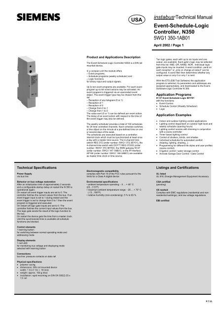
Location and Function of the Display<br />
and Control Elements<br />
A1<br />
A2<br />
A3<br />
A4<br />
WARNING<br />
Disconnect and lock off power before installing or working on the device.<br />
Free DIN rail areas with sticked-in data rails must be covered with covers,<br />
order no. <strong>5WG1</strong> 192-8AA01.<br />
The device must not be opened.<br />
A faulty device should be returned to the local Siemens sales office or distributor.<br />
The device must be mounted and commissioned by a factory trained person.<br />
The prevailing safety rules must be observed!<br />
Mount in dry locations only!<br />
A1<br />
A2<br />
A3<br />
A4<br />
Figure 1: Location of display and operator elements<br />
LED for indicationg normal operating mode (LED<br />
off) and addressing mode (LED on); upon<br />
receiving the physical address the device<br />
automatically returns to operating mode<br />
Learning button for switching between normal<br />
mode and addressing mode<br />
Type plate<br />
Label for noting the physical address<br />
B1<br />
B2<br />
C1<br />
C2<br />
C3<br />
Installation Instructions<br />
The device may be used for permanent interior<br />
installations in dry locations within distribution boards.<br />
Mounting<br />
General description<br />
The N-system DIN rail device (1 SU) can be installed in<br />
N-system distribution boards and any other location or<br />
enclosure with DIN EN 50022-35 x 7,5 rails. Before<br />
mounting the device onto a DIN rail a data rail has to be<br />
glued into it.<br />
The connection to the bus line is established by clicking<br />
the device onto the DIN rail with glued-in data rail. Take<br />
care that the type plates of all devices on a DIN rail can<br />
be read in the same direction guarenteeing the devices<br />
are polarized correctly.<br />
Mounting the device on a DIN rail<br />
Slide the device (B1) onto the DIN rail (B2) and<br />
swivel the device (B1) back onto the DIN rail<br />
until the slide clicks into place audibly.<br />
Dismounting the device from the DIN rail<br />
Press down the slide (C3) with a screw driver and<br />
secure the slide in place by gently pressing it down and<br />
swivel the device (C1) from the DIN rail (C2) to the<br />
front.<br />
Wiring<br />
Wiring is not required.<br />
251503.41.45“c“