simplifying certification of discontinuous composite ... - Hexcel.com
simplifying certification of discontinuous composite ... - Hexcel.com
simplifying certification of discontinuous composite ... - Hexcel.com

Create successful ePaper yourself
Turn your PDF publications into a flip-book with our unique Google optimized e-Paper software.
SIMPLIFYING CERTIFICATION OF DISCONTINUOUS<br />
COMPOSITE MATERIAL FORMS FOR PRIMARY AIRCRAFT<br />
STRUCTURES<br />
Mark Tuttle 1 , Tory Shifman 1 , Bruno Boursier 2<br />
1 Dept. Mechanical Engineering, Box 352600, University <strong>of</strong> Washington, Seattle, WA 98195<br />
2<br />
<strong>Hexcel</strong> Corp., 11711 Dublin Blvd, Dublin, CA 94568<br />
ABSTRACT<br />
Discontinuous Fiber Composite (DFC) parts produced using <strong>com</strong>pression molding are being<br />
implemented in <strong>com</strong>plex structural geometries in new generation <strong>com</strong>mercial aircraft. However,<br />
structural analysis <strong>of</strong> DFC parts is a challenge since DFC materials do not behave like traditional<br />
<strong><strong>com</strong>posite</strong>s nor like isotropic materials. This paper presents some initial results related to the<br />
behavior <strong>of</strong> HexMC ® , a proprietary DFC system produced by the <strong>Hexcel</strong> Corporation. Flat<br />
HexMC test panels were produced using <strong>com</strong>pression molding and used to study the effects <strong>of</strong><br />
material flow on material behavior. The results <strong>of</strong> optical microscopy inspections and tensile<br />
testing are described and discussed.<br />
1. INTRODUCTION<br />
Discontinuous Fiber Composite (DFC) <strong>com</strong>ponents are now being used in <strong>com</strong>mercial airplanes.<br />
The increasing use <strong>of</strong> DFC materials is driven by the fact that (relative to continuous fiber<br />
<strong><strong>com</strong>posite</strong>s) these materials allow <strong>com</strong>pression molding <strong>of</strong> <strong>com</strong>plex parts at relatively low cost.<br />
In addition, DFCs provide high delamination resistance, near quasi-isotropic in-plane stiffness,<br />
high out-<strong>of</strong>-plane strength and stiffness, and low notch sensitivity.<br />
Structural analysis <strong>of</strong> DFC parts is a challenge, since DFC materials do not behave like<br />
traditional <strong><strong>com</strong>posite</strong>s nor like isotropic materials. Further, there are no standards for generating<br />
material allowables, design, or analysis methods. As a result, <strong>certification</strong> <strong>of</strong> DFC parts is<br />
currently achieved by testing a large number <strong>of</strong> parts (i.e. “Point Design”). This is a time<br />
consuming and costly process for the parts manufacturer, the aircraft manufacturer, and the FAA,<br />
and may lead to over-conservative part designs. In order to transition to a more desirable<br />
<strong>certification</strong> process based on analysis supported by test evidence, fundamental material behavior<br />
must be understood, and material allowables and related analysis methods must be developed to<br />
reliably predict the performance <strong>of</strong> structural details.<br />
A multi-year study with an ultimate goal <strong>of</strong> <strong>simplifying</strong> <strong>certification</strong> <strong>of</strong> DFC parts has been<br />
undertaken by members <strong>of</strong> AMTAS (Advanced Materials for Transport Aircraft Structures),<br />
which is one <strong>of</strong> two university groups that together form the Joint Advanced Materials &<br />
Structures (JAMS) Center <strong>of</strong> Excellence. JAMS is supported by the FAA and several industrial<br />
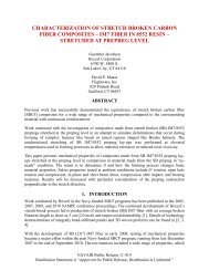
partners [1]. The present study is focused on HexMC ® , a DFC produced by the <strong>Hexcel</strong><br />
Corporation. HexMC consists <strong>of</strong> randomly-distributed carbon-epoxy ‘chips’, which are<br />
themselves produced from unidirectional AS4/8552 pre-preg (see Figure 1). The chips have<br />
nominal in-plane dimensions <strong>of</strong> 8 mm x 50 mm (0.3 x 2 in). Industrial grade HexMC is
Figure 1: Sample <strong>of</strong> HexMC random chipped fiber distribution<br />
<strong>com</strong>mercially available in pre-preg preg form, whereas proprietary aerospace grade HexMC is<br />
provided exclusively by <strong>Hexcel</strong> in the form <strong>of</strong> manufactured and finished parts [2].<br />
The multi-year AMTAS study involves tests and analyses at both the coupon level and at the<br />
<strong>com</strong>ponent level. At the coupon level, <strong>Hexcel</strong> is developing an allowables database for aerospace<br />
grade HexMC in-house, which will be made available to AMTAS participants involved in the<br />
study when <strong>com</strong>pleted. This effort involves performing literally hundreds <strong>of</strong> coupon tests,<br />
including unnotched, open-hole, and filled-hole tensile and <strong>com</strong>pressive tests, bearing and<br />
bearing-by-pass tests using mechanically-fastened joints with varying hole diameter/specimen<br />
width ratios, and buckling/crippling tests, to name but a few. Coupon-level tests intended to<br />
supplement the <strong>Hexcel</strong> allowables testing program are also being conducted at the University <strong>of</strong><br />
Washington (UW). Some <strong>of</strong> these<br />
will be described in this paper.<br />
At the <strong>com</strong>ponent level, an aircraft <strong>com</strong>ponent called an intercostal has been selected for<br />
consideration during the AMTAS study. The intercostal is manufactured by <strong>Hexcel</strong> and is used<br />
by Boeing to provide additional load carrying capability between selected circumferential frames<br />
<strong>of</strong> a transport aircraft fuselage. Various tests <strong>of</strong> intercostals will be performed, and based on both<br />
theses tests and the allowables database semi-empirical empirical analysis methods will be developed to<br />
match the experimental results.<br />
Tests and analyses <strong>of</strong> the intercostal <strong>com</strong>ponents will not be further discussed herein. Rather, the<br />
present paper is devoted to some <strong>of</strong> the coupon-level tests performed at the UW. Specifically,<br />
tests <strong>of</strong> specialized test panels, called ‘high-flow’ panels, will be described. As will be seen,<br />
these panels are produced using non-standard manufacturing processes intended to exaggerate<br />
the impact(s) <strong>of</strong> material flow on fiber/chip structure and tensile properties. The AMTAS team<br />
plans to present additional papers describing the intercostal tests and analyses during future<br />
SAMPE conferences.
2. HIGH-FLOW TEST PANELS<br />
Special ‘high-flow’ test panels were produced to evaluate the effects <strong>of</strong> material flow on fiber<br />
orientation, through-thickness fiber/chip structure, and various mechanical properties. The<br />
panels were produced as summarized in Figure 2. A stack <strong>of</strong> HexMC pre-preg was placed in the<br />
center <strong>of</strong> a simple rectangular mold cavity (Figure 2a). The pre-preg stack had an initial width <strong>of</strong><br />
152 mm (6 in) and length <strong>of</strong> 330 mm (13 in). Application <strong>of</strong> heat and pressure caused the prepreg<br />
to flow throughout the rectangular cavity (Figure 2b), and the panel was removed from the<br />
mold following cure (Figure 2c). Final in-plane plate dimensions were 330 mm x 457 mm (13 in<br />
x 18 in). Hence, material flow resulted in a X3 increase in width. Plates with three different<br />
target thicknesses were produced: 2.3 mm, 3.6 mm, and 5.8 mm (0.09 in, 0.140 in, and 0.230 in).<br />
Plate thickness was increased by increasing the number <strong>of</strong> HexMC plies in the initial ply stack.<br />
The center region <strong>of</strong> the panels experienced relatively low levels <strong>of</strong> chip flow during the molding<br />
process, whereas the left and right regions <strong>of</strong> the panel experienced very high flow levels. The<br />
effects <strong>of</strong> material flow could therefore be explored by studying specimens machined from<br />
different regions <strong>of</strong> the panels.<br />
Tensile specimens were machined from these panels as shown in Figure 3. A numbering system<br />
was adopted that reflected symmetrical specimen locations with respect to the panel centerline.<br />
Specimen width and length was 38 mm (1.5 in) and 330 mm (13 in), respectively.<br />
2.1 Optical Microscopy<br />
High resolution optical micrographs were obtained at several points within the panels. Results<br />
obtained using specimens machined from a 3.6 mm thick panel will be used to illustrate typical<br />
results. Micrographs obtained from specimen 1R, near the center <strong>of</strong> the panel, are shown in<br />
Figure 4. Figures 4a,b show that chips remain approximately planar in low-flow regions. The<br />
absolute value <strong>of</strong> the orientation angle <strong>of</strong> fibers within a given chip can be inferred from the<br />
aspect ratio <strong>of</strong> the polished fiber ends (Fig 4c) and is given by:<br />
y <br />
cos<br />
<br />
[1]<br />
x <br />
By convention the angles returned by Eq 1 were interpreted to be within the first quadrant, i.e.,<br />
0 90 .<br />
In contrast, a micrograph obtained from specimen 6R, near the edge <strong>of</strong> the panel in the high-flow<br />
region, is shown in Figure 5. It is apparent that substantial fiber and chip distortions can occur in<br />
high-flow regions, particularly near the edge <strong>of</strong> the mould. In these areas the chip structure is no<br />
longer even approximately planar.<br />
Having used Eq 1 to determine the fiber orientation <strong>of</strong> individual chips through the thickness <strong>of</strong><br />
the panel, the weighted average fiber orientation can be calculated as:<br />
avg<br />
i<br />
n<br />
<br />
iti<br />
1 [2]<br />
t<br />
tot
(a) HexMC prepreg stack placed in mold cavity<br />
(b) Heat and pressure applied;<br />
material flows to fill mold cavity<br />
(c) Finished test panel<br />
Figure 2: Producing a high-flow test panel<br />
Figure 3: Tensile specimens machined from a high-flow test panel
(a) Polished specimen end (x4 magnification)<br />
y<br />
x<br />
(b) Micrograph showing 8 distinct chips<br />
(x100)<br />
(c) Micrograph used to infer fiber orientation<br />
Figure 4: Optical micrographs obtained from specimen 1R, machined from the low-flow region <strong>of</strong> a<br />
3.6mm thick panel<br />
Figure 5: Optical micrograph <strong>of</strong> edge <strong>of</strong> plate region showing nonplanar chip formation, specimen 6R
Figure 6: Locations 1-4, where weighted average fiber angles were measured<br />
Table 1: Weighted average fiber angles and fiber volume fractions for a 3.6 mm thick panel, at<br />
the locations shown in Figure 6<br />
Location<br />
Number <strong>of</strong><br />
chips, n<br />
Weighted<br />
average fiber<br />
angle (degs)<br />
Fiber volume<br />
fraction (%)<br />
1 38 56.6 54.9<br />
2 34 55.7 54.3<br />
3 26 73.3 N/A<br />
4 24 25.3 54.2<br />
Where t i is the thickness <strong>of</strong> an individual chip, n is the number <strong>of</strong> chips through the thickness <strong>of</strong><br />
the panel, and t tot is the total thickness <strong>of</strong> the panel. If fiber orientations were perfectly random,<br />
and the number <strong>of</strong> chips is very large, then the weighted average fiber orientation would<br />
converge to 45˚. Measured weighted average fiber angles were obtained at the locations shown<br />
in Figure 6. These include the relatively low flow region “1”, an intermediate region “2”, a<br />
region near the low flow edge “3”, and a region near the high flow edge “4”. Results are<br />
tabulated in Table 1. As seen in the table the weighted averages differed significantly from<br />
location to location. Reasonably random orientations were measured at the center <strong>of</strong> the plate<br />
and at the intermediate locations (regions 1 and 2, respectively), where the weighted average<br />
fiber orientations were found to be ~55º. A preferential orientation was measured near both the<br />
low and the high flow edges <strong>of</strong> the mold, however (locations 3 and 4). In these regions the fibers
tend to be<strong>com</strong>e aligned parallel to the edge <strong>of</strong> the mold. As will be seen in a later section, fiber<br />
alignment causes a change in tensile modulus near the edge <strong>of</strong> the panel.<br />
2.2 Fiber Volume Fraction<br />
Fiber volume fractions calculated at sites 1, 2, and 4 for the 3.6 mm thick panel have been<br />
included in Table 1. Fiber volume fractions were also determined for the 2.3mm and 5.8 mm<br />
thick panels. Volume fractions were calculated using Method 2 described in the ASTM D-3171<br />
standard [3]. This procedure involved calculations <strong>of</strong> the volume <strong>of</strong> each specimen as well as<br />
weight measurements to determine the <strong><strong>com</strong>posite</strong> density. The volume fractions were then<br />
derived from the <strong><strong>com</strong>posite</strong> density and their constituent densities, i.e. 1.79 g/cc and 1.30 g/cc for<br />
the fiber and matrix densities respectively. Very little variation in fiber volume fraction from one<br />
point to the next was observed. Volume fractions were also independent <strong>of</strong> panel thickness. It<br />
was concluded that material flow during the molding process had no appreciable impact on fiber<br />
volume fraction.<br />
2.3 Tensile Modulus<br />
Each <strong>of</strong> the three target thickness HexMC panels were sectioned as previously shown in Figure 3<br />
and subjected to a monotonically increasing tensile load until failure occurred. Nominal in-plane<br />
specimen dimensions were 38 mm x 330 mm (1.5 in x 13 in). Axial strains were measured using<br />
an extensometer with a relatively large gage length <strong>of</strong> 50 mm (2 in). A relatively large gage<br />
length was used because the elastic modulus <strong>of</strong> HexMC varies substantially from one point to<br />
another [4]. The level <strong>of</strong> variation can be as high as ±19% and is a reflection <strong>of</strong> the local<br />
through-thickness chip structure and orientation. A large gage length was therefore used so as to<br />
provide a nominal measure <strong>of</strong> modulus that does not reflect point-to-point variations.<br />
The modulus measurements obtained for each <strong>of</strong> the three panel thicknesses are tabulated in<br />
Table 2 and plotted in Figure 7. Recall that the initial 152 mm wide ply stack was centered in<br />
the mold prior to <strong>com</strong>pression molding (see Figure 2a). Since each specimen were nominally 38<br />
mm wide, specimens 2L 2R were machined from the regions <strong>of</strong> the mold occupied by the ply<br />
stack prior to <strong>com</strong>pression molding, as indicated in Figure 7. In contrast, specimens 3L 6L and<br />
3R 6R were machined from (initially) empty regions <strong>of</strong> the mold.<br />
The modulus measurements for specimens 3L, 4L and 3R, 4R do not differ substantially from<br />
those measured for the central specimens. However, a significantly higher tensile modulus was<br />
measured for specimens 5L, 6L and 5R, 6R. That is, the modulus increased as the edge <strong>of</strong> the<br />
mold was approached. Recalling that the fiber volume fraction was found to be constant across<br />
the width <strong>of</strong> the panel, the increase in modulus was attributed to the increased levels <strong>of</strong> fiber<br />
alignment near the edge.<br />
Tensile modulus was found to increase with panel thickness. Based on Figure 7 the modulus over<br />
the central regions defined by specimens 4L through 4R (inclusive) were considered to represent<br />
“typical” values for each <strong>of</strong> the three panel thicknesses. The average modulus measured over<br />
this central region (only) for each panel thickness is included in Table 2 and plotted in Figure 8.<br />
The average modulus for the 5.8 mm thick panel (30.9 GPa) was found to be 31% higher than<br />
the modulus measured for the 2.3 mm panel (23.5 GPa). Once again, fiber volume fraction was<br />
constant for all three panel thicknesses, and therefore cannot account for the measured increase.<br />
The source <strong>of</strong> this increase in stiffness with panel thickness has not yet been identified.
Table 2: Tensile Modulus Measurements for High Flow Panels<br />
Panel Thickness<br />
2.3 mm (0.09 in) 3.6 mm (0.14 in) 5.8 mm (0.23 in)<br />
Ave ± Std Dev<br />
All Specimens, GPa (Msi)<br />
26.8 ± 6.23<br />
(3.88 ± 0.903)<br />
31.5 ± 11.7<br />
(4.57 ± 1.69)<br />
39.6 ± 15.0<br />
(5.75 ± 2.18)<br />
Maximum, GPa (Msi) 38.6 (5.59) 57.5 (8.34) 70.4 (10.2)<br />
Minimum, GPa (Msi) 19.4 (2.81) 19.9 (2.89) 27.5 (3.99)<br />
Average ± Std Dev, 23.5 ± 3.19 25.6 ± 2.73 30.9 ± 2.91<br />
Spec 4L 4R, GPa (Msi) (3.40 ± 0.463) (3.71 ± 0.395) (4.48 ± 0.422)<br />
2.3 mm thick 3.6 mm thick 5.8 mm thick<br />
80.000<br />
Tensile Modulus (GPa)<br />
70.000<br />
60.000<br />
50.000<br />
40.000<br />
30.000<br />
20.000<br />
10.000<br />
0.000<br />
Initial Ply Stack<br />
Region<br />
6L 5L 4L 3L 2L 1L 1R 2R 3R 4R 5R 6R<br />
Specimen Number<br />
Figure 7: Tensile modulus measurements across the width <strong>of</strong> the high-flow test panels<br />
Ave Tensile Modulus (GPa)<br />
32.000<br />
30.000<br />
28.000<br />
26.000<br />
24.000<br />
22.000<br />
20.000<br />
0 2 4 6 8<br />
Panel thickness (mm)<br />
Figure 8: Average tensile modulus measured for high-flow specimens 4L through 4R (inclusive)
2.3 mm thick 3.6 mm thick 5.8 mm thick<br />
Tensile Failure Stress (MPa)<br />
250<br />
200<br />
150<br />
100<br />
50<br />
0<br />
Initial Ply<br />
Stack Region<br />
6L 5L 4L 3L 2L 1L 1R 2R 3R 4R 5R 6R<br />
Specimen Number<br />
Figure 9: Tensile failure stress across the width <strong>of</strong> the high-flow test panels<br />
2.3 mm thick 3.6 mm thick 5.8 mm thick<br />
0.9<br />
Tensile Failure Strain (%)<br />
0.8<br />
0.7<br />
0.6<br />
0.5<br />
0.4<br />
0.3<br />
0.2<br />
0.1<br />
0<br />
Initial Ply<br />
Stack Region<br />
6L 5L 4L 3L 2L 1L 1R 2R 3R 4R 5R 6R<br />
Specimen Number<br />
Figure 10: Tensile failure strain across the width <strong>of</strong> the high-flow test panels<br />
2.4 Tensile Strength<br />
Tensile fracture stress and fracture strains are plotted in Figures 9 and 10, respectively. In the<br />
central regions <strong>of</strong> the panel fracture stress and strains seem to increase with panel thickness.<br />
However, this trend seems to be reversed near the left and right edges <strong>of</strong> the panel. This may be<br />
due to fiber alignment near the edges <strong>of</strong> the panel, as previously discussed. However, given the<br />
large scatter in measured strength values, as well the small number <strong>of</strong> tests performed to date, no<br />
statistically valid conclusions can be reached at this time. Additional testing is needed to clarify<br />
these trends.
3. SUMMARY<br />
A multi-year study with an ultimate goal <strong>of</strong> <strong>simplifying</strong> <strong>certification</strong> <strong>of</strong> Discontinuous Fiber<br />
Composite (DFC) parts has been undertaken by members <strong>of</strong> AMTAS (Advanced Materials for<br />
Transport Aircraft Structures), which is one <strong>of</strong> two university groups that together form the Joint<br />
Advanced Materials & Structures (JAMS) Center <strong>of</strong> Excellence. HexMC ® , a DFC system<br />
produced by the <strong>Hexcel</strong> Corporation, is being used as a model material. The multi-year study<br />
will involve tests and analyses at both the coupon level and at the <strong>com</strong>ponent level.<br />
This paper has focused on tensile tests performed using HexMC coupon specimens that had been<br />
machined from special ‘high-flow’ panels. The high-flow panels experienced far higher levels <strong>of</strong><br />
material flow during the <strong>com</strong>pression molding process than normally occurs during production<br />
<strong>of</strong> an DFC actual part. Panels <strong>of</strong> three different thicknesses were produced and tested: 2.3 mm,<br />
3.6 mm, and 5.8 mm (0.09 in, 0.140 in, and 0.230 in).<br />
It was found that high levels <strong>of</strong> material flow had little or no impact on fiber volume fraction.<br />
Fiber/chip orientations were also found to remain nearly random, even in regions <strong>of</strong> the panel<br />
that had experienced substantial levels <strong>of</strong> material flow. Orientation did occur near the<br />
boundaries <strong>of</strong> the mold cavity. In these latter regions the fiber/chips tend to be<strong>com</strong>e aligned with<br />
the boundary, causing an increase in modulus measured parallel to the boundary.<br />
For a given panel thickness the nominal tensile modulus remained more-or-less constant<br />
throughout interior regions <strong>of</strong> the panel, reflecting essentially random fiber/chip orientation.<br />
Tensile modulus increased markedly in regions near the panel boundary, where fiber/chip<br />
alignment occurred. An unexplained observation was that the nominal tensile modulus increased<br />
with panel thicknesses. The nominal stiffness <strong>of</strong> the 5.8 mm thick panel was 31% higher than<br />
the nominal modulus measured <strong>of</strong> the 2.3 mm panel. The source <strong>of</strong> this increase in stiffness with<br />
panel thickness has not yet been identified.<br />
4. REFERENCES<br />
1. For more information about AMTAS-JAMS see http://depts.washington.edu/amtas/<br />
2. Additional details on both industrial and aerospace-grade HexMC are available at<br />
http://www.hexcel.<strong>com</strong>/Products/Matrix+Products/Other+FRM/HexMC/<br />
3. ASTM Standard D3172, 2009, "Standard Test Methods for Constituent Content <strong>of</strong><br />
Composite Materials," ASTM International, West Conshohocken, PA, 2003, DOI:<br />
10.1520/D3171-09, www.astm.org<br />
4. Feraboli, P., Peitso, E., Cleveland, T., and Stickler, P, “Modulus Measurement for Preprebased<br />
Discontinuous Carbon Fiber/Epoxy Systems”, Journal <strong>of</strong> Composite Materials, Vol 43,<br />
No 19, pp 1947-1965 (2009).