Download - Herion Systemtechnik GmbH
Download - Herion Systemtechnik GmbH
Download - Herion Systemtechnik GmbH

Create successful ePaper yourself
Turn your PDF publications into a flip-book with our unique Google optimized e-Paper software.
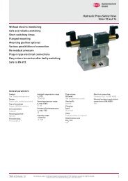
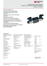
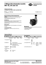
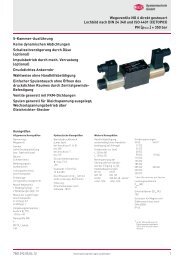
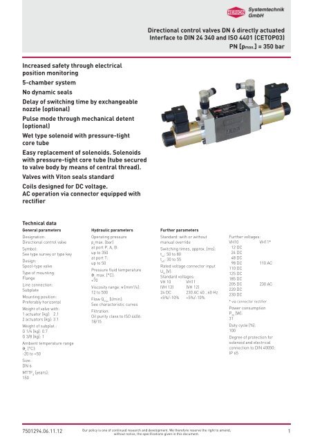
Directional control valves DN 6 directly actuated<br />
Interface to DIN 24 340 and ISO 4401 (CETOP03)<br />
PN [pmax.] = 350 bar<br />
Increased safety through electrical<br />
position monitoring<br />
5-chamber system<br />
No dynamic seals<br />
Delay of switching time by exchangeable<br />
nozzle (optional)<br />
Pulse mode through mechanical detent<br />
(optional)<br />
Wet type solenoid with pressure-tight<br />
core tube<br />
Easy replacement of solenoids. Solenoids<br />
with pressure-tight core tube (tube secured<br />
to valve body by means of central thread).<br />
Valves with Viton seals standard<br />
Coils designed for DC voltage.<br />
AC operation via connector equipped with<br />
rectifier<br />
Technical data<br />
General parameters<br />
Designation:<br />
Directional control valve<br />
Symbol:<br />
See type survey or type key<br />
Design:<br />
Spool-type valve<br />
Type of mounting:<br />
Flange<br />
Line connection:<br />
Subplate<br />
Mounting position:<br />
Preferably horizontal<br />
Weight of valve with:<br />
1 actuator [kg]: 2.1<br />
2 actuators [kg]: 3.1<br />
Weight of subplat.:<br />
G 1/4 [kg]: 0.7<br />
G 3/8 [kg]: 1<br />
Ambient temperature range<br />
J u<br />
[°C]:<br />
-20 to +50<br />
Size:<br />
DN 6<br />
MTTF d<br />
[years]:<br />
150<br />
Hydraulic parameters<br />
Operating pressure<br />
p e<br />
max. [bar]<br />
at port P, A, B:<br />
up to 350<br />
at port T:<br />
up to 50<br />
Pressure fluid temperature<br />
J u<br />
max. [°C]:<br />
+70<br />
Viscosity range: n [mm 2 /s]:<br />
12 to 500<br />
Flow Q max<br />
[l/min]:<br />
See characteristic curves<br />
Filtration:<br />
Oil purity class to ISO 4406:<br />
18/15<br />
Further parameters<br />
Standard: with or without<br />
manual override<br />
Switching times, approx. [ms]:<br />
t on<br />
: 50 to 80<br />
t off<br />
: 30 to 55<br />
Rated voltage connector input<br />
U N<br />
[V]:<br />
Standard voltages:<br />
VH 10 VH11<br />
(VH 13) (VH 12)<br />
24 DC 230 AC 40...60 Hz<br />
+5%/-10% +5%/-10%<br />
Further voltages:<br />
VH10 VH11*<br />
12 DC<br />
24 DC<br />
48 DC<br />
98 DC 110 AC<br />
110 DC<br />
125 DC<br />
185 DC<br />
205 DC 230 AC<br />
220 DC<br />
230 DC<br />
* via connector rectifier<br />
Power consumption<br />
P 20<br />
[W]:<br />
31<br />
Duty cycle [%]:<br />
100<br />
Degree of protection for<br />
solenoid and electrical<br />
connection to DIN 40050:<br />
IP 65<br />
7501294.06.11.12<br />
Our policy is one of continued research and development. We therefore reserve the right to amend,<br />
without notice, the specifications given in this document.<br />
1
Directional control valves DN 6<br />
Electrical parameters (electronic limit switch)<br />
Wiring diagram<br />
Pin assignment limit switch<br />
+ brown<br />
black<br />
- blue<br />
pnp normally open<br />
+ brown<br />
- blue<br />
pnp-antivalent (optional)<br />
antivalent on demand<br />
Electronical limit switch M 12x1:<br />
PNP-Schließer<br />
(oder antivalent auf Anfrage)<br />
Rated operational voltage<br />
U E<br />
[V] DC:<br />
24<br />
Supply voltage<br />
U B<br />
[V] DC:<br />
10 ... 30<br />
Voltage drop<br />
U d<br />
at I e<br />
[V]:<br />
≤1,5<br />
Rated operational current<br />
I e<br />
[mA]:<br />
200<br />
Protection against polarity<br />
reversal:<br />
yes<br />
Short circuit protected/overload<br />
protected:<br />
yes/yes<br />
Load capacitance<br />
[µF]:<br />
≤1,0<br />
Degree of protection per IEC 529:<br />
IP 68 to BWN Pr. 20<br />
(IP 67 connector kompl.)<br />
Connection:<br />
Connector<br />
pressure rated up to<br />
[bar]:<br />
50 an aktiver Fläche<br />
Connector type:<br />
angle, female, 4-pin<br />
Cable gland:<br />
Pg 7, cable ø 4 to 6 mm<br />
Degree of protection:<br />
IP 67<br />
Degree of protection:<br />
yes (2)<br />
- Power on: green<br />
- Function: yellow<br />
2<br />
Our policy is one of continued research and development. We therefore reserve the right to amend,<br />
without notice, the specifications given in this document.<br />
7501294.06.11.12
Directional control valves DN 6<br />
Type key<br />
Directional control valve<br />
S 6 ... ... G ... ... 6 ... V<br />
1 2 3 4 5 6 7<br />
1 Actuation: VH – DC solenoid with manual<br />
override<br />
V – DC solenoid without manual<br />
override<br />
2 Electrical connection: 10 – Connector Pg 11<br />
11 – Connector Pg 11<br />
with rectifier insert on plug<br />
13 – Connector Pg 11 with function<br />
indicator on solenoid<br />
3 Symbol: – Extra symbols see below<br />
– Standard symbols<br />
see page 5 and 6<br />
Subplate<br />
P S 6 G ... ... 2 O O<br />
1 2<br />
1 Line connection: 2 – G 1/4 (internal thread<br />
3 – G 3/8 to DIN ISO 228/1)<br />
2 Code: 024 – G 1/4<br />
001 – G 3/8<br />
1) Only 2-position valves are available with detent.<br />
3) Port T of these 3/2-way valves is to be used as leak oil connection.<br />
Symbol<br />
Symbol<br />
No.<br />
Overlap Symbol Symbol<br />
No.<br />
Overlap Symbol Symbol<br />
No.<br />
Overlap<br />
002 - 038 + 117 +<br />
004 + 039 + 153 -<br />
005 + 082 + 159 +<br />
007 + 086 + 172 +<br />
010 + 087 - 174 +<br />
011 - 088 + 198 +<br />
016 + 090 -<br />
025 + 094 +<br />
031 3) +<br />
033 -<br />
Further symbols on demand<br />
4 Engineering: – For switching position<br />
indicator see next page<br />
6 Additional data: O – Standard design<br />
M 1) – Mechanical detent<br />
7 Sealing material: V – FKM (e.g. Viton<br />
7501294.06.11.12<br />
Our policy is one of continued research and development. We therefore reserve the right to amend,<br />
3<br />
without notice, the specifications given in this document.
Directional control valves DN 6<br />
Code No<br />
for 1 switching position indicator<br />
for 2 switching position indicator<br />
4/2 Directional control valve<br />
210<br />
Solenoid A de-energized<br />
Solenoid A energized<br />
Solenoid at<br />
Side a<br />
Signal to position<br />
switch<br />
Side b<br />
0<br />
1<br />
244<br />
Solenoid A de-energized<br />
Solenoid A energized<br />
Solenoid at<br />
Side a<br />
Signal to position<br />
switch<br />
Side a<br />
0<br />
1<br />
Side b<br />
1<br />
0<br />
217<br />
Solenoid A de-energized<br />
Solenoid A energized<br />
Solenoid at<br />
Side a<br />
Signal to position<br />
switch<br />
Side b<br />
1<br />
0<br />
245<br />
Solenoid A de-energized<br />
Solenoid A energized<br />
Solenoid at<br />
Side a<br />
Signal to position<br />
switch<br />
Side a<br />
1<br />
0<br />
Side b<br />
0<br />
1<br />
Solenoid at<br />
Signal to position<br />
switch<br />
Solenoid at<br />
Signal to position<br />
switch<br />
242<br />
Solenoid B de-energized<br />
Solenoid B energized<br />
Side b<br />
Side a<br />
0<br />
1<br />
246<br />
Solenoid B de-energized<br />
Solenoid B energized<br />
Side b<br />
Side a<br />
1<br />
0<br />
Side b<br />
0<br />
1<br />
Solenoid at<br />
Signal to position<br />
switch<br />
Solenoid at<br />
Signal to position<br />
switch<br />
243<br />
Solenoid B de-energized<br />
Solenoid B energized<br />
Side b<br />
Side a<br />
1<br />
0<br />
247<br />
Solenoid B de-energized<br />
Solenoid B energized<br />
Side b<br />
Side a<br />
0<br />
1<br />
Side b<br />
1<br />
0<br />
4/2 Directional control valve with detent<br />
Solenoid at<br />
Signal to position<br />
switch<br />
222<br />
Solenoid A energized (pulse switching)<br />
Solenoid B energized (pulse switching)<br />
Side a<br />
Side b<br />
Side a<br />
1<br />
0<br />
Solenoid at<br />
Signal to position<br />
switch<br />
Solenoid at<br />
Signal to position<br />
switch<br />
223<br />
Solenoid A energized (pulse switching)<br />
Solenoid B energized (pulse switching)<br />
Side a<br />
Side b<br />
Side a<br />
0<br />
1<br />
238<br />
Solenoid A energized (pulse switching)<br />
Solenoid B energized (pulse switching)<br />
Side a<br />
Side b Side a Side b<br />
1 0<br />
0 1<br />
4/3 Directional control valve<br />
Solenoid at<br />
Signal to position<br />
switch<br />
208<br />
Solenoid A + B de-energized<br />
Solenoid A energized<br />
Solenoid B energized<br />
Side a<br />
Side b<br />
Side b<br />
0<br />
1<br />
1<br />
Solenoid at<br />
Signal to position<br />
switch<br />
Solenoid at<br />
Signal to position<br />
switch<br />
248<br />
Solenoid A + B de-energized<br />
Solenoid A energized<br />
Solenoid B energized<br />
Side a Side b<br />
Side b<br />
1<br />
0<br />
0<br />
216<br />
Solenoid A + B de-energized<br />
Solenoid A energized<br />
Solenoid B energized<br />
Side a<br />
Seite b<br />
Side a<br />
0<br />
1<br />
0<br />
Side b<br />
0<br />
0<br />
1<br />
4<br />
Our policy is one of continued research and development. We therefore reserve the right to amend,<br />
without notice, the specifications given in this document.<br />
7501294.06.11.12
Directional control valves DN 6<br />
Type survey (standard versions)<br />
- Magnet 24VDC (Futher voltages on request)<br />
- With manual override > VH<br />
- Without manual override > V<br />
- Electrical connection, symbol 10 connector 0570275 (Further plugs on demand)<br />
- pnp normally open (andere Nährungsschalter - Ausführungen auf Anfrage)<br />
- Operating pressure: at port P, A and B : 350 bar<br />
- Operating pressure: at port T : 50 bar (210 bar on request)<br />
4/2 Directional control valves (standard versions)<br />
Symbol Symbol-No. Code Type Cat. No.<br />
001 210<br />
S6 VH 10 G 001 210 6OV<br />
5205076.7234.024.00<br />
S6 VH 10 G 001 210 6OV<br />
5205350.7238.024.00<br />
217<br />
001 244<br />
245<br />
003 210<br />
217<br />
003 244<br />
245<br />
020 210<br />
217<br />
020 244<br />
245<br />
S6 VH 10 G 001 217 6OV<br />
S6 VH 10 G 001 217 6OV<br />
S6 VH 10 G 001 244 6OV<br />
S6 VH 10 G 001 244 6OV<br />
S6 VH 10 G 001 245 6OV<br />
S6 VH 10 G 001 245 6OV<br />
S6 VH 10 G 003 210 6OV<br />
S6 VH 10 G 003 210 6OV<br />
S6 VH 10 G 003 217 6OV<br />
S6 VH 10 G 003 217 6OV<br />
S6 VH 10 G 003 244 6OV<br />
S6 VH 10 G 003 244 6OV<br />
S6 VH 10 G 003 245 6OV<br />
S6 VH 10 G 003 245 6OV<br />
S6 VH 10 G 020 210 6OV<br />
S6 VH 10 G 020 210 6OV<br />
S6 VH 10 G 020 217 6OV<br />
S6 VH 10 G 020 217 6OV<br />
S6 VH 10 G 020 244 6OV<br />
S6 VH 10 G 020 244 6OV<br />
S6 VH 10 G 020 245 6OV<br />
S6 VH 10 G 020 245 6OV<br />
on request<br />
on request<br />
on request<br />
on request<br />
on request<br />
on request<br />
on request<br />
on request<br />
on request<br />
5205517.7238 024.00<br />
on request<br />
on request<br />
on request<br />
on request<br />
5205042.7234.024.00<br />
5205257.7238 024.00<br />
5205045.7234 024.00<br />
5205375.7238.024.00<br />
5205662.7234.024.00<br />
5205661.7238.000.00<br />
on request<br />
on request<br />
with mechanical detent<br />
Symbol Symbol-No. Code Type Cat. No.<br />
019 222<br />
223<br />
S6 VH 10 G 013 222 6MV<br />
S6 VH 10 G 013 222 6MV<br />
S6 VH 10 G 013 223 6MV<br />
S6 VH 10 G 013 223 6MV<br />
019 238 S6 VH 10 G 019 238 6MV<br />
S6 VH 10 G 019 238 6MV<br />
5205129.7234.024.00<br />
on request<br />
5205208.7234.024.00<br />
on request<br />
5205659.7234.024.00<br />
5205660.7238.024.00<br />
Further symbols on request.<br />
7501294.06.11.12<br />
Our policy is one of continued research and development. We therefore reserve the right to amend,<br />
5<br />
without notice, the specifications given in this document.
Directional control valves DN 6<br />
4/3 Directional control valves (standard versions)<br />
Symbol Symbol-No. Code Type Cat. No.<br />
008 208<br />
248<br />
S6 VH 10 G 008 208 4OO<br />
S6 VH 10 G 008 208 4OO<br />
S6 VH 10 G 008 248 6OV<br />
S6 VH 10 G 008 248 6OV<br />
008 216 S6 VH 10 G 008 216 6OV<br />
S6 VH 10 G 008 216 6OV<br />
5204785.0000.000.00<br />
5204993.0000.000.00<br />
on request<br />
on request<br />
5205196.7234.024.00<br />
5205467.7238.024.00<br />
009 208<br />
248<br />
S6 VH 10 G 009 208 6OV<br />
S6 VH 10 G 009 208 6OV<br />
S6 VH 10 G 009 248 6OV<br />
S6 VH 10 G 009 248 6OV<br />
009 216 S6 VH 10 G 009 216 6OV<br />
S6 VH 10 G 009 216 6OV<br />
on request<br />
on request<br />
on request<br />
on request<br />
5205365.7234.024.00<br />
on request<br />
013 208<br />
248<br />
S6 VH 10 G 013 208 6OV<br />
S6 VH 10 G 013 208 6OV<br />
S6 VH 10 G 013 248 6OV<br />
S6 VH 10 G 013 248 6OV<br />
013 216 S6 VH 10 G 013 216 6OV<br />
S6 VH 10 G 013 216 6OV<br />
5204786.0000.000.00<br />
on request<br />
on request<br />
on request<br />
5205098.7234.024.00<br />
5205384.7238.024.00<br />
Further symbols on request.<br />
6<br />
Our policy is one of continued research and development. We therefore reserve the right to amend,<br />
without notice, the specifications given in this document.<br />
7501294.06.11.12
Directional control valves DN 6<br />
Characteristic curves<br />
Flow curves Q = f(∆p)<br />
Power limits<br />
ϑ = 50 o C<br />
υ = 28 mm 2 /s<br />
ϑ = 50 o C<br />
υ = 28 mm 2 /s<br />
Flow direction<br />
Symbol<br />
Characteristic curve<br />
Symbol P-A P-B A-T B-T P-T<br />
001 7 7 - - -<br />
003 8 8 3 3 -<br />
008 8 8 6 6 -<br />
009 5 5 9 9 -<br />
013 5 5 4 4 2<br />
019 5 5 1 1 -<br />
020 5 5 1 1 -<br />
001 2<br />
003 4<br />
008 1<br />
009 3<br />
013 5<br />
019 1<br />
020 1<br />
Maximum values determined with solenoid in warmed-up condition<br />
and at an undervoltage of 10%.<br />
Fluid passing in two directions (from P to A and B to T).<br />
If one port is closed, a reduced breaking capacity must be taken into<br />
consideration.<br />
A reduced breaking capacity must also be taken into consideration<br />
for valve types with switching delay (nozzle).<br />
7501294.06.11.12<br />
Our policy is one of continued research and development. We therefore reserve the right to amend,<br />
7<br />
without notice, the specifications given in this document.
Directional control valves DN 6<br />
Ordering<br />
The units are designated by their type number. The composition of<br />
this number can be drawn from the type code. The standard versions<br />
are listed in the type survey. When ordering any of the standard<br />
versions, please state type number as well as catalog number<br />
to preclude possible misinterpretations.<br />
Further valve versions can be composed via combination of types -<br />
order numbers on request.<br />
Flanged valves are provided with O-rings and connector (type 10, 11<br />
and 13). Subplate and mounting screws must be ordered<br />
separately.<br />
Ordering example<br />
4/2-directional control valve<br />
DN 6, 24 V=,<br />
Electrical connection 10,<br />
symbol 020, Schaltstellungsüberwachung<br />
an A- und B-Seite<br />
(code 236), pnp normally open,<br />
subplate G1/4.<br />
Directional control valve:<br />
Type No.:<br />
S 6 VH 10 G 020 236 6 OV<br />
Cat. No.:<br />
5205046.7234.024.00<br />
Subplate:<br />
Type No.:<br />
P S 6 G 2 024 2 O O<br />
Cat. No.:<br />
1065173<br />
Mounting screws:<br />
(4 pcs. required)<br />
Socket-head screw:<br />
(M 5 x 30 DIN 912-10.9)<br />
Cat. No.:<br />
0700387<br />
solenoid at<br />
Signal to position<br />
switch<br />
244<br />
Solenoid A de-energized<br />
Solenoid A energized<br />
Side a<br />
Side a<br />
0<br />
1<br />
Side b<br />
1<br />
0<br />
Design Actuation Mounting Line connection<br />
The design is based upon the<br />
5-chamber system.<br />
A spool of hardened steel slides<br />
in a housing made of highstrength<br />
cast-iron. Therefore the<br />
units are suitable for rough<br />
operating conditions.<br />
The switch contact at the end<br />
positions of the spool can be<br />
used, for example, for acknowledgements<br />
in safety circuits<br />
The directional control valves are<br />
actuated electro-mechanically or<br />
by spring.<br />
The units are bolted on subplates<br />
and sealed by O-rings.<br />
Subplate, interface to<br />
DIN 24340 - A6 and<br />
ISO 4401 - AB - 03 - 4 - A.<br />
8<br />
Our policy is one of continued research and development. We therefore reserve the right to amend,<br />
without notice, the specifications given in this document.<br />
7501294.06.11.12
Directional control valves DN 6<br />
Spare parts drawings<br />
Directional control valve<br />
S 6 VH 10 ...<br />
S 6 VH 11 ...<br />
S 6 VH 13 ... code 210, 217<br />
S 6 VH 10 ...<br />
S 6 VH 11 ...<br />
S 6 VH 13 ... code 244, 245<br />
S 6 VH 10 ...<br />
S 6 VH 11 ...<br />
S 6 VH 13 ... code 242, 243<br />
S 6 VH 10 ...<br />
S 6 VH 11 ...<br />
S 6 VH 13 ... code 246, 247<br />
61<br />
57<br />
61<br />
57<br />
~110<br />
~93 ~3<br />
~110<br />
ca. 93<br />
ca. 3<br />
78 ~73<br />
~178<br />
27 78 73<br />
ca. 208<br />
S 6 VH 10 ... M<br />
S 6 VH 11 ... M<br />
S 6 VH 13 ... M code 222, 223<br />
7501294.06.11.12<br />
Our policy is one of continued research and development. We therefore reserve the right to amend,<br />
9<br />
without notice, the specifications given in this document.
Directional control valves DN 6<br />
S 6 VH 10 ...<br />
S 6 VH 11 ...<br />
S 6 VH 13 ... code 238<br />
61<br />
57<br />
110<br />
ca. 93 ca. 27<br />
72.7 78 22 37 72.7<br />
311.9<br />
S 6 VH 10 ...<br />
S 6 VH 11 ...<br />
S 6 VH 13 ... code 208, 248<br />
S 6 VH 10 ...<br />
S 6 VH 11 ...<br />
S 6 VH 13 ... code 216<br />
10<br />
Our policy is one of continued research and development. We therefore reserve the right to amend,<br />
without notice, the specifications given in this document.<br />
7501294.06.11.12
Directional control valves DN 6<br />
Dimensional drawings<br />
Subplate mit interface according to DIN 24 340-A 6 and ISO 4401-AB-03-4-A<br />
G 1/4<br />
Type: P S 6 G 2 024 2 O O<br />
Reference: 1065173<br />
Aperture for<br />
connection in<br />
control panel<br />
G 3/8<br />
Type: P S 6 G 3 001 2 O O<br />
Reference: 1065183<br />
Aperture for<br />
connection in<br />
control panel<br />
7501294.06.11.12<br />
Our policy is one of continued research and development. We therefore reserve the right to amend,<br />
11<br />
without notice, the specifications given in this document.
Directional control valves DN 6<br />
Electrical spare parts<br />
Electrical connection, Symbol 10<br />
Connector Pg 11<br />
(Operating voltage:<br />
0...300 V DC)<br />
Cat. No.<br />
0570275<br />
Further spares<br />
Cat. No.<br />
O-ring (9.2 x 1.8) 0701728<br />
O-ring (22 x 1,5)<br />
(26.7 x 1.78) on solenoid<br />
Socket-head screw (M5 x 30 DIN 912-10.5) 0700387<br />
Electrical connection, Symbol 11<br />
Connector Pg 11<br />
with rectifier<br />
(Operating voltages:<br />
15...250 V AC or<br />
10...250 V DC)<br />
Cat. No.<br />
0570819<br />
Electrical connection, Symbol 12<br />
Connector Pg 11<br />
with rectifier and indicator<br />
(Operating voltages:<br />
80...130 VAC or<br />
100...130 V DC)<br />
Cat. No.<br />
0588568<br />
Connector Pg 11<br />
with rectifier and indicator<br />
(Operating voltages:<br />
150...250 V AC or<br />
135...250 V DC)<br />
0571502<br />
Electrical connection, Symbol 13<br />
Connector Pg 11<br />
with indicator<br />
(Operating voltages:<br />
24 V DC)<br />
Cat. No.<br />
0570818<br />
Connector Pg 11<br />
with indicator<br />
(Operating voltages:<br />
90...130 V DC)<br />
0570816<br />
Connector Pg 11<br />
with indicator<br />
(Operating voltages:<br />
150...250 V DC)<br />
0570817<br />
Angle plug connector<br />
Proximity switch<br />
Cat. No.<br />
0615517<br />
12<br />
Our policy is one of continued research and development. We therefore reserve the right to amend,<br />
without notice, the specifications given in this document.<br />
7501294.06.11.12
Directional control valves DN 6<br />
HERION <strong>Systemtechnik</strong> <strong>GmbH</strong><br />
Untere Talstraße 65<br />
71263 Weil der Stadt<br />
Tel.: +49 (0) 7033/3018-0<br />
Fax: +49 (0) 7033/3018-10<br />
info@herion-systemtechnik.de<br />
www.herion-systemtechnik.de<br />
A subsidiary of the Norgren and IMI group of companies<br />
Distribution and Service<br />
• in 75 countries through the Norgren service network<br />
HERION <strong>Systemtechnik</strong><br />
Sales Partners<br />
China<br />
ESTUN INDUSTRIAL AUTOMATION CO., LTS<br />
155,Jiangjun Road, Jiangning Economical & Technical<br />
Development Zone, Nanjing, 211100 P.R.C.<br />
Tel.: +86-25-52785915<br />
E-Mail: info@estun.com<br />
www.estun.com<br />
Japan<br />
Riken Optech Corporation<br />
2-6-9, Higashi Ohi, Shinagawa-ku,<br />
Tokyo 140-8533<br />
Tel.: +81 3 34748602<br />
E-Mail: contact@rikenoptech.com<br />
www.rikenoptech.com<br />
Korea<br />
CHUNGWOO CO., LTD.<br />
# 416-4 Dokjeongri<br />
Janganmyun Hwaseongsi<br />
Kyungkido, Korea<br />
Tel.: +82 (0)31 351-5340<br />
E-Mail: blueox2@unitel.co.kr<br />
www.chungwooco.co.kr<br />
Spain<br />
EUROTECH SYSTEMS, S.L.<br />
Av. Can LLuch, 25<br />
08690 SANTA COLOMA DE CERVELLO<br />
Tel: +34 93 634 0101<br />
E-Mail: eurotech@eurotechsys.com<br />
www.eurotechsys.com<br />
South Africa<br />
Ernest Lowe ELCO<br />
Pneumatic & Hydraulic Automation Solutions<br />
6, Skew Road, Boksburg North 1459,<br />
Gauteng, South Africa<br />
Tel.: +27 (11) 898-6600<br />
E-Mail: corporate@elco.co.za<br />
www.elco.co.za<br />
Taiwan<br />
Full Life Trading Co., Ltd.<br />
16F-4, No.2, Jian Ba Rd. Chung Ho City<br />
Taipei County, Taiwan 23562<br />
Tel.: +886-2-82261860<br />
E-Mail: sales-dept@fulllifetrading.com<br />
www.fulllifetrading.com<br />
Turkey<br />
Power Pnomatik Proses A. Ş<br />
Necatibey Cad. No:44/2<br />
Karaköy<br />
Ýstanbul 34420<br />
Tel.: +90 212 2938870<br />
E-Mail: info@powerpnomatik.com<br />
www.powerpnomatik.com<br />
7501294.06.11.12<br />
Our policy is one of continued research and development. We therefore reserve the right to amend,<br />
13<br />
without notice, the specifications given in this document.