A Review of Graphite Foam as Thermal Material
A Review of Graphite Foam as Thermal Material
A Review of Graphite Foam as Thermal Material

You also want an ePaper? Increase the reach of your titles
YUMPU automatically turns print PDFs into web optimized ePapers that Google loves.
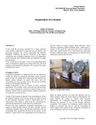
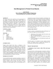
Project Report<br />
200x MVK160 Heat and M<strong>as</strong>s Transport<br />
May 12, 2010, Lund, Sweden<br />
A <strong>Review</strong> <strong>of</strong> <strong>Graphite</strong> <strong>Foam</strong> <strong>as</strong> <strong>Thermal</strong> <strong>Material</strong><br />
Wamei Lin<br />
Dept. <strong>of</strong> Energy Sciences, Faculty <strong>of</strong> Engineering,<br />
Lund University, Box 118, 22100 Lund, Sweden<br />
ABSTRACT<br />
With the incre<strong>as</strong>ing <strong>of</strong> power in equipment, the demand <strong>of</strong><br />
effective cooling methods becomes pressing. The primary<br />
concerns in thermal management applications are high thermal<br />
conductivity, large specific surface area and low weight.<br />
<strong>Graphite</strong> foams which possess predominantly spherical pores<br />
with smaller openings between the cells constitute a novel<br />
highly-conductive porous material for high power equipment<br />
cooling application. These foams can be produced with bulk<br />
thermal conductivities almost equivalent to dense aluminum<br />
alloys with only 20% the weight <strong>of</strong> solid aluminum material.<br />
But in the commercial market, aluminum and copper are still<br />
the preferred material for thermal management. In order to give<br />
an overall view <strong>of</strong> the graphite foam material, this paper will<br />
introduce the structure and the properties <strong>of</strong> the graphite foam.<br />
Meanwhile, the different application for the graphite foam <strong>as</strong> a<br />
thermal material will be outlined and discussed. Some<br />
problems might block the graphite foam heat exchanger<br />
development also will be pointed out. In order to promote the<br />
development <strong>of</strong> graphite foam <strong>as</strong> a thermal material, some<br />
useful conclusion and suggestion will be highlighted in the end.<br />
INTRODUCTION<br />
Nowadays a lot <strong>of</strong> equipment power is incre<strong>as</strong>ed. For instance,<br />
the power <strong>of</strong> computer chips is incre<strong>as</strong>ing, and the power <strong>of</strong><br />
vehicle engines is also incre<strong>as</strong>ing. This incre<strong>as</strong>ing power leads<br />
to the incre<strong>as</strong>ing demand for effective methods <strong>of</strong> cooling.<br />
Currently thermal management h<strong>as</strong> concerned about aluminum<br />
and copper heat exchangers and substrates. This is because <strong>of</strong><br />
the high thermal conductivity (180 W/m.K for aluminum 6061<br />
and 400 W/m.K for copper). But when weight is considered,<br />
the specific thermal conductivity (thermal conductivity divided<br />
by specific gravity) is only 54 and 45 W/m.K respectively.<br />
Thus, where the weight is significant concerned, it is important<br />
to find a light weight, high thermal conductivity and large<br />
specific surface area thermal management material.<br />
An efficient thermal management method is to use a porous<br />
medium to incre<strong>as</strong>e heat transfer by the method <strong>of</strong> incre<strong>as</strong>ing<br />
the fluid-solid contact surface area and promoting fluid mixing.<br />
In this c<strong>as</strong>e, microcellular foam materials like metal or graphite<br />
foams can be considered <strong>as</strong> a cl<strong>as</strong>s novel porous media, in<br />
which there is open cell structure. One example <strong>of</strong> graphite<br />
foam is developed at Oak Ridge National Laboratory in 1997.<br />
Klett et al. [1] found out the thermal conductivity <strong>of</strong> solid<br />
component <strong>of</strong> solid component <strong>of</strong> graphite foam w<strong>as</strong> <strong>as</strong> high <strong>as</strong><br />
1700 W/m.K, which w<strong>as</strong> about four times that <strong>of</strong> copper. The<br />
specific thermal conductivity w<strong>as</strong> more than 150 W/m.K. On<br />
the other hand, the weight <strong>of</strong> graphite foam is only 1/5 that <strong>of</strong><br />
aluminum. The special surface area is between 5000 and 50000<br />
m 2 /m 3 .<br />
Because the graphite foam h<strong>as</strong> very high thermal conductivity,<br />
low weight and large special surface area, it is a very suitable<br />
material that is used in the thermal management. <strong>Graphite</strong> foam<br />
work begins in 1998. It is primarily for power electronic heat<br />
sink. In April 2001, the graphite foam started to be used for<br />
vehicle radiators. A lot <strong>of</strong> studies are carried out to analyze the<br />
graphite foam heat exchangers. But in the current heat<br />
exchanger or heat sink commercial market, aluminum and<br />
copper are still the preferred thermal material. In this c<strong>as</strong>e,<br />
there are still some problems blocking the development <strong>of</strong><br />
graphite foam heat exchangers. Otherwise the graphite foam<br />
heat exchangers can be e<strong>as</strong>ily seen and purch<strong>as</strong>ed in the<br />
market.<br />
In order to promote the development <strong>of</strong> graphite foam <strong>as</strong> a<br />
thermal material, this paper will give a clear overall view or<br />
conception about the graphite foam heat exchanger. First the<br />
structure <strong>of</strong> graphite foam is introduced in Section 2. B<strong>as</strong>ed on<br />
the structure <strong>of</strong> graphite foam, the thermal properties <strong>of</strong><br />
graphite foam will be explained in Section 2 too. After that, the<br />
application <strong>of</strong> graphite foam heat exchanger will be highlighted<br />
in Section 3. In Section 4, some problems blocking the<br />
development <strong>of</strong> graphite foam heat exchangers will be pointed<br />
out. In order to contribute some effort to the development <strong>of</strong><br />
the graphite foam, some useful conclusion and suggestion will<br />
be highlighted in Section 5.<br />
2 STRUCTURE AND THERMAL PROPERTIES OF<br />
GRAPHITE FOAM<br />
Copyright © 2010 by Wamei Lin
2.1 Structures<br />
Carbon foams were first developed in the late 1960s <strong>as</strong> a<br />
reticulated vitreous (gl<strong>as</strong>sy) carbon foam [2]. The initial carbon<br />
foams were made by the pyrolysis <strong>of</strong> a thermosetting polymer<br />
foam to obtain a carbonaceous skeleton or reticulated vitreous<br />
carbon (RVC) foam. Fig. 1 is a photomicrograph <strong>of</strong> a typical<br />
RVC foam.<br />
Fig.2. Photomicrographs <strong>of</strong> the foams produced from<br />
Mitsubishi ARA 24 pitch at different densities A
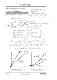
position and vibration <strong>of</strong> atoms in neighboring planes may<br />
impede the vibration <strong>of</strong> atoms in the plane <strong>of</strong> interest. The<br />
crystal perfection controls thermal. In order to achieve high<br />
thermal conductivity in the graphite crystal, the structure must<br />
be comprised <strong>of</strong> aligned, straight grapheme planes, and so on.<br />
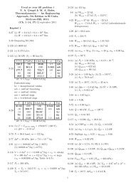
Table 2 Comparison <strong>of</strong> air-cooled heat transfer coefficients<br />
obtained from graphite foam and aluminum. [5]<br />
Table 1 Properties <strong>of</strong> various graphite foams made with the<br />
ORNL method compared to commercially available<br />
Poco<strong>Foam</strong>.[4]<br />
Fig. 4 Plannar structure <strong>of</strong> hexagonal graphite.[4]<br />
On the other hand, Gallego et al. [5] compared the aluminumb<strong>as</strong>ed<br />
heat sink with the graphite foam heat sink. It w<strong>as</strong><br />
demonstrated that the foam-b<strong>as</strong>ed heat sink can be used to<br />
reduce the volume <strong>of</strong> the cooling fluid required or potentially<br />
eliminate the water cooling system altogether, because <strong>of</strong> the<br />
graphite foam high thermal conductivity. Table 2 shows the<br />
cooling performance comparison between graphite foam and<br />
aluminum. In point <strong>of</strong> cooling performance, the graphite foam<br />
is much better than the aluminum. Another useful finding w<strong>as</strong><br />
that the graphite foam heat sinks can respond to transient loads<br />
f<strong>as</strong>ter than the traditional aluminum heat sinks. This response<br />
time may be crucial for power electronics.<br />
2.3 Pressure drop<br />
<strong>Graphite</strong> foam h<strong>as</strong> very high thermal conductivity. But it also<br />
h<strong>as</strong> very high pressure drop. Sraatman et al. [6] conducted a<br />
series <strong>of</strong> experiments to study convection heat transfer<br />
enhancement <strong>of</strong> carbon foams. They found out the pressure<br />
drop across the carbon foam w<strong>as</strong> high due to the large<br />
hydrodynamic loss <strong>as</strong>sociated with the cell windows<br />
connecting the pores. An additional finding w<strong>as</strong> that heat<br />
transfer w<strong>as</strong> not a strong function <strong>of</strong> the foam thickness when<br />
the latter is greater than 3 mm. Tee et al. [7] used a tapered,<br />
anisotropic strut model to predict the overall thermal<br />
conductivity <strong>of</strong> the porous graphite foam. When the size <strong>of</strong><br />
foam pore w<strong>as</strong> incre<strong>as</strong>ed, the pressure drop and the convective<br />
heat transfer coefficient <strong>of</strong> the foam were reduced. The<br />
enhancement <strong>of</strong> convection heat transfer derived from using<br />
graphite foams <strong>as</strong> heat sinks is not only because <strong>of</strong> its open and<br />
inter-connected pores, but also due to its high bulk thermal<br />
conductivity and the extremely large surface are<strong>as</strong>. But the<br />
complex internal structure <strong>of</strong> the foam leads to high flow<br />
resistance, although most pores are open and interconnected.<br />
Thus there is a very high pressure drop through the graphite<br />
foam heat sinks.<br />
2.4 Advantages and disadvantages<br />
B<strong>as</strong>ed on the special structure in graphite foam, the advantages<br />
<strong>of</strong> this material can be summarized:<br />
(1) High thermal conductivities (1700W/m.K);<br />
(2) Low weight, the density is from 0.2 to 0.6 g/cm 3 ;<br />
(3) High special surface area (5000 to 50000m 2 /m 3 ).<br />
On the other hand, there are some disadvantages for the<br />
graphite foam material:<br />
(1) High thermal conductivities only exists in a certain<br />
direction;<br />
Copyright © 2010 by Wamei Lin
(2) Due the complex internal structure <strong>of</strong> the foam, the<br />
pressure drop inside the graphite foam material is very<br />
high.<br />
temperature. However, there seems to have a maximum flow<br />
rate at which no more significant improvement would be<br />
observed.<br />
3 APPLICATION OF GRAPHITE FOAM<br />
Due to the high thermal conductivities, low weight and large<br />
special surface area, the graphite foam is a good material for<br />
heat exchangers or heat sinks. One <strong>of</strong> the important<br />
applications <strong>of</strong> graphite foam heat sink is using in electronic<br />
packages cooling.<br />
3.1 Electronic package cooling<br />
Nowadays, rapid development in the design <strong>of</strong> electronic<br />
packages for modern high-speed computers h<strong>as</strong> led to the<br />
demand for effective methods <strong>of</strong> chip cooling. The use <strong>of</strong><br />
graphite foam h<strong>as</strong> emerged <strong>as</strong> an effective cooling method<br />
because <strong>of</strong> its large internal contact surface are<strong>as</strong> which<br />
enhances convection at the pore level. Another important<br />
re<strong>as</strong>on is that the coolant <strong>of</strong> electronic equipment can be air<br />
instead <strong>of</strong> water, due to the high thermal conductivity. The<br />
removing water can avoid the water leaking short the circuitry<br />
<strong>of</strong> electronic equipment.<br />
Leong et al. [8] carried out experience to investigate heat<br />
transfer in graphite foams <strong>of</strong> four different configurations,<br />
which were used in electronic package cooling. These four<br />
configurations are shown in Fig. 5. After the test, the pressure<br />
drop for these four configurations graphite foam heat sinks is<br />
shown in Fig. 6. For the same inlet flow velocity, block and<br />
baffle foams presented the highest and lowest pressure drop<br />
respectively. Stagger and zigzag structures showed a similar<br />
flow resistance to air flow with pressure drop in the middle<br />
range. Leong et al. [9] used the Finite Volume Method to<br />
simulate these four graphite foam heat sinks. The results<br />
showed that one part <strong>of</strong> flow penetrates through the thin foam<br />
wall and remaining portion <strong>of</strong> air flows through the foam<br />
through the structured empty slots. The velocity distribution in<br />
stagger graphite foam is shown in Fig. 7. It w<strong>as</strong> confirmed that<br />
enhanced convection heat transfer occurred at both the pore<br />
level inside the foam and at the surface <strong>of</strong> the structure foam<br />
wall.<br />
Lu et al. [10] used the graphite foam <strong>as</strong> a wick in a vapor<br />
chamber. With ethanol <strong>as</strong> the coolant, the vapor chamber (25<br />
mm x 25 mm x 6 mm) had been demonstrated at a heat flux <strong>of</strong><br />
80 W/cm 2 . After testing, the results showed that the<br />
performance <strong>of</strong> a vapor chamber using graphite foam is about<br />
twice that <strong>of</strong> one using a copper wick structure. On the other<br />
hand, if the coolant w<strong>as</strong> water, the performance can be<br />
improved more. Williams et al. [11-12] investigated several<br />
different channel insert configuration <strong>as</strong> mini-heat exchangers<br />
using both copper fins and graphite foam. After testing, the<br />
graphite foam w<strong>as</strong> proved to have strong potential <strong>as</strong> a miniheat<br />
exchanger. It w<strong>as</strong> also observed that incre<strong>as</strong>ing the flow<br />
rate in the cooling channel resulted in lower power chip<br />
Fig. 5. Tested graphite foam heat sinks <strong>of</strong> (a) block, (b) stagger,<br />
(c) baffle and (d) zigzag configurations. [8]<br />
Fig. 6. Pressure drop versus inlet flow velocity <strong>of</strong> air flow<br />
through tested configurations. [8]<br />
Fig. 7. Velocity distribution in stagger graphite foams. [9]<br />
Copyright © 2010 by Wamei Lin
It is well known that the usage <strong>of</strong> thermosyphons in the thermal<br />
management <strong>of</strong> electronics is established and the methods for<br />
evaporator enhancement are <strong>of</strong> interest. Gandikota et al. [13]<br />
investigated the cooling performance <strong>of</strong> graphite foam for<br />
evaporator enhancement in thermosyphons and in pool boiling<br />
with FC-72 <strong>as</strong> the operating fluid. The total thermal resistance<br />
for the foam evaporator w<strong>as</strong> shown in Fig. 8. The exhibited<br />
thermal resistance w<strong>as</strong> very low, averaging about 0.024 K/W at<br />
low flux value. The thermal resistance w<strong>as</strong> found to rise with<br />
incre<strong>as</strong>ing heat flux, but still remained advantageously low. On<br />
the other hand, Coursey et al. [14] presented the thermal<br />
performance <strong>of</strong> a graphite foam thermosyphon evaporator. The<br />
usage <strong>of</strong> the graphite foam <strong>as</strong> the evaporator in a thermosyphon<br />
enabled the transfer <strong>of</strong> large amounts <strong>of</strong> energy with<br />
considerable low temperature difference and without the need<br />
for external pumping. The geometry <strong>of</strong> the foam w<strong>as</strong> found to<br />
significantly affect heat transfer in a nonlinear manner by<br />
changing the boiling area and the distance <strong>of</strong> this boiling area.<br />
Incre<strong>as</strong>ing the density <strong>of</strong> the foam w<strong>as</strong> found to linearly affect<br />
heat transfer. After the non-dimensional analysis, it found out<br />
the heat transfer may be reduce due to the small size <strong>of</strong> the<br />
graphite pores. Heat loads <strong>as</strong> high <strong>as</strong> 149W were dissipated<br />
from a 1 cm 2 heated area for 52 degree wall superheat.<br />
the size <strong>of</strong> the front <strong>of</strong> the car can be reduced, the car does not<br />
push <strong>as</strong> much air in its forward motion, allowing it to use fuel<br />
more efficiently. Because a smaller radiator makes a car lighter<br />
and f<strong>as</strong>ter since it allows a more aerodynamic design, it is<br />
interesting for the automotive industry. Kett et al. [15] designed<br />
a radiator (<strong>as</strong> shown in Fig. 9) with the carbon foam. The heat<br />
transfer coefficients incre<strong>as</strong>ed a lot. This leaded to significant<br />
reductions in the number <strong>of</strong> tubes needed for similar heat<br />
transfer. Thus, a typical automotive radiator that is 48 cm x 69<br />
cm might be reduced to 20 cm x 20 cm in cross section with<br />
the same heat removal rate. Such a reduced size will reduce<br />
overall weight, cost, and volume <strong>of</strong> the system. Thereby the<br />
fuel efficiency can be improved.<br />
Fig. 9. <strong>Graphite</strong> foam radiator. [15]<br />
Fig. 8. Heat sink thermal resistance, 10 degree condenser. [13]<br />
3.2 Vehicles cooling system<br />
Another important utilization <strong>of</strong> the graphite foam heat<br />
exchanger is for vehicles cooling. Because the graphite foam is<br />
lightweight and transfer heat rapidly, it might improve the<br />
efficiency <strong>of</strong> transportation vehicles. Meanwhile, some people<br />
believe graphite foam is an enabling technology that will solve<br />
critical heat rejection problems that must be solved before fuel<br />
cell and advanced power electronics technologies are<br />
introduced into automobiles.<br />
The graphite foam could be used to make a smaller, lighter car<br />
radiator. This might by placed away from the front <strong>of</strong> a car to<br />
give an energy saving and less polluting aerodynamic design. If<br />
3.3 Other application<br />
Because <strong>of</strong> the high thermal conductivities in the graphite foam<br />
material, the time used for heat transfer inside the material will<br />
be very short. This is a big advantage for the energy storage<br />
applications. Lafdi et al. [16] investigated and predicted the<br />
thermal performance <strong>of</strong> graphite foams infiltrated with ph<strong>as</strong>e<br />
change materials for space and terrestrial energy storage<br />
systems. Because <strong>of</strong> the high thermal conductivity <strong>of</strong> graphite<br />
foams, the ph<strong>as</strong>e change material and foam system thermal<br />
performance had be improved significantly. Because in the<br />
ph<strong>as</strong>e change material energy storage process the higher<br />
thermal conductivity leads to the shorter time for charging and<br />
discharging time for any ph<strong>as</strong>e change material energy storage.<br />
The short time <strong>of</strong> charging and discharging leads to the better<br />
system performance.<br />
4 PROBLEMS<br />
Even though the graphite foam is an excellent thermal material,<br />
the graphite foam heat exchangers are still rare in the current<br />
commercial market. What problems are blocking the graphite<br />
foam heat exchangers development?<br />
The first problem is faced by the graphite foam heat exchanger<br />
is the high pressure drop. Because <strong>of</strong> the complex internal<br />
structure <strong>of</strong> the foam, the flow resistance inside the graphite<br />
Copyright © 2010 by Wamei Lin
foam is very high. This causes a very high pressure drop inside<br />
the graphite foam heat exchanger. Thus the performance <strong>of</strong> a<br />
graphite foam heat exchanger is controlled more by the surface<br />
area accessed than by the high conductivity <strong>of</strong> the foam. Even<br />
though there is very high specific surface area inside the foam.<br />
Due the high flow resistance, it is difficult for the cooling air to<br />
reach the surface for transferring the heat. In this c<strong>as</strong>e, the<br />
efficient area for heat transfer is reduced a lot. On the other<br />
hand, the high pressure drop requires a very powerful fan to<br />
push the air through the graphite foam heat exchanger. The<br />
powerful fan might be very expensive or very large. In this<br />
c<strong>as</strong>e, it requires a large space for the fan. That may be a<br />
problem when the space is limited. In order to resolve the high<br />
pressure drop problem, it is suggested by Callego et al. [17]<br />
that, the porosity, pore density, ligament structure, and strength<br />
<strong>of</strong> the graphite foam should be optimized simultaneously to<br />
enhance heat transfer with minimal incre<strong>as</strong>e in pressure loses.<br />
The second problem is the mechanical properties. Klett [18]<br />
conceded that the graphite foam w<strong>as</strong> not exceptionally strong.<br />
Its tensile and compressive strength and its other mechanical<br />
properties are not <strong>as</strong> good <strong>as</strong> those <strong>of</strong> aluminum and copper.<br />
H<strong>as</strong>kell et al. [19] tested the thermal properties and the<br />
mechanical properties. It showed that tensile strength <strong>of</strong><br />
graphite foam w<strong>as</strong> much lower than the one <strong>of</strong> aluminum or<br />
copper. The data is shown in Table 4. In the point <strong>of</strong> Klett [18],<br />
when the graphite foam w<strong>as</strong> impregnated with epoxy resin, the<br />
compressive strength can incre<strong>as</strong>e then times. However, by<br />
tweaking the fabrication process to improve the foam's<br />
mechanical properties, the high thermal conductivity might<br />
sacrifice.<br />
Table 4 Comparative thermal and physical properties <strong>of</strong> metals<br />
and foams. [19]<br />
The third problem is the dust blocking. Nowadays most<br />
researches about the graphite foam heat exchangers or heat<br />
sinks focus on the electronic equipment cooling. Little work is<br />
on vehicle radiator application. The main re<strong>as</strong>on for this is the<br />
dust blocking problem. Due to the structure <strong>of</strong> graphite foam, it<br />
is e<strong>as</strong>y to block the open cells inside the foams by dust, if there<br />
is a lot <strong>of</strong> dust in the air. Meanwhile it is difficult to clean the<br />
dust inside the open cells. This will reduce the efficient surface<br />
area for heat transfer. Thus the thermal performance will be<br />
reduced. In the electronic cooling application, the ambient air<br />
normally is clean. Not much dust is inside the air. So the dust<br />
blocking problem is not so serious in the graphite foam heat<br />
exchangers which are used for electronic package cooling.<br />
When the graphite foam heat exchanger is used <strong>as</strong> a radiator to<br />
cool a car engine, the air around the radiator is full <strong>of</strong> dust<br />
(when the car is driven on a road or mountain). In this<br />
situation, the open cells inside the graphite foam heat<br />
exchanger will be blocked by dust e<strong>as</strong>ily. So the blocking<br />
problem is more serious in the radiators than the electronic<br />
cooling heat sinks.<br />
Due to these problems, the development <strong>of</strong> the graphite foam is<br />
very slow and difficult. A lot <strong>of</strong> work h<strong>as</strong> to be done before a<br />
good commercial graphite foam heat exchanger appears in the<br />
market.<br />
CONCLUSIONS AND SUGGESTIONS<br />
The graphite foam h<strong>as</strong> very high thermal conductivity, low<br />
weight and large specific surface area. These properties make<br />
the graphite foam is good for thermal material. The graphite<br />
foam can be used <strong>as</strong> heat sinks to cool the electronic packages.<br />
Meanwhile the graphite foam can be used <strong>as</strong> a radiator to cool<br />
the vehicle engines. Sometimes, the graphite foam can be used<br />
in the energy storage application.<br />
However, due to the complex internal structure <strong>of</strong> graphite<br />
foam, there is very high pressure drop when the air goes<br />
through the graphite foam. This might be required a very<br />
powerful fan. There are some other disadvantages for the<br />
graphite foam. One is the low tensile strength. Another one is<br />
the high thermal conductivity only exists in a certain direction.<br />
All these problems block the development <strong>of</strong> graphite <strong>as</strong><br />
thermal material.<br />
A lot <strong>of</strong> work h<strong>as</strong> to be done on the graphite foam. But the most<br />
important work is to improve the manufacture process, so that<br />
the internal structure <strong>of</strong> the graphite can be changed. After<br />
improving the internal structure, the pressure drop might be<br />
reduced, and the tensile strength may be incre<strong>as</strong>ed.<br />
REFERENCES<br />
[1] Klett, J., Hardy, R., Romine, E., Walls, C., and<br />
Burchell, T., 2000, “High-thermal-conductivity,<br />
Mesoph<strong>as</strong>e-pitch-derived Carbon <strong>Foam</strong>s: Effect <strong>of</strong><br />
Precursor on Structure and Properties”, Carbon 38, pp.<br />
953-973.<br />
[2] Ford, W., 1964, “Method <strong>of</strong> Making Cellular<br />
Refractory <strong>Thermal</strong> Insulating <strong>Material</strong>”, US Patent<br />
3,121,050.<br />
[3] Klett, J. W., 2000, “Process for Making Carbon <strong>Foam</strong>”<br />
US Patent 6033506.<br />
[4] Klett, J. W., Mcmillan, A. D., Gallego, N. C., Walls, C.<br />
A., 2004, “The Role <strong>of</strong> Structure on the <strong>Thermal</strong><br />
Copyright © 2010 by Wamei Lin
[5] Gallego, N. C., and Klett, J. W., 2003, “Carbon <strong>Foam</strong>s<br />
for <strong>Thermal</strong> Management”, Carbon 41, pp. 1461-1466.<br />
[6] Straatman, A. G., Gallego, N. G., Yu, Q., and<br />
Thompson, B. E., 2007, “Characterization <strong>of</strong> Porous<br />
Carbon <strong>Foam</strong> <strong>as</strong> a <strong>Material</strong> for Compact<br />
Recuperators”, Journal <strong>of</strong> Engineering for G<strong>as</strong><br />
Turbines and Power 129, pp. 326-330.<br />
[7] Tee, C. C., Yu, N., and Li, H., 2008, “Modeling the<br />
Overall Heat Conductive and Convective Properties <strong>of</strong><br />
Open-cell <strong>Graphite</strong> <strong>Foam</strong>”, Modelling Simul. Mater.<br />
Sci. Eng. 16, 075006.<br />
[8] Leong, K. C., Jin, L. W., Li, H. Y., and Chai, J. C.,<br />
2008, “Forced Convection Air Cooling in Porous<br />
<strong>Graphite</strong> <strong>Foam</strong> for <strong>Thermal</strong> Management<br />
Application”,<br />
[9] Leong, K. C., Li, H. Y., Jin, L. W., and Chai, J. C.,<br />
“Convective Heat Transfer in <strong>Graphite</strong> <strong>Foam</strong>s with<br />
Complex Structures”, <strong>Thermal</strong> Issues in Emerging<br />
Technologies, ThETA 2, Cairo, Egypt, Dec 17-20 th<br />
2008, pp. 419-428.<br />
[10] Lu, M. H., Mok, L., and Bezama, R. J., 2006, “A<br />
<strong>Graphite</strong> <strong>Foam</strong>s B<strong>as</strong>ed Vapor Chamber for Chip Heat<br />
Spreading”, Journal <strong>of</strong> Electronic Packaging 128, pp.<br />
427-431.<br />
[11] Williams, Z. A., and Roux, J. A., 2006, “<strong>Graphite</strong><br />
<strong>Foam</strong> <strong>Thermal</strong> Management <strong>of</strong> a High Packing<br />
Density Array <strong>of</strong> Power Amplifiers”, Journal <strong>of</strong><br />
Electronic Packaging 128, pp. 456-465.<br />
[12] Williams, Z. A., and Roux, J. A., 2007, “<strong>Thermal</strong><br />
Management <strong>of</strong> a High Packing Density Array <strong>of</strong><br />
Power Amplifiers Using Liquid Cooling”, Journal <strong>of</strong><br />
Electronic Packaging129, pp. 488-495.<br />
[13] Gandikota, V., and Fleischer, A. S., 2009,<br />
“Experimental Investigation <strong>of</strong> the <strong>Thermal</strong><br />
Performance <strong>of</strong> <strong>Graphite</strong> <strong>Foam</strong> for Evaporator<br />
Enhancement in Both Boiling and an FC-72<br />
Thermosyphon”, Heat Transfer Engineering 30(8), pp.<br />
643-648.<br />
[14] Coursey, J. S., Kim, J., and Boudreaux, P. J., 2005,<br />
“Performance <strong>of</strong> <strong>Graphite</strong> <strong>Foam</strong> Evaporator for Use in<br />
<strong>Thermal</strong> Management”, Journal <strong>of</strong> Electronic<br />
Packaging 127, pp. 127-134.<br />
[15] Klett, J., Ott, R., and McMillan, A., 2000, ”Heat<br />
Exchangers for Heavy Vehicles Utilizing High<br />
<strong>Thermal</strong> Conductivity <strong>Graphite</strong> <strong>Foam</strong>s”, SAE<br />
Technical Paper 2000-01-2207.<br />
[16] Lafdi, K., Mesalhy, O., and Elgafy, A., 2008,<br />
“<strong>Graphite</strong> <strong>Foam</strong>s Infiltrated with Ph<strong>as</strong>e Change<br />
<strong>Material</strong>s <strong>as</strong> Alternative <strong>Material</strong>s for Space and<br />
Terrestrial <strong>Thermal</strong> Energy Storage Applications”,<br />
Carbon 46, pp. 159-168.<br />
[17] Galleg, N. C., Shih, A., Stinton, D. P., and Jih, E.,<br />
“<strong>Graphite</strong> <strong>Foam</strong> for Cooling <strong>of</strong> Automotive Power<br />
Electronics”,<br />
http://www.ornl.gov/~webworks/cppr/y2004/pres/120<br />
168.pdf.<br />
[18] http://www.ornl.gov/info/ornlreview/v33_3_00/foam.h<br />
tm.<br />
[19] http://www.electronics-cooling.com/2006/02/thermalresistance-comparison-<strong>of</strong>-graphite-foam-aluminumand-copper-heat-sinks/<br />
Copyright © 2010 by Wamei Lin